2006 INFINITI M35 stop start
[x] Cancel search: stop startPage 1366 of 5621
![INFINITI M35 2006 Factory Service Manual TROUBLE DIAGNOSIS
BRC-55
[VDC/TCS/ABS]
C
D
E
G
H
I
J
K
L
MA
B
BRC
Revision: 2006 January2006 M35/M45
Symptom 3 The Braking Distance Is LongNFS000R6
CAUTION:
The stopping distance on slippery road INFINITI M35 2006 Factory Service Manual TROUBLE DIAGNOSIS
BRC-55
[VDC/TCS/ABS]
C
D
E
G
H
I
J
K
L
MA
B
BRC
Revision: 2006 January2006 M35/M45
Symptom 3 The Braking Distance Is LongNFS000R6
CAUTION:
The stopping distance on slippery road](/manual-img/42/57023/w960_57023-1365.png)
TROUBLE DIAGNOSIS
BRC-55
[VDC/TCS/ABS]
C
D
E
G
H
I
J
K
L
MA
B
BRC
Revision: 2006 January2006 M35/M45
Symptom 3 The Braking Distance Is LongNFS000R6
CAUTION:
The stopping distance on slippery road surfaces might be longer with the ABS operating than when
the ABS is not operating.
1. CHECK FUNCTION
Turn ignition switch OFF and disconnect ABS actuator and electric unit (control unit) connector to deactivate
ABS. In this condition, check stopping distance. After inspection, connect connector.
OK or NG
OK >> GO TO procedure 3 “CHECK WHEEL SENSOR AND SENSOR ROTOR” of symptom 1. Refer to
BRC-53, "
Symptom 1 Excessive ABS Function Operation Frequency" .
NG >> Check brake system.
Symptom 4 ABS Function Does Not OperateNFS000R7
CAUTION:
ABS does not operate when speed is 10 km/h (6 MPH) or lower.
1. CHECK ABS WARNING LAMP DISPLAY
Make sure that the ABS warning lamp turns OFF after ignition switch is turned on or when driving.
OK or NG
OK >> GO TO procedure 3 “CHECK WHEEL SENSOR AND SENSOR ROTOR” of symptom 1. Refer to
BRC-53, "
Symptom 1 Excessive ABS Function Operation Frequency" .
NG >> Perform self-diagnosis. Refer to BRC-23, "
Self-Diagnosis" .
Symptom 5 Pedal Vibration or ABS Operation Sound OccursNFS000R8
CAUTION:
Under the following conditions, ABS is activated and vibration is felt when brake pedal is lightly
depressed (just place a foot on it).However, this is normal.
When shifting gears
When driving on slippery road
During cornering at high speed
When passing over bumps or grooves [at approximately 50 mm (1.97 in) or more]
When pulling away just after starting engine [at approximately 10 km/h (6 MPH) or higher]
1. SYMPTOM CHECK 1
Check if there is pedal vibration or operation sound when the engine is started.
Do symptoms occur?
YES >> GO TO 2.
NO >> Perform self -diagnosis. Refer to BRC-23, "
Self-Diagnosis" .
2. SYMPTOM CHECK 2
Check symptoms when electrical component (headlamps, etc.) switches are operated.
Do symptoms occur?
YES >> Check if there is a radio, antenna, antenna lead wire, or wiring close to the control unit. If there is,
move it farther away.
NO >> GO TO procedure 3 “CHECK WHEEL SENSOR AND SENSOR ROTOR” of symptom 1. Refer to
BRC-53, "
Symptom 1 Excessive ABS Function Operation Frequency" .
Page 1466 of 5621

UNIFIED METER AND A/C AMP
DI-33
C
D
E
F
G
H
I
J
L
MA
B
DI
Revision: 2006 January2006 M35/M45
DATA MONITOR
Operation Procedure
1. Touch “DATA MONITOR” on “SELECT DIAG MODE” screen.
2. Touch either “MAIN SIGNALS” or “SELECTION FROM MENU” on the “DATA MONITOR” screen.
3. When “SELECTION FROM MENU” is selected, touch individual items to be monitored. When “MAIN SIG-
NALS” is selected, main items will be monitored.
4. Touch “START”.
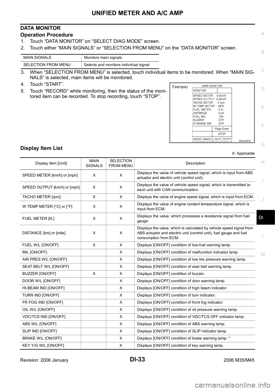
5. Touch “RECORD” while monitoring, then the status of the moni-
tored item can be recorded. To stop recording, touch “STOP”.
Display Item List
X: Applicable MAIN SIGNALS Monitors main signals.
SELECTION FROM MENU Selects and monitors individual signal.
SKIA4957E
Display item [Unit]MAIN
SIGNALSSELECTION
FROM MENUDescription
SPEED METER [km/h] or [mph] X XDisplays the value of vehicle speed signal, which is input from ABS
actuator and electric unit (control unit).
SPEED OUTPUT [km/h] or [mph] X XDisplays the value of vehicle speed signal, which is transmitted to
each unit with CAN communication.
TACHO METER [rpm] X X Displays the value of engine speed signal, which is input from ECM.
W TEMP METER [
C] or [F] X XDisplays the value of engine coolant temperature signal, which is
input from ECM.
FUEL METER [lit.] X XDisplays the value, which processes a resistance signal from fuel
gauge.
DISTANCE [km] or [mile] X XDisplays the value, which is calculated by vehicle speed signal from
ABS actuator and electric unit (control unit), fuel gauge and fuel
consumption from ECM.
FUEL W/L [ON/OFF] X X Displays [ON/OFF] condition of low-fuel warning lamp.
MIL [ON/OFF] X Displays [ON/OFF] condition of malfunction indicator lamp.
AIR PRES W/L [ON/OFF] X Displays [ON/OFF] condition of low tire pressure warning lamp.
SEAT BELT W/L [ON/OFF] X Displays [ON/OFF] condition of seat belt warning lamp.
BUZZER [ON/OFF] X X Displays [ON/OFF] condition of buzzer.
DOOR W/L [ON/OFF] X Displays [ON/OFF] condition of door warning lamp.
HI-BEAM IND [ON/OFF] X Displays [ON/OFF] condition of high beam indicator.
TURN IND [ON/OFF] X Displays [ON/OFF] condition of turn indicator.
FR FOG IND [ON/OFF] X Displays [ON/OFF] condition of front fog indicator.
OIL W/L [ON/OFF] X Displays [ON/OFF] condition of oil pressure warning lamp.
VDC/TCS IND [ON/OFF] X Displays [ON/OFF] condition of VDC/TCS OFF indicator lamp.
ABS W/L [ON/OFF] X Displays [ON/OFF] condition of ABS warning lamp.
SLIP IND [ON/OFF] X Displays [ON/OFF] condition of SLIP indicator lamp.
BRAKE W/L [ON/OFF] X Displays [ON/OFF] condition of brake warning lamp. *
KEY Y/G W/L [ON/OFF] X Displays [ON/OFF] condition of key warning lamp.
Page 1502 of 5621

WARNING CHIME
DI-69
C
D
E
F
G
H
I
J
L
MA
B
DI
Revision: 2006 January2006 M35/M45
CONSULT-II Function (BCM)NKS003V5
CONSULT-II can display each diagnostic item using the diagnostic test modes shown following.
CONSULT-II BASIC OPERATION
CAUTION:
If CONSULT-II is used with no connection of CONSULT-II CONVERTER, malfunctions might be
detected in self-diagnosis depending on control unit which carry out CAN communication.
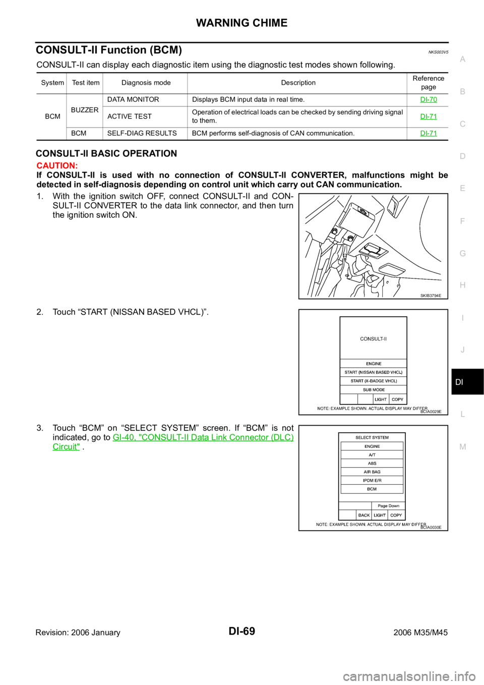
1. With the ignition switch OFF, connect CONSULT-II and CON-
SULT-II CONVERTER to the data link connector, and then turn
the ignition switch ON.
2. Touch “START (NISSAN BASED VHCL)”.
3. Touch “BCM” on “SELECT SYSTEM” screen. If “BCM” is not
indicated, go to GI-40, "
CONSULT-II Data Link Connector (DLC)
Circuit" .
System Test item Diagnosis mode DescriptionReference
page
BCMBUZZERDATA MONITOR Displays BCM input data in real time.DI-70
ACTIVE TESTOperation of electrical loads can be checked by sending driving signal
to them.DI-71
BCM SELF-DIAG RESULTS BCM performs self-diagnosis of CAN communication.DI-71
SKIB3794E
BCIA0029E
BCIA0030E
Page 1518 of 5621

LANE DEPARTURE WARNING SYSTEM
DI-85
C
D
E
F
G
H
I
J
L
MA
B
DI
Revision: 2006 January2006 M35/M45
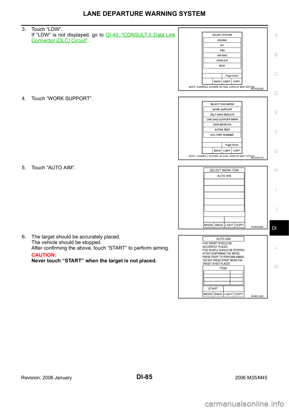
3. Touch “LDW”.
If “LDW” is not displayed, go to GI-40, "
CONSULT-II Data Link
Connector (DLC) Circuit" .
4. Touch “WORK SUPPORT”.
5. Touch “AUTO AIM”.
6. The target should be accurately placed.
The vehicle should be stopped.
After confirming the above, touch “START” to perform aiming.
CAUTION:
Never touch “START” when the target is not placed.
BCIA0030E
BCIA0031E
PKIB4696E
SKIB3146E
Page 1538 of 5621

COMPASS
DI-105
C
D
E
F
G
H
I
J
L
MA
B
DI
Revision: 2006 January2006 M35/M45
COMPASSPFP:24835
System DescriptionNKS003W3
This unit displays earth magnetism and heading direction of vehicle.
DIRECTION DISPLAY
Push “COMP” switch (1) when ignition switch is in “ON” or “START”
position. The direction will be displayed.
Pushing “COMP” switch (1) a second time will turn off the display (2).
NOTE:
Do not install the ski rack, antenna, etc. which are attached to
the vehicle by means of a magnet. They affect the operation of
the compass.
The compass may not indicate the correct compass point in tun-
nels or while driving up or down a steep hill. (The compass
returns to the correct compass point when the vehicle moves to
an area where the geomagnetism is stabilized.)
When cleaning the mirror, use a paper towel or similar material
dampened with glass cleaner. Do not spray glass cleaner directly on the mirror as that may cause the liq-
uid cleaner to enter the mirror housing.
Zone Variation Change ProcedureNKS003W4
The difference between magnetic north and geographical north is known as variance. In some areas, this dif-
ference can sometimes be great enough to cause false compass reading.
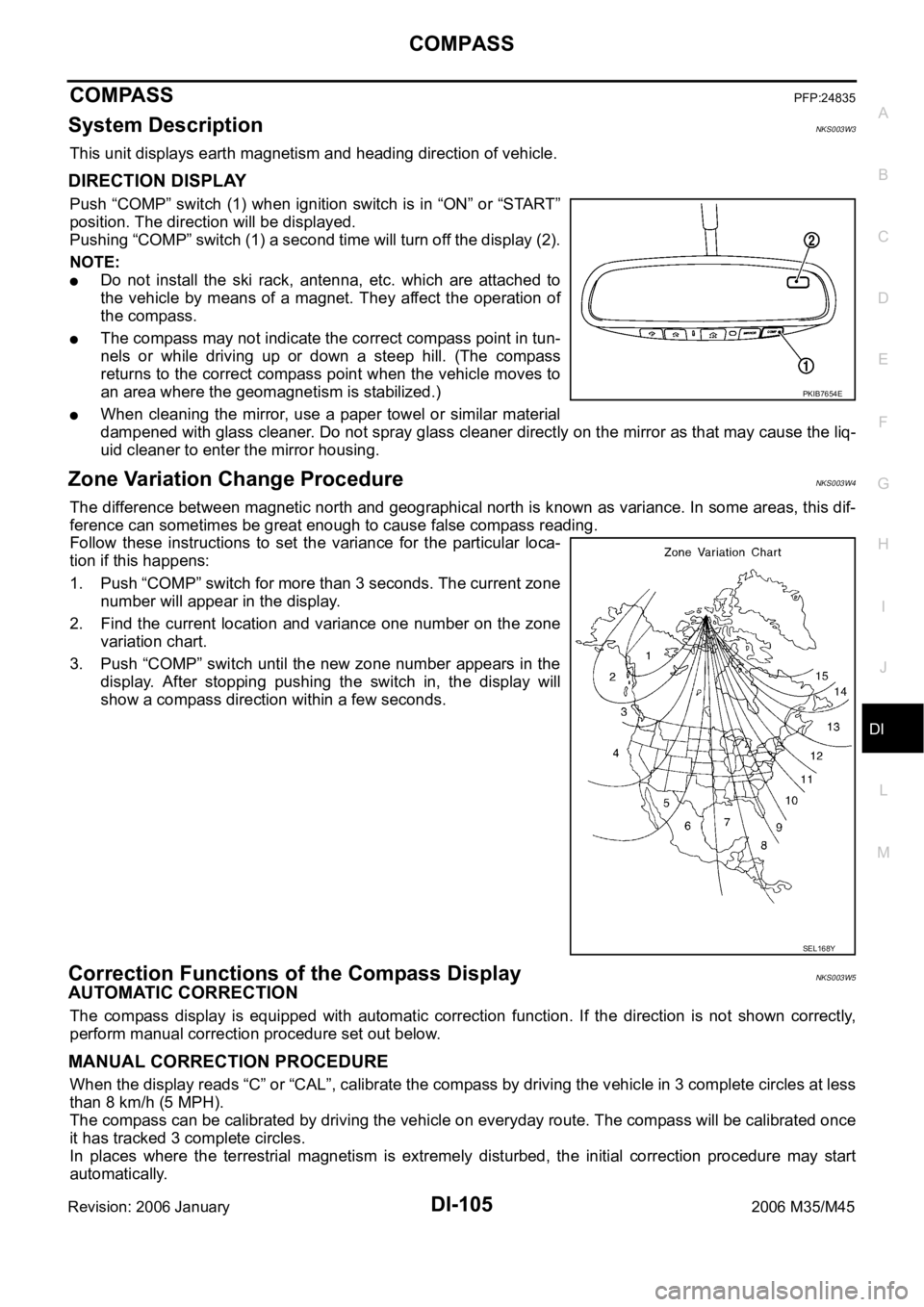
Follow these instructions to set the variance for the particular loca-
tion if this happens:
1. Push “COMP” switch for more than 3 seconds. The current zone
number will appear in the display.
2. Find the current location and variance one number on the zone
variation chart.
3. Push “COMP” switch until the new zone number appears in the
display. After stopping pushing the switch in, the display will
show a compass direction within a few seconds.
Correction Functions of the Compass DisplayNKS003W5
AUTOMATIC CORRECTION
The compass display is equipped with automatic correction function. If the direction is not shown correctly,
perform manual correction procedure set out below.
MANUAL CORRECTION PROCEDURE
When the display reads “C” or “CAL”, calibrate the compass by driving the vehicle in 3 complete circles at less
than 8 km/h (5 MPH).
The compass can be calibrated by driving the vehicle on everyday route. The compass will be calibrated once
it has tracked 3 complete circles.
In places where the terrestrial magnetism is extremely disturbed, the initial correction procedure may start
automatically.
PKIB7654E
SEL168Y
Page 1575 of 5621
![INFINITI M35 2006 Factory Service Manual EC-32
[VQ35DE]
ENGINE CONTROL SYSTEM
Revision: 2006 January2006 M35/M45
MIXTURE RATIO FEEDBACK CONTROL (CLOSED LOOP CONTROL)
The mixture ratio feedback system provides the best air-fuel mixture ratio INFINITI M35 2006 Factory Service Manual EC-32
[VQ35DE]
ENGINE CONTROL SYSTEM
Revision: 2006 January2006 M35/M45
MIXTURE RATIO FEEDBACK CONTROL (CLOSED LOOP CONTROL)
The mixture ratio feedback system provides the best air-fuel mixture ratio](/manual-img/42/57023/w960_57023-1574.png)
EC-32
[VQ35DE]
ENGINE CONTROL SYSTEM
Revision: 2006 January2006 M35/M45
MIXTURE RATIO FEEDBACK CONTROL (CLOSED LOOP CONTROL)
The mixture ratio feedback system provides the best air-fuel mixture ratio for driveability and emission control.
The three way catalyst 1 can then better reduce CO, HC and NOx emissions. This system uses A/F sensor 1
in the exhaust manifold to monitor whether the engine operation is rich or lean. The ECM adjusts the injection
pulse width according to the sensor voltage signal. For more information about A/F sensor 1, refer to EC-256,
"DTC P0131, P0151 A/F SENSOR 1" . This maintains the mixture ratio within the range of stoichiometric (ideal
air-fuel mixture).
This stage is referred to as the closed loop control condition.
Heated oxygen sensor 2 is located downstream of the three way catalyst 1. Even if the switching characteris-
tics of A/F sensor 1 shift, the air-fuel ratio is controlled to stoichiometric by the signal from heated oxygen sen-
sor 2.
Open Loop Control
The open loop system condition refers to when the ECM detects any of the following conditions. Feedback
control stops in order to maintain stabilized fuel combustion.
Deceleration and acceleration
High-load, high-speed operation
Malfunction of A/F sensor 1 or its circuit
Insufficient activation of A/F sensor 1 at low engine coolant temperature
High engine coolant temperature
During warm-up
After shifting from N to D
When starting the engine
MIXTURE RATIO SELF-LEARNING CONTROL
The mixture ratio feedback control system monitors the mixture ratio signal transmitted from A/F sensor 1.
This feedback signal is then sent to the ECM. The ECM controls the basic mixture ratio as close to the theoret-
ical mixture ratio as possible. However, the basic mixture ratio is not necessarily controlled as originally
designed. Both manufacturing differences (i.e., mass air flow sensor hot wire) and characteristic changes dur-
ing operation (i.e., fuel injector clogging) directly affect mixture ratio.
Accordingly, the difference between the basic and theoretical mixture ratios is monitored in this system. This is
then computed in terms of “injection pulse duration” to automatically compensate for the difference between
the two ratios.
“Fuel trim” refers to the feedback compensation value compared against the basic injection duration. Fuel trim
includes short term fuel trim and long term fuel trim.
“Short term fuel trim” is the short-term fuel compensation used to maintain the mixture ratio at its theoretical
value. The signal from A/F sensor 1 indicates whether the mixture ratio is RICH or LEAN compared to the the-
oretical value. The signal then triggers a reduction in fuel volume if the mixture ratio is rich, and an increase in
fuel volume if it is lean.
“Long term fuel trim” is overall fuel compensation carried out long-term to compensate for continual deviation
of the short term fuel trim from the central value. Such deviation will occur due to individual engine differences,
wear over time and changes in the usage environment.
PBIB2793E
Page 1612 of 5621
![INFINITI M35 2006 Factory Service Manual ON BOARD DIAGNOSTIC (OBD) SYSTEM
EC-69
[VQ35DE]
C
D
E
F
G
H
I
J
K
L
MA
EC
Revision: 2006 January2006 M35/M45
–Te s t v a l u e s
Actual work procedures are explained using a DTC as an example. Be INFINITI M35 2006 Factory Service Manual ON BOARD DIAGNOSTIC (OBD) SYSTEM
EC-69
[VQ35DE]
C
D
E
F
G
H
I
J
K
L
MA
EC
Revision: 2006 January2006 M35/M45
–Te s t v a l u e s
Actual work procedures are explained using a DTC as an example. Be](/manual-img/42/57023/w960_57023-1611.png)
ON BOARD DIAGNOSTIC (OBD) SYSTEM
EC-69
[VQ35DE]
C
D
E
F
G
H
I
J
K
L
MA
EC
Revision: 2006 January2006 M35/M45
–Te s t v a l u e s
Actual work procedures are explained using a DTC as an example. Be careful so that not only the DTC, but all
of the data listed above, are cleared from the ECM memory during work procedures.
Malfunction Indicator Lamp (MIL)NBS004SO
DESCRIPTION
The MIL is located on the instrument panel.
1. The MIL will light up when the ignition switch is turned ON with-
out the engine running. This is a bulb check.
If the MIL does not light up, refer to DI-40, "
WARNING LAMPS" ,
or see EC-722, "
MIL AND DATA LINK CONNECTOR" .
2. When the engine is started, the MIL should go off.
If the MIL remains on, the on board diagnostic system has
detected an engine system malfunction.
ON BOARD DIAGNOSTIC SYSTEM FUNCTION
The on board diagnostic system has the following three functions.
When there is an open circuit on MIL circuit, the ECM cannot warn the driver by lighting up MIL when there is
malfunction on engine control system.
Therefore, when electrical controlled throttle and part of ECM related diagnoses are continuously detected as
NG for 5 trips, ECM warns the driver that engine control system malfunctions and MIL circuit is open by means
of operating fail-safe function.
The fail-safe function also operates when above diagnoses except MIL circuit are detected and demands the
driver to repair the malfunction.
SEF217U
Diagnostic Test
ModeKEY and ENG.
StatusFunction Explanation of Function
Mode I Ignition switch in
ON position
Engine stoppedBULB CHECK This function checks the MIL bulb for damage (blown,
open circuit, etc.).
If the MIL does not come on, check MIL circuit.
Engine running MALFUNCTION
WARNINGThis is a usual driving condition. When a malfunction is
detected twice in two consecutive driving cycles (two trip
detection logic), the MIL will light up to inform the driver
that a malfunction has been detected.
The following malfunctions will light up or blink the MIL in
the 1st trip.
Misfire (Possible three way catalyst damage)
One trip detection diagnoses
Mode II Ignition switch in
ON position
Engine stoppedSELF-DIAGNOSTIC
RESULTSThis function allows DTCs and 1st trip DTCs to be read.
Engine operating condition in fail-safe mode Engine speed will not rise more than 2,500 rpm due to the fuel cut
Page 1623 of 5621
![INFINITI M35 2006 Factory Service Manual EC-80
[VQ35DE]
BASIC SERVICE PROCEDURE
Revision: 2006 January2006 M35/M45
10. CHECK IGNITION TIMING
1. Run engine at idle.
2. Check ignition timing with a timing light.
Refer to EC-82, "
IGNITION INFINITI M35 2006 Factory Service Manual EC-80
[VQ35DE]
BASIC SERVICE PROCEDURE
Revision: 2006 January2006 M35/M45
10. CHECK IGNITION TIMING
1. Run engine at idle.
2. Check ignition timing with a timing light.
Refer to EC-82, "
IGNITION](/manual-img/42/57023/w960_57023-1622.png)
EC-80
[VQ35DE]
BASIC SERVICE PROCEDURE
Revision: 2006 January2006 M35/M45
10. CHECK IGNITION TIMING
1. Run engine at idle.
2. Check ignition timing with a timing light.
Refer to EC-82, "
IGNITION TIMING" .
OK or NG
OK >> GO TO 19.
NG >> GO TO 11.
11 . PERFORM ACCELERATOR PEDAL RELEASED POSITION LEARNING
1. Stop engine.
2. Perform EC-95, "
Accelerator Pedal Released Position Learning" .
>> GO TO 12.
12. PERFORM THROTTLE VALVE CLOSED POSITION LEARNING
Perform EC-95, "
Throttle Valve Closed Position Learning" .
>> GO TO 13.
13. PERFORM IDLE AIR VOLUME LEARNING
Refer to EC-96, "
Idle Air Volume Learning" .
Is Idle Air Volume Learning carried out successfully?
Ye s o r N o
Yes >> GO TO 14.
No >> 1. Follow the instruction of Idle Air Volume Learning.
2. GO TO 4.
14. CHECK TARGET IDLE SPEED AGAIN
With CONSULT-II
1. Start engine and warm it up to normal operating temperature.
2. Read idle speed in “DATA MONITOR” mode with CONSULT-II.
Refer to EC-82, "
IDLE SPEED" .
Without CONSULT-II
1. Start engine and warm it up to normal operating temperature.
2. Check idle speed.
Refer to EC-82, "
IDLE SPEED" .
OK or NG
OK >> GO TO 15.
NG >> GO TO 17.15
5 BTDC (in P or N position)
PBIB1602E
650 50 rpm (in P or N position)
650
50 rpm (in P or N position)
SEF174Y