2006 INFINITI M35 stop start
[x] Cancel search: stop startPage 1175 of 5621

BL-236
VEHICLE SECURITY (THEFT WARNING) SYSTEM
Revision: 2006 January2006 M35/M45
2. CHECK SECURITY INDICATOR LAMP
1. Lock doors using Intelligent Key or mechanical key.
2. Make sure security indicator lamp illuminate for 30 seconds.
Security indicator lamp should illuminate.
OK >> GO TO 3.
NG >> Perform diagnosis and repair. Refer to BL-238, "
Diagnostic Procedure 1" .
3. CHECK ALARM FUNCTION
1. After 30 seconds, security indicator lamp will start blink.
2. Open any door or hood before unlocking with Intelligent Key or mechanical key, or open trunk lid without
Intelligent Key or mechanical key.
Do alarm function properly.
OK >> GO TO 4.
NG >> Check the following.
The vehicle security system does not phase in alarm mode. Refer to BL-245, "Diagnostic Pro-
cedure 2" .
Alarm (horn, headlamp and hazard lamp) do not operate. Refer to BL-246, "Diagnostic Proce-
dure 3" .
4. CHECK ALARM CANCEL OPERATION
Unlock any door or open trunk lid useing Intelligent Key or mechanical key.
Alarm (horn, headlamp and hazard lamp) should stop.
OK >> INSPECTION END.
NG >> Perform diagnosis and repair. Refer to BL-246, "
Diagnostic Procedure 4" .
Page 1190 of 5621

IVIS (INFINITI VEHICLE IMMOBILIZER SYSTEM-NATS)
BL-251
C
D
E
F
G
H
J
K
L
MA
B
BL
Revision: 2006 January2006 M35/M45
Operation DescriptionNIS0020E
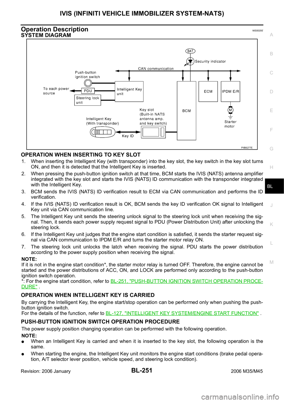
SYSTEM DIAGRAM
OPERATION WHEN INSERTING TO KEY SLOT
1. When inserting the Intelligent Key (with transponder) into the key slot, the key switch in the key slot turns
ON, and then it is detected that the Intelligent Key is inserted.
2. When pressing the push-button ignition switch at that time, BCM starts the IVIS (NATS) antenna amplifier
integrated with the key slot and starts the IVIS (NATS) ID communication with the transponder integrated
with the Intelligent Key.
3. BCM sends the IVIS (NATS) ID verification result to ECM via CAN communication and performs the ID
verification.
4. If the IVIS (NATS) ID verification result is OK, BCM sends the key ID verification OK signal to Intelligent
Key unit via CAN communication line.
5. The Intelligent Key unit sends the steering unlock signal to the steering lock unit when receiving the sig-
nal. Then, it sends each power supply request signal to PDU (Power Distribution Unit) after unlocking the
steering lock.
6. If the Intelligent Key unit judges that the engine start condition is satisfied, it sends the starter request sig-
nal via CAN communication to IPDM E/R and turns the starter motor relay ON.
7. The steering lock unit unlocks the latch when receiving the signal. PDU starts the power distribution
according to the power supply position when receiving the signal.
NOTE:
If it is not in the engine start condition*, the starter motor relay is turned OFF. Therefore, the engine cannot be
started and the power distributions of ACC, ON, and LOCK are performed only according to the push-button
ignition switch operation.
*: For the engine start condition, refer to BL-251, "
PUSH-BUTTON IGNITION SWITCH OPERATION PROCE-
DURE" .
OPERATION WHEN INTELLIGENT KEY IS CARRIED
By carrying the Intelligent Key, the engine start/stop operation can be performed only when pushing the push-
button ignition switch.
For the details of the function, refer to BL-127, "
INTELLIGENT KEY SYSTEM/ENGINE START FUNCTION" .
PUSH-BUTTON IGNITION SWITCH OPERATION PROCEDURE
The power supply position changing operation can be performed with the following operation.
NOTE:
When an Intelligent Key is carried and when it is inserted to the key slot, the following operation is the
same.
When starting the engine, the Intelligent Key unit monitors the engine start conditions (brake pedal opera-
tion, A/T selector lever position, vehicle speed, and steering lock condition).
PIIB6277E
Page 1191 of 5621

BL-252
IVIS (INFINITI VEHICLE IMMOBILIZER SYSTEM-NATS)
Revision: 2006 January2006 M35/M45
Unless each start condition is fulfilled, the engine will not response regardless of how many times the
push-button ignition switch is pushed. At that time, illumination repeats the position in the order of LOCK
ACC ON LOCK.
*1: When the A/T selector lever position is N position, the engine start condition is different according to the vehicle speed.
At vehicle speed of 5 km/h or less, the engine can start only when the brake pedal is depressed.
At vehicle speed of 5 km/h or more, the engine can start even if the brake pedal is not depressed. (It is the same as “Engine stall
return operation while driving”.)
*2: When the A/T selector lever position is in any position other than P position and when the vehicle speed is 5 km/h or more, the
engine stop condition is different.
Press and hold the push-button ignition switch for 2 seconds or more. (When the push-button ignition switch is pressed for too short
a time, the operation may be invalid, so properly press and hold to prevent the incorrect operation.)
Press the push-button ignition switch 3 times within 1.5 seconds. (Emergency stop operation)
ECM Re-Communicating FunctionNIS0020F
Performing following procedure can automatically perform re-communication of ECM and BCM or Intelligent
Key unit, but only when the ECM has been replaced with a new one (*1).
*1: New one means a virgin ECM which has never been energized on-board.
(In this step, initialization procedure by CONSULT-II is not necessary)
NOTE:
When registering new Key IDs or replacing the ECM other than brand new, refer to CONSULT-II
Operation Manual NATS-IVIS/NVIS.
If multiple keys are attached to the key holder, separate them before work.
Distinguish keys with unregistered key ID from those with registered ID.
1. Install ECM.
2. Insert the registered Intelligent Key (*2), turn ignition switch to “ON”.
*2: To perform this step, use the key that has been used before performing ECM replacement.
3. Maintain ignition switch in “ON” position for at least 5 seconds.
4. Turn ignition switch to “OFF”.
Power supply positionEngine start/stop condition
Engine switch operation fre-
quency
Brake pedal A/T selector lever position
LOCK
ACCNot depressed
(When A/T selector lever is in
any position other than P or N,
there will be no effect even if it
is depressed.)Any position other than P or N
(When the brake pedal is not
depressed, there will be no
effect even if the A/T selector
lever is in P or N position.)1
LOCK
ACC ONNot depressed
(When A/T selector lever is in
any position other than P or N,
there will be no effect even if it
is depressed.)Any position other than P or N
(When the brake pedal is not
depressed, there will be no
effect even if the A/T selector
lever is in P or N position.)2
LOCK
ACC ON LOCKNot depressed
(When A/T selector lever is in
any position other than P or N,
there will be no effect even if it
is depressed.)Any position other than P or N
(When the brake pedal is not
depressed, there will be no
effect even if the A/T selector
lever is in P or N position.)3
LOCK
START
ACC
START
ON
START
(Engine start)Depressed P or N position (*1)1
[If the switch is pushed once,
the engine starts from any
power supply position (LOCK,
ACC, and ON)]
Engine start condition
LOCK
(Engine stop)— P position 1
Engine start condition
ACC
(Engine stop)— Any position other than P (*2) 1
Engine stall return operation
while driving—N position 1
Page 1203 of 5621

BL-264
IVIS (INFINITI VEHICLE IMMOBILIZER SYSTEM-NATS)
Revision: 2006 January2006 M35/M45
Terminals and Reference Value for Intelligent Key UnitNIS0020I
Te r m i -
nal
No.Wire
colorItemCondition
Voltage (V)
(Approx.) Push-
button
ignition
switch
positionOperation or conditions
1 SB Power source (fuse) — — Battery voltage
3YIPDM E/R current sig-
nalSTART At starter motor cranking 5
LOCK Any condition other than above 2
8WPush-button ignition
switch LOCK indicatorLOCKPower supply position is in LOCK
position0
—Power supply position is in any posi-
tion other than LOCK1.2
9LPush-button ignition
switch ACC indicatorACCPower supply position is in ACC posi-
tion0
—Power supply position is in any posi-
tion other than ACC1.2
10 VPush-button ignition
switch ON indicatorONPower supply position is in ON posi-
tion0
—Power supply position is in any posi-
tion other than ON1.2
11 P Stop lamp switch —Brake pedal depressed Battery voltage
Brake pedal released Battery voltage
12 L/RPush-button ignition
switch illumination—Push-button ignition switch illumina-
tion is turned on2.6
Push-button ignition switch illumina-
tion is turned off
(15 seconds or more after the driver
door is closed)0
13 LG/B Key slot illumination LOCKDriver door is opened under the condi-
tion that the Intelligent Key is inserted
into the key slot0
Battery voltage 0
Intelligent Key is removed from key
slot (when key slot illumination is
turned off)0
15 LGSteering lock unit
power sourceLOCK — Battery voltage
16 P/BSteering lock unit sig-
nalLOCK Steering lock: Lock Battery voltage
ACCSteering lock: Unlock
(Unlocked moment)0
17 OSteering lock unit con-
dition signal-1LOCK Steering lock: Lock 0
ACC
Steering lock: UnlockBattery voltage
ON Battery voltage
18 L/YSteering lock unit con-
dition signal-2LOCK Steering lock: Lock Battery voltage
ACC
Steering lock: Unlock0
ON 0
19 BR/Y Key switch LOCKIntelligent Key is inserted into key slot Battery voltage
Intelligent Key is removed from key
slot0
20 B Ground — — 0
Page 1204 of 5621

IVIS (INFINITI VEHICLE IMMOBILIZER SYSTEM-NATS)
BL-265
C
D
E
F
G
H
J
K
L
MA
B
BL
Revision: 2006 January2006 M35/M45
27 VA/T device (Detention
switch)LOCK A/T selector lever is in P position 0
ONA/T selector lever is in any position
other than PBattery voltage
28 SB Starter relayON A/T selector lever is in N or P position Battery voltage
—Power supply position is in LOCK
position or A/T selector lever is in any
position other than N or P position0
29 V/R Stop lamp switch —Brake pedal depressed Battery voltage
Brake pedal released 0
30 L/WIgnition power supply
(ACC)ACCPower supply position is in ACC posi-
tionBattery voltage
31 GRIgnition power supply
(ON)ONPower supply position is in ON posi-
tionBattery voltage
33 O PDU signalLOCK Steering lock: Lock 0
ACC Steering lock: Unlock 8
34 R PDU feed back signal LOCK At wake-up (Open driver door) 0
35 LG Vehicle speed signal ONAt speedometer operation (vehicle
speed approx. 40 km/h)
37 P CAN L — — —
38 L CAN H — — —
39 BR/WPush-button ignition
switch—Push-button ignition switch is pressed 0
Push-button ignition switch is released Battery voltage
40 B Ground — — 0
41 Y Power source (fuse) — — Battery voltage
42 P PDU wake up signalLOCKAt sleep (30 seconds or more after all
doors are closed under the condition
that the power supply position is in the
LOCK position)Battery voltage
— At wake-up (Open driver door) 0
43 G Starter signalON At starter motor cranking 0
— Other than above Battery voltage
46 V PDU signal— Steering lock: Lock Battery voltage
LOCK Steering lock: Unlocked moment 0
56 B Ground — — 0
57 L Power source (fuse) — — Battery voltage
58 OA/T device (Detention
switch)LOCKAt sleep (30 seconds or more after all
doors are closed under the condition
that the power supply position is in the
LOCK position)0
— At wake-up (Open driver door) Battery voltage Te r m i -
nal
No.Wire
colorItemCondition
Voltage (V)
(Approx.) Push-
button
ignition
switch
positionOperation or conditions
PKIA1935E
Page 1282 of 5621

BRAKE PEDAL
BR-7
C
D
E
G
H
I
J
K
L
MA
B
BR
Revision: 2006 January2006 M35/M45
ADJUSTMENT
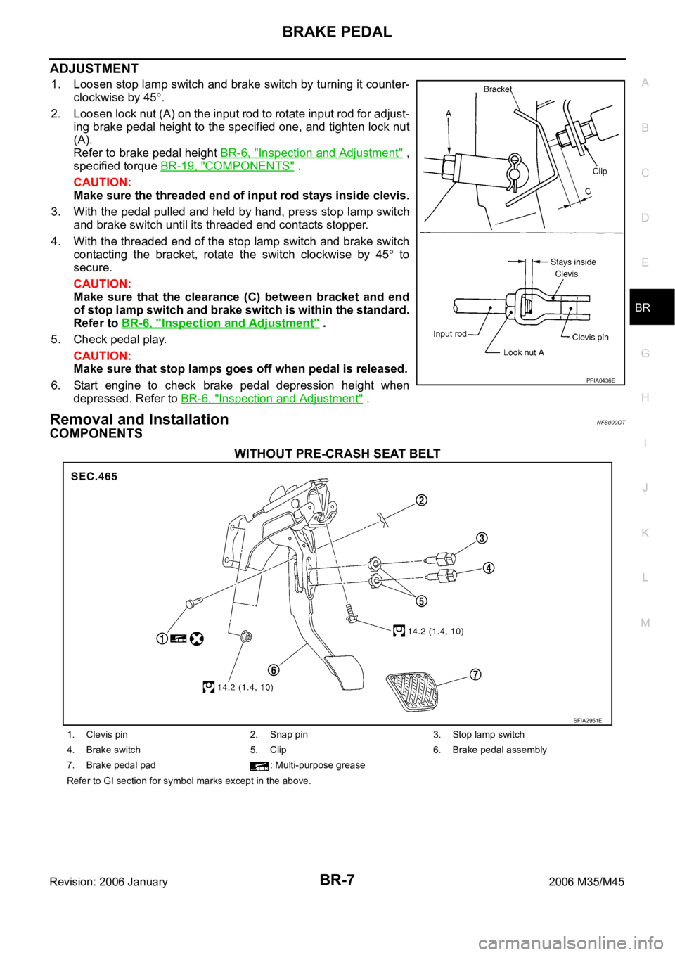
1. Loosen stop lamp switch and brake switch by turning it counter-
clockwise by 45
.
2. Loosen lock nut (A) on the input rod to rotate input rod for adjust-
ing brake pedal height to the specified one, and tighten lock nut
(A).
Refer to brake pedal height BR-6, "
Inspection and Adjustment" ,
specified torque BR-19, "
COMPONENTS" .
CAUTION:
Make sure the threaded end of input rod stays inside clevis.
3. With the pedal pulled and held by hand, press stop lamp switch
and brake switch until its threaded end contacts stopper.
4. With the threaded end of the stop lamp switch and brake switch
contacting the bracket, rotate the switch clockwise by 45
to
secure.
CAUTION:
Make sure that the clearance (C) between bracket and end
of stop lamp switch and brake switch is within the standard.
Refer to BR-6, "
Inspection and Adjustment" .
5. Check pedal play.
CAUTION:
Make sure that stop lamps goes off when pedal is released.
6. Start engine to check brake pedal depression height when
depressed. Refer to BR-6, "
Inspection and Adjustment" .
Removal and InstallationNFS000OT
COMPONENTS
WITHOUT PRE-CRASH SEAT BELT
PFIA0436E
SFIA2951E
1. Clevis pin 2. Snap pin 3. Stop lamp switch
4. Brake switch 5. Clip 6. Brake pedal assembly
7. Brake pedal pad : Multi-purpose grease
Refer to GI section for symbol marks except in the above.
Page 1293 of 5621

BR-18
BRAKE BOOSTER
Revision: 2006 January2006 M35/M45
BRAKE BOOSTERPFP:47200
On-Board Inspection and ServiceNFS000P6
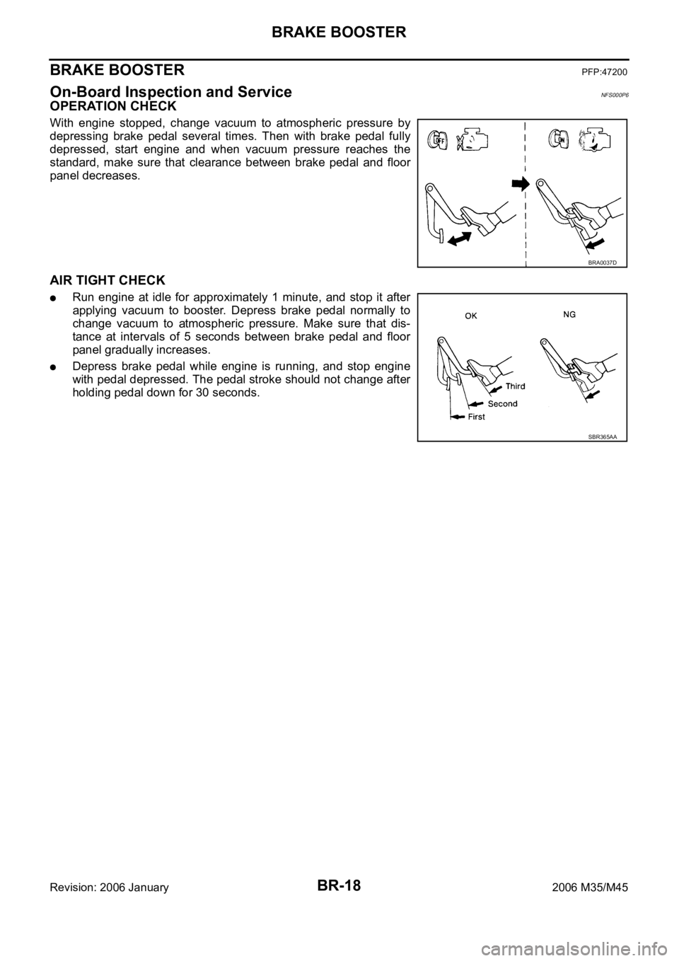
OPERATION CHECK
With engine stopped, change vacuum to atmospheric pressure by
depressing brake pedal several times. Then with brake pedal fully
depressed, start engine and when vacuum pressure reaches the
standard, make sure that clearance between brake pedal and floor
panel decreases.
AIR TIGHT CHECK
Run engine at idle for approximately 1 minute, and stop it after
applying vacuum to booster. Depress brake pedal normally to
change vacuum to atmospheric pressure. Make sure that dis-
tance at intervals of 5 seconds between brake pedal and floor
panel gradually increases.
Depress brake pedal while engine is running, and stop engine
with pedal depressed. The pedal stroke should not change after
holding pedal down for 30 seconds.
BRA0037D
SBR365AA
Page 1315 of 5621
![INFINITI M35 2006 Factory Service Manual BRC-4
[VDC/TCS/ABS]
PRECAUTIONS
Revision: 2006 January2006 M35/M45
Precautions for Brake ControlNFS000Q1
Just after starting vehicle after ignition switch ON, brake pedal may vibrate or motor operatin INFINITI M35 2006 Factory Service Manual BRC-4
[VDC/TCS/ABS]
PRECAUTIONS
Revision: 2006 January2006 M35/M45
Precautions for Brake ControlNFS000Q1
Just after starting vehicle after ignition switch ON, brake pedal may vibrate or motor operatin](/manual-img/42/57023/w960_57023-1314.png)
BRC-4
[VDC/TCS/ABS]
PRECAUTIONS
Revision: 2006 January2006 M35/M45
Precautions for Brake ControlNFS000Q1
Just after starting vehicle after ignition switch ON, brake pedal may vibrate or motor operating noise may
be heard from engine compartment. This is normal condition.
When an error is indicated by ABS or another warning lamp, collect all necessary information from cus-
tomer (what symptoms are present under what conditions) and check for simple causes before starting
diagnostic servicing. Besides electrical system inspection, check brake booster operation, brake fluid
level, and oil leaks.
If tire size and type are used in an improper combination, or brake pads are not Genuine NISSAN parts,
stopping distance or steering stability may deteriorate.
ABS might be out of order or malfunctions by putting a radio (wiring inclusive), an antenna and a lead-in
wire near the control unit.
If aftermarket parts (car stereo, CD player, etc.) have been installed, check for incidents such as harness
pinches, open circuits, and improper wiring.
VDC system may not operate normally or a VDC OFF indicator lamp or SLIP indicator lamp may light.
–When replacing the following parts with parts other than genuine parts or making modifications: Suspen-
sion-related parts (shock absorber, spring, bushing, etc.), tires, wheels (other than specified sizes), brake-
related parts (pad, rotor, caliper, etc.), engine-related parts (muffler, ECM, etc.) and body reinforcement-
related parts (roll bar, tower bar, etc.).
–When driving with worn or deteriorated suspension, tires and brake-related parts.