2006 INFINITI M35 stop start
[x] Cancel search: stop startPage 950 of 5621

SQUEAK AND RATTLE TROUBLE DIAGNOSIS
BL-11
C
D
E
F
G
H
J
K
L
MA
B
BL
Revision: 2006 January2006 M35/M45
INSULATOR (Light foam block)
80845-71L00: 30 mm (1.18 in) thick, 30
50 mm (1.181.97 in)
FELT CLOTHTAPE
Used to insulate where movement does not occur. Ideal for instrument panel applications.
68370-4B000: 15
25 mm (0.590.98 in) pad/68239-13E00: 5 mm (0.20 in) wide tape roll
The following materials, not found in the kit, can also be used to repair squeaks and rattles.
UHMW (TEFLON) TAPE
Insulates where slight movement is present. Ideal for instrument panel applications.
SILICONE GREASE
Used in place of UHMW tape that will be visible or not fit. Will only last a few months.
SILICONE SPRAY
Use when grease cannot be applied.
DUCT TAPE
Use to eliminate movement.
CONFIRM THE REPAIR
Confirm that the cause of a noise is repaired by test driving the vehicle. Operate the vehicle under the same
conditions as when the noise originally occurred. Refer to the notes on the Diagnostic Worksheet.
Generic Squeak and Rattle TroubleshootingNIS001WH
Refer to Table of Contents for specific component removal and installation information.
INSTRUMENT PANEL
Most incidents are caused by contact and movement between:
1. The cluster lid A and instrument panel
2. Acrylic lens and combination meter housing
3. Instrument panel to front pillar garnish
4. Instrument panel to windshield
5. Instrument panel mounting pins
6. Wiring harnesses behind the combination meter
7. A/C defroster duct and duct joint
These incidents can usually be located by tapping or moving the components to duplicate the noise or by
pressing on the components while driving to stop the noise. Most of these incidents can be repaired by apply-
ing felt cloth tape or silicon spray (in hard to reach areas). Urethane pads can be used to insulate wiring har-
ness.
CAUTION:
Do not use silicone spray to isolate a squeak or rattle. If you saturate the area with silicone, you will
not be able to recheck the repair.
CENTER CONSOLE
Components to pay attention to include:
1. Shifter assembly cover to finisher
2. A/C control unit and cluster lid C
3. Wiring harnesses behind audio and A/C control unit
The instrument panel repair and isolation procedures also apply to the center console.
DOORS
Pay attention to the:
1. Finisher and inner panel making a slapping noise
2. Inside handle escutcheon to door finisher
3. Wiring harnesses tapping
4. Door striker out of alignment causing a popping noise on starts and stops
Tapping or moving the components or pressing on them while driving to duplicate the conditions can isolate
many of these incidents. You can usually insulate the areas with felt cloth tape or insulator foam blocks from
the Nissan Squeak and Rattle Kit (J-43980) to repair the noise.
Page 993 of 5621

BL-54
INTELLIGENT KEY SYSTEM
Revision: 2006 January2006 M35/M45
Keyless Power Window Down (Open) Function
All power windows open when the unlock button on Intelligent Key is activated and kept pressed for more than
3 seconds with the ignition switch OFF. The windows keep opening if the unlock button is continuously
pressed.
The power window opening stops when the following operations are performed:
When the unlock button is kept pressed more than 15 seconds.
When the ignition switch is turned ON while the power window opening is operated.
When the unlock button is released.
While retained power operation activate, Keyless power window down (open) Function cannot be operated.
Keyless power window down operation mode can be changed by “P/W DOWN DELAY” mode in “WORK SUP-
PORT”. Refer to BL-83, "
WORK SUPPORT" .
Room Lamp Illumination Operation
When the following conditions are met:
Condition of interior lamp switch is in DOOR position
Door switch OFF (all the doors are closed)
Intelligent Key system turns on interior lamp (for 30 seconds) by receiving UNLOCK signal from Intelligent
Key. For detailed description, refer to LT- 2 7 0 , "
ROOM LAMP TIMER OPERATION" .
List of Operation Related Parts
Parts marked with are the parts related to operation.
ENGINE START FUNCTION
Refer to BL-127, "INTELLIGENT KEY SYSTEM/ENGINE START FUNCTION" .
Remote keyless entry functions
Intelligent Key
Key slot
Door request switch (Driver, Passenger)
Door switch
Trunk room lamp switch
Door lock actuator
Trunk lid opener actuator
Intelligent Key warning buzzer
Intelligent Key unit
CAN communication system
BCM
Combination meter
Hazard warning lamp
Horn
IPDM E/R
Head lamp
Door lock/unlock function by remote control button
Trunk open function by remote control button
Hazard and horn reminder function
Selective unlock function
Keyless power window down (open) function
Auto door lock function
Panic alarm function
Page 996 of 5621

INTELLIGENT KEY SYSTEM
BL-57
C
D
E
F
G
H
J
K
L
MA
B
BL
Revision: 2006 January2006 M35/M45
Warning Method
The following table shows the alarm or warning methods with chime.
Meter display, “KEY” indicator or key slot illumination when the warning conditions are met.
Engine start informationIgnition switch is ON
position
Ignition switch: ON position.
Shift position: P position
Engine is stopped
Ignition switch is except
ON position
Ignition switch: Except ON position.
Shift position: P position
Intelligent Key is inserted in key slot.
Intelligent Key can be detected inside the vehicle.
Steering lock information When steering lock can not be released after ignition switch is turned ON.
Intelligent Key low battery warningWhen Intelligent Key is low battery, Intelligent Key unit is detected after igni-
tion switch is turned ON.
Key ID warningWhen registered Intelligent Key can not be detected inside the vehicle after
ignition switch is turned ON. Warning/Information functions Operation procedure
Warning/Information functions“KEY” warn-
ing lampCombination meter displayKey slot
illuminationWarning chime
Combination
meter buzzerIntelligent
Key warning
buzzer
Intelligent Key system malfunction Illuminate — — — —
OFF position warn-
ing For internal — — — Activate —
For external — — — — Activate
P position warning — — Activate —
ACC warning — — Activate —
Take away warningDoor is open to
close— Flash Activate Activate
Door is open — Flash — —
Push-ignition
switch operation— Flash Activate —
Ta k e a w a y
through window— Flash Activate —
Intelligent Key is
removed from
key slot—Flash——
Door lock opera-
tion warningRequest switch
operation————Activate
Intelligent Key
operation————Activate
PIIB4765J
PIIB4766J
PIIB6452E
Page 1019 of 5621

BL-80
INTELLIGENT KEY SYSTEM
Revision: 2006 January2006 M35/M45
15. CHECK OUT
CHECK OUT.
>> INSPECTION END
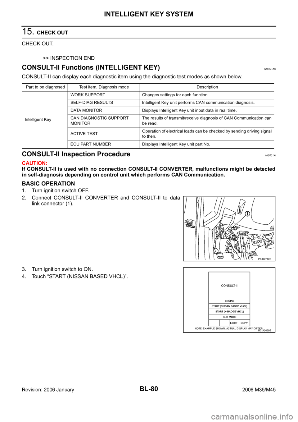
CONSULT-II Functions (INTELLIGENT KEY)NIS001XH
CONSULT-II can display each diagnostic item using the diagnostic test modes as shown below.
CONSULT-II Inspection ProcedureNIS001XI
CAUTION:
If CONSULT-II is used with no connection CONSULT-II CONVERTER, malfunctions might be detected
in self-diagnosis depending on control unit which performs CAN Communication.
BASIC OPERATION
1. Turn ignition switch OFF.
2. Connect CONSULT-II CONVERTER and CONSULT-II to data
link connector (1).
3. Turn ignition switch to ON.
4. Touch “START (NISSAN BASED VHCL)”.
Part to be diagnosed Test item, Diagnosis mode Description
Intelligent KeyWORK SUPPORT Changes settings for each function.
SELF-DIAG RESULTS Intelligent Key unit performs CAN communication diagnosis.
DATA MONITOR Displays Intelligent Key unit input data in real time.
CAN DIAGNOSTIC SUPPORT
MONITORThe results of transmit/receive diagnosis of CAN Communication can
be read.
ACTIVE TESTOperation of electrical loads can be checked by sending driving signal
to then.
ECU PART NUMBER Displays Intelligent Key unit part No.
PBIB2712E
BCIA0029E
Page 1021 of 5621
![INFINITI M35 2006 Factory Service Manual BL-82
INTELLIGENT KEY SYSTEM
Revision: 2006 January2006 M35/M45
CAUTION:
When CAN COMM 1 [U1000] and CAN COMM 2 [U1010] are displayed, give priority to performing trouble diagnosis.
DATA MONITOR
INTEL INFINITI M35 2006 Factory Service Manual BL-82
INTELLIGENT KEY SYSTEM
Revision: 2006 January2006 M35/M45
CAUTION:
When CAN COMM 1 [U1000] and CAN COMM 2 [U1010] are displayed, give priority to performing trouble diagnosis.
DATA MONITOR
INTEL](/manual-img/42/57023/w960_57023-1020.png)
BL-82
INTELLIGENT KEY SYSTEM
Revision: 2006 January2006 M35/M45
CAUTION:
When CAN COMM 1 [U1000] and CAN COMM 2 [U1010] are displayed, give priority to performing trouble diagnosis.
DATA MONITOR
INTELLIGENT KEY
[B2552]Internal malfunction is detected in Intelligent Key unitReplace Intelligent Key
unit.BL-163
IGN POWER CIRCUIT
[B2553]It continues for 2 seconds or more that ON power sup-
ply input to Intelligent Key unit is excessively low when
the power supply position is in ON positionCheck Intelligent Key
unit ON power supply
inputBL-163
ACC POWER CIRCUIT
[B2554]It continues for 2 seconds or more that ACC power
supply input to Intelligent Key unit is excessively low
when the power supply position is in ACC or ON posi-
tionCheck Intelligent Key
unit ACC power supply
inputBL-164
STOP LAMP CIRCUIT
[B2555]5V or less is detected at both the stop lamp switch sig-
nal input circuit that is input to Intelligent Key unit and
the monitor input before stop lamp switchCheck stop lamp switchBL-167
ENG START SW
[B2556]Condition that push-button ignition switch is pushed is
detected continuously for 100 seconds or moreCheck push-button igni-
tion switchBL-168
VEHICLE SPEED
[B2557]Some differences occur on one or more vehicle speed
inputs of Intelligent Key unitCheck vehicle speed sig-
nalBL-169
SHIFT POSITION
[B2558]
There is a difference between the shift position input
via CAN communication and the P position input by
detent switch
Vehicle speed (5 km/h or more) is detected continu-
ously for 10 seconds or more even if the shift posi-
tion is detected in P position when the power supply
position is in ON positionCheck shift position inputBL-172
PDU
[B2559]Internal malfunction is detected in PDU Replace PDUBL-174
START POW SUP CIRC
[B2560]Though the engine start operation is not performed,
starter relay in IPDM E/R is ONCheck starter power sup-
plyBL-174
LOW VOLTAGE
[B2562]Battery power supply input to Intelligent Key unit (8.8V
or less) is detected continuously for 1.5 seconds or
moreCheck battery low volt-
ageBL-177
HI VOLTAGE
[B2563]Battery power supply input to Intelligent Key unit (18V
or more) is detected continuously for 90 seconds or
moreCheck for battery high
voltageBL-178
NATS MALFUNCTION
[B2590]Malfunction is detected in immobilizer systemCheck (IVIS) NATS trou-
ble diagnosis procedureBL-248
Suspect Systems
[DTC]Diagnostic item is detected when... Repair work Reference page
Monitor item Content
DR REQ SW Indicates [ON/OFF] condition of door request switch (driver side).
AS REQ SW Indicates [ON/OFF] condition of door request switch (passenger side).
BD/TR REQ SW Indicates [ON/OFF] condition of trunk opener request switch.
ON POS Indicates [ON/OFF] condition of ignition switch in ON position.
ACC POS Indicates [ON/OFF] condition of ignition switch in ACC position.
DOOR STAT SW Indicates [ON/OFF] condition of door unlock sensor.
STOP LAMP SW Indicates [ON/OFF] condition of stop lamp switch.
P RANGE SW Indicates [ON/OFF] condition of park position switch.
TR CANCEL SW* Indicates [ON/OFF] condition of trunk cancel switch.
DOOR LOCK SIG* Indicates [ON/OFF] condition of door lock signal from Intelligent Key remote controller button.
DOOR UNLOCK SIG* Indicates [ON/OFF] condition of door unlock signal from Intelligent Key remote controller button.
KEYLESS TRUNK* Indicates [ON/OFF] condition of trunk open signal from Intelligent Key remote controller button.
Page 1066 of 5621

INTELLIGENT KEY SYSTEM/ENGINE START FUNCTION
BL-127
C
D
E
F
G
H
J
K
L
MA
B
BL
Revision: 2006 January2006 M35/M45
INTELLIGENT KEY SYSTEM/ENGINE START FUNCTIONPFP:285F1
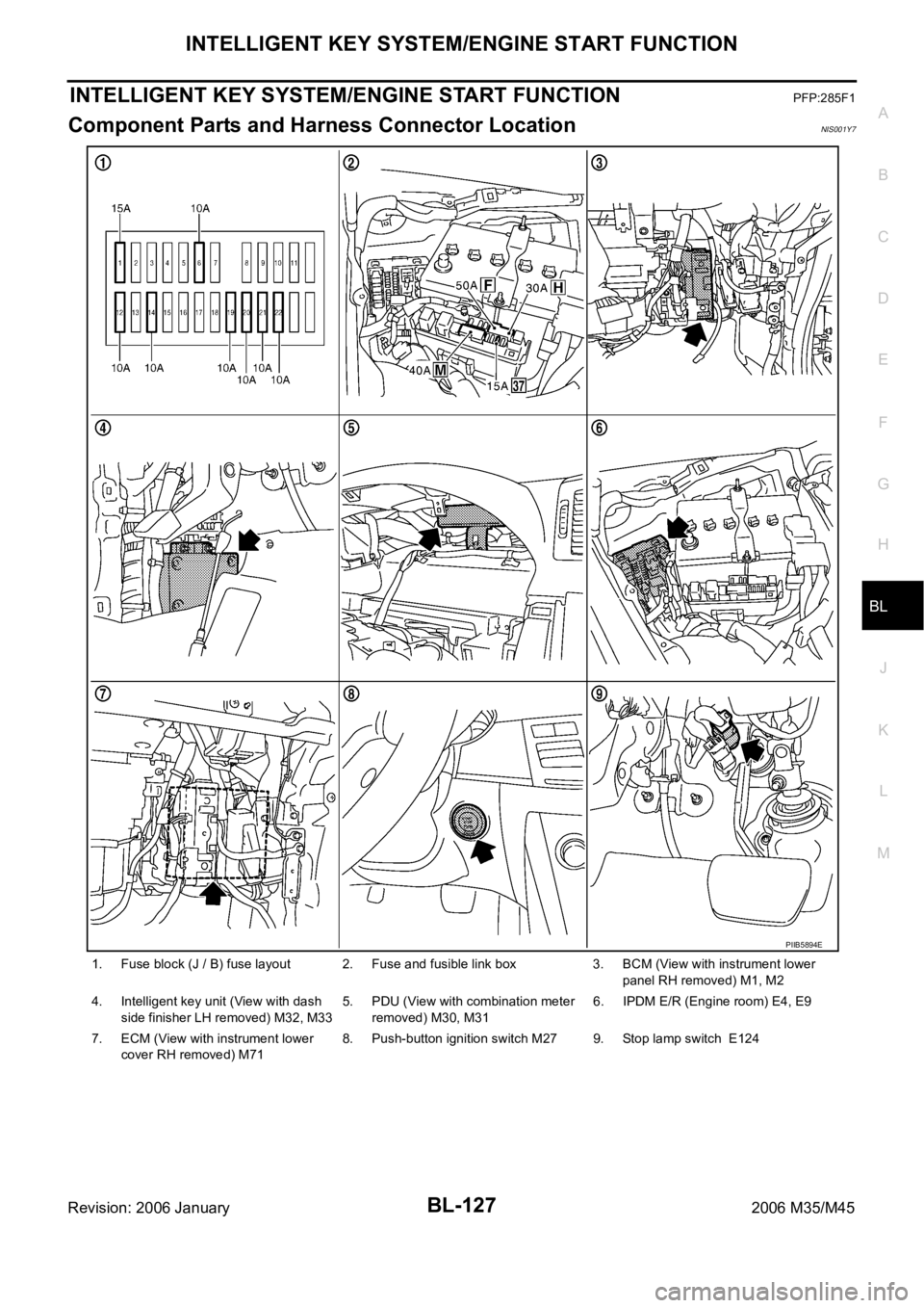
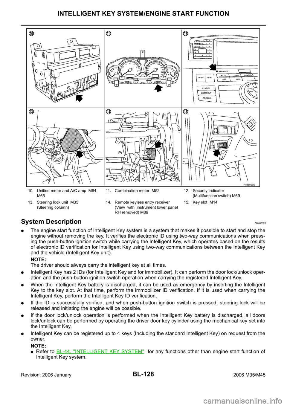
Component Parts and Harness Connector LocationNIS001Y7
1. Fuse block (J / B) fuse layout 2. Fuse and fusible link box 3. BCM (View with instrument lower
panel RH removed) M1, M2
4. Intelligent key unit (View with dash
side finisher LH removed) M32, M335. PDU (View with combination meter
removed) M30, M316. IPDM E/R (Engine room) E4, E9
7. ECM (View with instrument lower
cover RH removed) M718. Push-button ignition switch M27 9. Stop lamp switch E124
PIIB5894E
Page 1067 of 5621

BL-128
INTELLIGENT KEY SYSTEM/ENGINE START FUNCTION
Revision: 2006 January2006 M35/M45
System DescriptionNIS001Y8
The engine start function of Intelligent Key system is a system that makes it possible to start and stop the
engine without removing the key. It verifies the electronic ID using two-way communications when press-
ing the push-button ignition switch while carrying the Intelligent Key, which operates based on the results
of electronic ID verification for Intelligent Key using two-way communications between the Intelligent Key
and the vehicle (Intelligent Key unit).
NOTE:
The driver should always carry the intelligent key at all times.
Intelligent Key has 2 IDs (for Intelligent Key and for immobilizer). It can perform the door lock/unlock oper-
ation and the push-button ignition switch operation when carrying the registered Intelligent Key.
When the Intelligent Key battery is discharged, it can be used as emergency by inserting the Intelligent
Key to the key slot. At that time, perform the immobilizer ID verification. If it is used when carrying the
Intelligent Key, perform the Intelligent Key ID verification.
If the ID is successfully verified, and when push-button ignition switch is pressed, steering lock will be
released and initiating the engine will be possible.
If the door lock/unlock operation is performed when the Intelligent Key battery is discharged, all doors
lock/unlock can be performed by operating the driver door key cylinder using the mechanical key set into
the Intelligent Key.
Intelligent Key can be registered up to 4 keys (Including the standard Intelligent Key) on request from the
owner.
NOTE:
Refer to BL-44, "INTELLIGENT KEY SYSTEM" for any functions other than engine start function of
Intelligent Key system.
10. Unified meter and A/C amp M64,
M6511. Combination meter M52 12. Security indicator
(Multifunction switch) M69
13. Steering lock unit M35
(Steering column)14. Remote keyless entry receiver
(View with instrument lower panel
RH removed) M89 15. Key slot M14
PIIB5896E
Page 1068 of 5621

INTELLIGENT KEY SYSTEM/ENGINE START FUNCTION
BL-129
C
D
E
F
G
H
J
K
L
MA
B
BL
Revision: 2006 January2006 M35/M45
PRECAUTIONS FOR INTELLIGENT KEY SYSTEM
In the Intelligent Key system of model Y50, the transponder (the chip for immobilizer ID verifica-
tion) is integrated into the Intelligent Key. (For the conventional models, it is integrated into the
mechanical key.) Therefore, the mechanical key cannot perform the ID verification, and thus it can-
not start the engine. Instead of it, the immobilizer ID verification can be performed by inserting the
Intelligent Key into the key slot, and then it can start the engine.
When registering the Intelligent Key, 2 registration procedures (immobilizer ID registration and
Intelligent Key ID registration) should be performed. The immobilizer ID registration is the proce-
dure that registers the ID stored into the transponder (integrated into Intelligent Key) to the BCM.
The Intelligent Key ID registration is the procedure that registers the ID to the Intelligent Key unit.
Each registration is a different procedure.
When performing the Intelligent Key ID registration only, the engine cannot be started by inserting
the key into the key slot. When performing the engine immobilizer ID registration only, the engine
cannot be started by the operation when carrying the key. The registrations of both systems
should be performed.
Operation DescriptionNIS001Y9
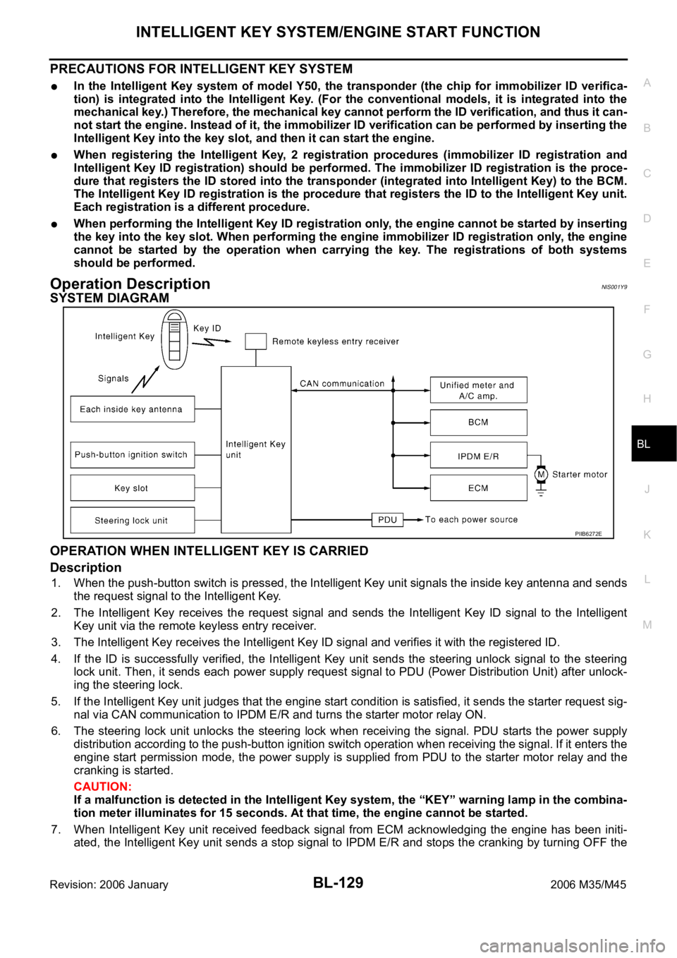
SYSTEM DIAGRAM
OPERATION WHEN INTELLIGENT KEY IS CARRIED
Description
1. When the push-button switch is pressed, the Intelligent Key unit signals the inside key antenna and sends
the request signal to the Intelligent Key.
2. The Intelligent Key receives the request signal and sends the Intelligent Key ID signal to the Intelligent
Key unit via the remote keyless entry receiver.
3. The Intelligent Key receives the Intelligent Key ID signal and verifies it with the registered ID.
4. If the ID is successfully verified, the Intelligent Key unit sends the steering unlock signal to the steering
lock unit. Then, it sends each power supply request signal to PDU (Power Distribution Unit) after unlock-
ing the steering lock.
5. If the Intelligent Key unit judges that the engine start condition is satisfied, it sends the starter request sig-
nal via CAN communication to IPDM E/R and turns the starter motor relay ON.
6. The steering lock unit unlocks the steering lock when receiving the signal. PDU starts the power supply
distribution according to the push-button ignition switch operation when receiving the signal. If it enters the
engine start permission mode, the power supply is supplied from PDU to the starter motor relay and the
cranking is started.
CAUTION:
If a malfunction is detected in the Intelligent Key system, the “KEY” warning lamp in the combina-
tion meter illuminates for 15 seconds. At that time, the engine cannot be started.
7. When Intelligent Key unit received feedback signal from ECM acknowledging the engine has been initi-
ated, the Intelligent Key unit sends a stop signal to IPDM E/R and stops the cranking by turning OFF the
PIIB6272E