2006 INFINITI M35 charging
[x] Cancel search: chargingPage 4806 of 5621
CHASSIS AND BODY MAINTENANCE
MA-29
C
D
E
F
G
H
I
J
K
MA
B
MA
Revision: 2006 January2006 M35/M45
CHASSIS AND BODY MAINTENANCEPFP:00100
Checking Exhaust SystemNLS0007Z
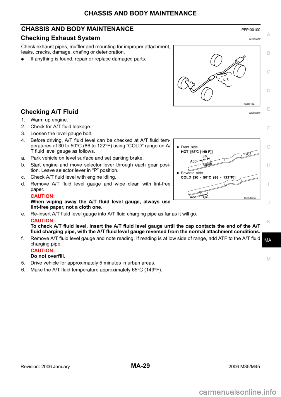
Check exhaust pipes, muffler and mounting for improper attachment,
leaks, cracks, damage, chafing or deterioration.
If anything is found, repair or replace damaged parts.
Checking A/T FluidNLS00080
1. Warm up engine.
2. Check for A/T fluid leakage.
3. Loosen the level gauge bolt.
4. Before driving, A/T fluid level can be checked at A/T fluid tem-
peratures of 30 to 50
C (86 to 122F) using “COLD” range on A/
T fluid level gauge as follows.
a. Park vehicle on level surface and set parking brake.
b. Start engine and move selector lever through each gear posi-
tion. Leave selector lever in “P” position.
c. Check A/T fluid level with engine idling.
d. Remove A/T fluid level gauge and wipe clean with lint-free
paper.
CAUTION:
When wiping away the A/T fluid level gauge, always use
lint-free paper, not a cloth one.
e. Re-insert A/T fluid level gauge into A/T fluid charging pipe as far as it will go.
CAUTION:
To check A/T fluid level, insert the A/T fluid level gauge until the cap contacts the end of the A/T
fluid charging pipe, with the A/T fluid level gauge reversed from the normal attachment conditions.
f. Remove A/T fluid level gauge and note reading. If reading is at low side of range, add ATF to the A/T fluid
charging pipe.
CAUTION:
Do not overfill.
5. Drive vehicle for approximately 5 minutes in urban areas.
6. Make the A/T fluid temperature approximately 65
C (149F).
SMA211A
SCIA4835E
Page 4807 of 5621
MA-30
CHASSIS AND BODY MAINTENANCE
Revision: 2006 January2006 M35/M45
NOTE:
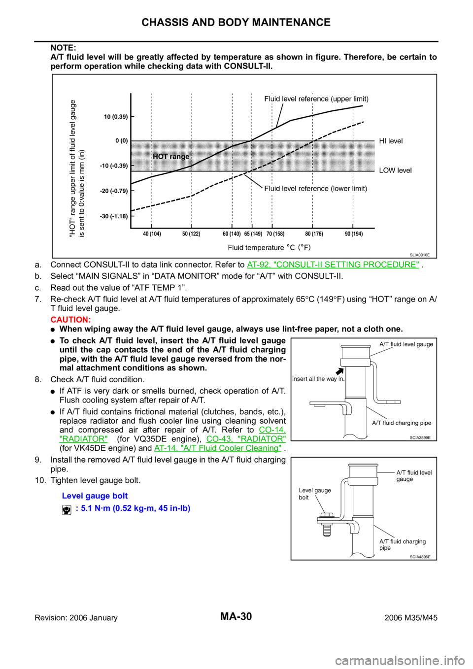
A/T fluid level will be greatly affected by temperature as shown in figure. Therefore, be certain to
perform operation while checking data with CONSULT-II.
a. Connect CONSULT-II to data link connector. Refer to AT-92, "
CONSULT-II SETTING PROCEDURE" .
b. Select “MAIN SIGNALS” in “DATA MONITOR” mode for “A/T” with CONSULT-II.
c. Read out the value of “ATF TEMP 1”.
7. Re-check A/T fluid level at A/T fluid temperatures of approximately 65
C (149F) using “HOT” range on A/
T fluid level gauge.
CAUTION:
When wiping away the A/T fluid level gauge, always use lint-free paper, not a cloth one.
To check A/T fluid level, insert the A/T fluid level gauge
until the cap contacts the end of the A/T fluid charging
pipe, with the A/T fluid level gauge reversed from the nor-
mal attachment conditions as shown.
8. Check A/T fluid condition.
If ATF is very dark or smells burned, check operation of A/T.
Flush cooling system after repair of A/T.
If A/T fluid contains frictional material (clutches, bands, etc.),
replace radiator and flush cooler line using cleaning solvent
and compressed air after repair of A/T. Refer to CO-14,
"RADIATOR" (for VQ35DE engine), CO-43, "RADIATOR"
(for VK45DE engine) and AT- 1 4 , "A/T Fluid Cooler Cleaning" .
9. Install the removed A/T fluid level gauge in the A/T fluid charging
pipe.
10. Tighten level gauge bolt.
Level gauge bolt
: 5.1 Nꞏm (0.52 kg-m, 45 in-lb)
SLIA0016E
SCIA2899E
SCIA4896E
Page 4808 of 5621
CHASSIS AND BODY MAINTENANCE
MA-31
C
D
E
F
G
H
I
J
K
MA
B
MA
Revision: 2006 January2006 M35/M45
Changing A/T FluidNLS00081
1. Warm up ATF.
2. Stop engine.
3. Loosen the level gauge bolt.
4. Drain ATF from drain plug and refill with new ATF. Always refill
same volume with drained ATF.
To replace the ATF, pour in new ATF at the A/T fluid charging
pipe with the engine idling and at the same time drain the old
ATF from the radiator cooler hose return side.
When the color of the ATF coming out is about the same as
the color of the new ATF, the replacement is complete. The
amount of new ATF to use should be 30 to 50% increase of
the stipulated amount.
CAUTION:
Use only Genuine NISSAN Matic J ATF. Do not mix with other ATF.
Using ATF other than Genuine NISSAN Matic J ATF will cause deterioration in driveability and
automatic transmission durability, and may damage the automatic transmission, which is not
covered by the warranty.
When filling ATF, take care not to scatter heat generating parts such as exhaust.
Do not reuse drain plug gasket.
5. Run engine at idle speed for 5 minutes.
6. Check A/T fluid level and condition. Refer to AT- 1 3 , "
Checking A/T Fluid" . If ATF is still dirty, repeat step 2.
through 5.
7. Install the removed A/T fluid level gauge into A/T fluid charging pipe.
8. Tighten the level gauge bolt.
Checking Transfer FluidNLS00082
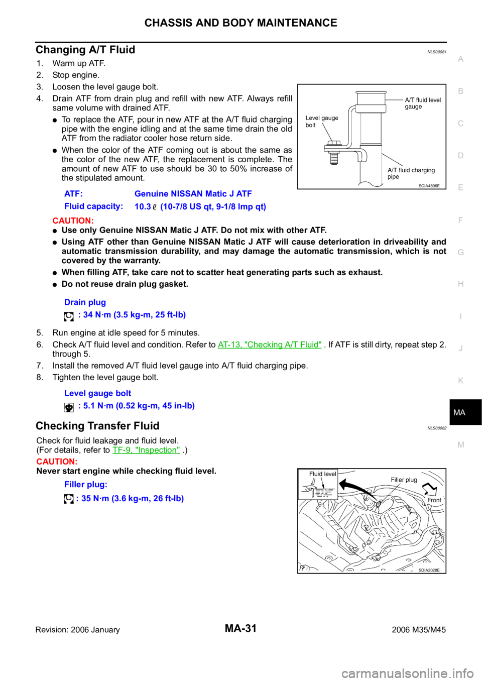
Check for fluid leakage and fluid level.
(For details, refer to TF-9, "
Inspection" .)
CAUTION:
Never start engine while checking fluid level.ATF: Genuine NISSAN Matic J ATF
Fluid capacity:
10.3 (10-7/8 US qt, 9-1/8 lmp qt)
Drain plug
: 34 Nꞏm (3.5 kg-m, 25 ft-lb)
Level gauge bolt
: 5.1 Nꞏm (0.52 kg-m, 45 in-lb)
SCIA4896E
Filler plug:
: 35 Nꞏm (3.6 kg-m, 26 ft-lb)
SDIA2028E
Page 4920 of 5621

HARNESS
PG-93
C
D
E
F
G
H
I
J
L
MA
B
PG
Revision: 2006 January2006 M35/M45
Wiring Diagram Codes (Cell Codes) NKS004ET
Use the chart below to find out what each wiring diagram code stands for.
Refer to the wiring diagram code in the alphabetical index to find the location (page number) of each wiring
diagram.
Code Section Wiring Diagram Name
A/C ATC Air Conditioner
AF1B1 EC Air Fuel Ratio Sensor 1 Bank 1
AF1B2 EC Air Fuel Ratio Sensor 1 Bank 2
AF1HB1 EC Air Fuel Ratio Sensor 1 Heater Bank 1
AF1HB2 EC Air Fuel Ratio Sensor 1 Heater Bank 2
AFS LT Adaptive Front Lighting System
APPS1 EC Accelerator Pedal Position Sensor
APPS2 EC Accelerator Pedal Position Sensor
APPS3 EC Accelerator Pedal Position Sensor
ASC/BS EC Automatic Speed Control Device (ASCD) Brake Switch
ASC/SW EC Automatic Speed Control Device (ASCD) Steering Switch
ASCBOF EC Automatic Speed Control Device (ASCD) Brake Switch
ASCIND EC Automatic Speed Control Device (ASCD) Indicator
AT/IND DI A/T Indicator Lamp
AUT/DP SE Automatic Drive Positioner
AUTO/L LT Automatic Light System
AV AV Audio and Visual System
AWD TF AWD Control System
BACK/L LT Back-Up Lamp
BRK/SW EC Brake Switch
C/SEAT SE Climate Controlled Seat
CAN AT CAN Communication Line
CAN EC CAN Communication Line
CAN LAN CAN System
CHARGE SC Charging System
CHIME DI Warning Chime
CIGAR WW Cigarette Lighter
CLOCK DI Clock
COMBSW LT Combination Switch
COMPAS DI Compass and Thermometer
COOL/F EC Cooling Fan Control
CUR/SE EC Battery Current Sensor
D/LOCK BL Power Door Lock
DEF GW Rear Window Defogger
DTRL LT Headlamp - with Daytime Light System
ECM/PW EC ECM Power Supply for Back-Up
ECTS EC Engine Coolant Temperature Sensor
ENG/ST BL Engine Start System
EPS STC Electric Controlled Power Steering System
ETC1 EC Electric Throttle Control Function
ETC2 EC Electric Throttle Control Motor Relay
Page 5138 of 5621

SC-1
STARTING & CHARGING SYSTEM
K ELECTRICAL
CONTENTS
C
D
E
F
G
H
I
J
L
M
SECTION SC
A
B
SC
Revision: 2006 January2006 M35/M45
STARTING & CHARGING SYSTEM
PRECAUTIONS .......................................................... 2
Precautions for Supplemental Restraint System
(SRS) “AIR BAG” and “SEAT BELT PRE-TEN-
SIONER” .................................................................. 2
Precautions for Power Generation Voltage Variable
Control System ......................................................... 2
PREPARATION ........................................................... 3
Special Service Tools ............................................... 3
Commercial Service Tools ........................................ 3
BATTERY .................................................................... 4
How to Handle Battery ............................................. 4
METHODS OF PREVENTING OVER-DIS-
CHARGE ............................................................... 4
CHECKING ELECTROLYTE LEVEL .................... 5
SPECIFIC GRAVITY CHECK ............................... 5
CHARGING THE BATTERY ................................. 6
Trouble Diagnosis with Battery/Starting/Charging
System Tester (Battery) ............................................ 7
DIAGNOSTIC RESULT ITEM CHART .................. 8
Removal and Installation .......................................... 9
REMOVAL ........................................................
..... 9
INSTALLATION ..................................................... 9
STARTING SYSTEM ................................................ 10
System Description ................................................ 10
Wiring Diagram — START — .................................. 11
VQ35DE ENGINE MODELS ................................ 11
VK45DE ENGINE MODELS ............................... 12
Trouble Diagnosis with Battery/Starting/Charging
System Tester (Starting) ......................................... 13
DIAGNOSTIC RESULT ITEM CHART ................ 13
WORK FLOW ...................................................... 14
DIAGNOSTIC PROCEDURE 1 ........................... 15
DIAGNOSTIC PROCEDURE 2 ........................... 16
MINIMUM SPECIFICATION OF CRANKING
VOLTAGE REFERENCING COOLANT TEM-
PERATURE ......................................................... 16
Removal and Installation ........................................ 17
VQ35DE ENGINE MODELS (2WD) .................... 17VQ35DE ENGINE MODELS (AWD) .................... 18
VK45DE ENGINE MODELS ................................ 19
Disassembly and Assembly .................................... 20
VQ35DE ENGINE MODELS (2WD) .................... 20
VQ35DE ENGINE MODELS (AWD) .................... 21
VK45DE ENGINE MODELS ................................ 22
INSPECTION AFTER DISASSEMBLY ................ 22
CHARGING SYSTEM ............................................... 23
System Description ................................................. 23
DESCRIPTION .................................................... 23
MALFUNCTION INDICATOR .............................. 23
POWER GENERATION VOLTAGE VARIABLE
CONTROL SYSTEM ........................................... 24
Wiring Diagram — CHARGE — ............................. 25
VQ35DE ENGINE MODELS (2WD) .................... 25
VQ35DE ENGINE MODELS (AWD) .................... 26
VK45DE ENGINE MODELS .............................
... 27
Trouble Diagnoses with Battery/Starting/Charging
System Tester (Charging) ....................................... 28
DIAGNOSTIC RESULT ITEM CHART ................ 30
WORK FLOW ...................................................... 31
PRELIMINARY INSPECTION ............................. 32
DIAGNOSTIC PROCEDURE 1 ........................... 32
DIAGNOSTIC PROCEDURE 2 ........................... 33
DIAGNOSTIC PROCEDURE 3 ........................... 33
DIAGNOSTIC PROCEDURE 4 ........................... 34
Power Generation Voltage Variable Control System
Operation Inspection .............................................. 35
Removal and Installation ........................................ 37
VQ35DE ENGINE MODELS ............................... 37
VK45DE ENGINE MODELS ................................ 39
Disassembly and Assembly .................................... 41
VQ35DE ENGINE MODELS ............................... 41
VK45DE ENGINE MODELS ................................ 42
SERVICE DATA AND SPECIFICATIONS (SDS) ...... 43
Battery .................................................................... 43
Starter ..................................................................... 43
Alternator ................................................................ 43
Page 5139 of 5621

SC-2
PRECAUTIONS
Revision: 2006 January2006 M35/M45
PRECAUTIONS PFP:00011
Precautions for Supplemental Restraint System (SRS) “AIR BAG” and “SEAT
BELT PRE-TENSIONER”
NKS003NB
The Supplemental Restraint System such as “AIR BAG” and “SEAT BELT PRE-TENSIONER”, used along
with a front seat belt, helps to reduce the risk or severity of injury to the driver and front passenger for certain
types of collision. This system includes seat belt switch inputs and dual stage front air bag modules. The SRS
system uses the seat belt switches to determine the front air bag deployment, and may only deploy one front
air bag, depending on the severity of a collision and whether the front occupants are belted or unbelted.
Information necessary to service the system safely is included in the SRS and SB section of this Service Man-
ual.
WAR NING :
To avoid rendering the SRS inoperative, which could increase the risk of personal injury or death
in the event of a collision which would result in air bag inflation, all maintenance must be per-
formed by an authorized NISSAN/INFINITI dealer.
Improper maintenance, including incorrect removal and installation of the SRS, can lead to per-
sonal injury caused by unintentional activation of the system. For removal of Spiral Cable and Air
Bag Module, see the SRS section.
Do not use electrical test equipment on any circuit related to the SRS unless instructed to in this
Service Manual. SRS wiring harnesses can be identified by yellow and/or orange harnesses or
harness connectors.
Precautions for Power Generation Voltage Variable Control SystemNKS003NC
CAUTION:
For this model, the battery current sensor that is installed to the battery cable at the negative terminal
measures the charging/discharging current of the battery, and performs various controls. If the electri-
cal component or the ground wire is connected directly to the battery terminal, the current other than
that being measured with the battery current sensor is charging to or discharging from the battery.
This condition causes the malfunction of the control, and then the battery discharge may occur. Do
not connect the electrical component or the ground wire directly to the battery terminal.
Page 5140 of 5621
PREPARATION
SC-3
C
D
E
F
G
H
I
J
L
MA
B
SC
Revision: 2006 January2006 M35/M45
PREPARATIONPFP:00002
Special Service ToolsNKS003ND
Commercial Service ToolsNKS003NE
Tool number
(Kent-Moore No.)
Tool nameDescription
—
(J-44373 Model 620)
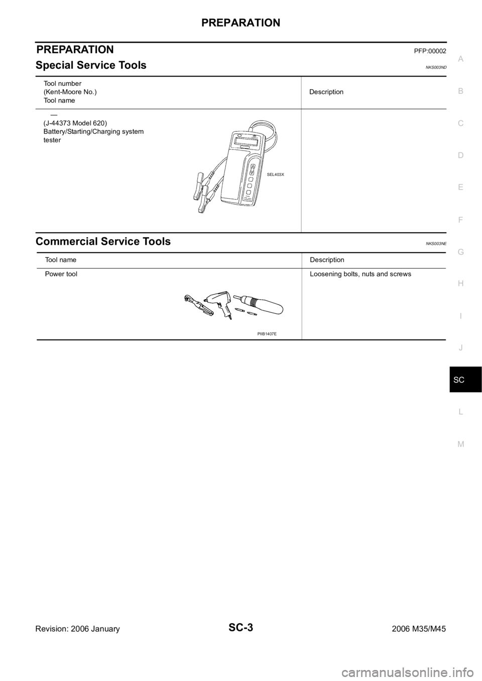
Battery/Starting/Charging system
tester
SEL403X
Tool nameDescription
Power toolLoosening bolts, nuts and screws
PIIB1407E
Page 5141 of 5621
SC-4
BATTERY
Revision: 2006 January2006 M35/M45
BATTERY PFP:00011
How to Handle Battery NKS003NF
CAUTION:
If it becomes necessary to start the engine with a booster battery and jumper cables, use a 12-volt
booster battery.
After connecting battery cables, ensure that they are tightly clamped to battery terminals for good
contact.
Never add distilled water through the hole used to check specific gravity.
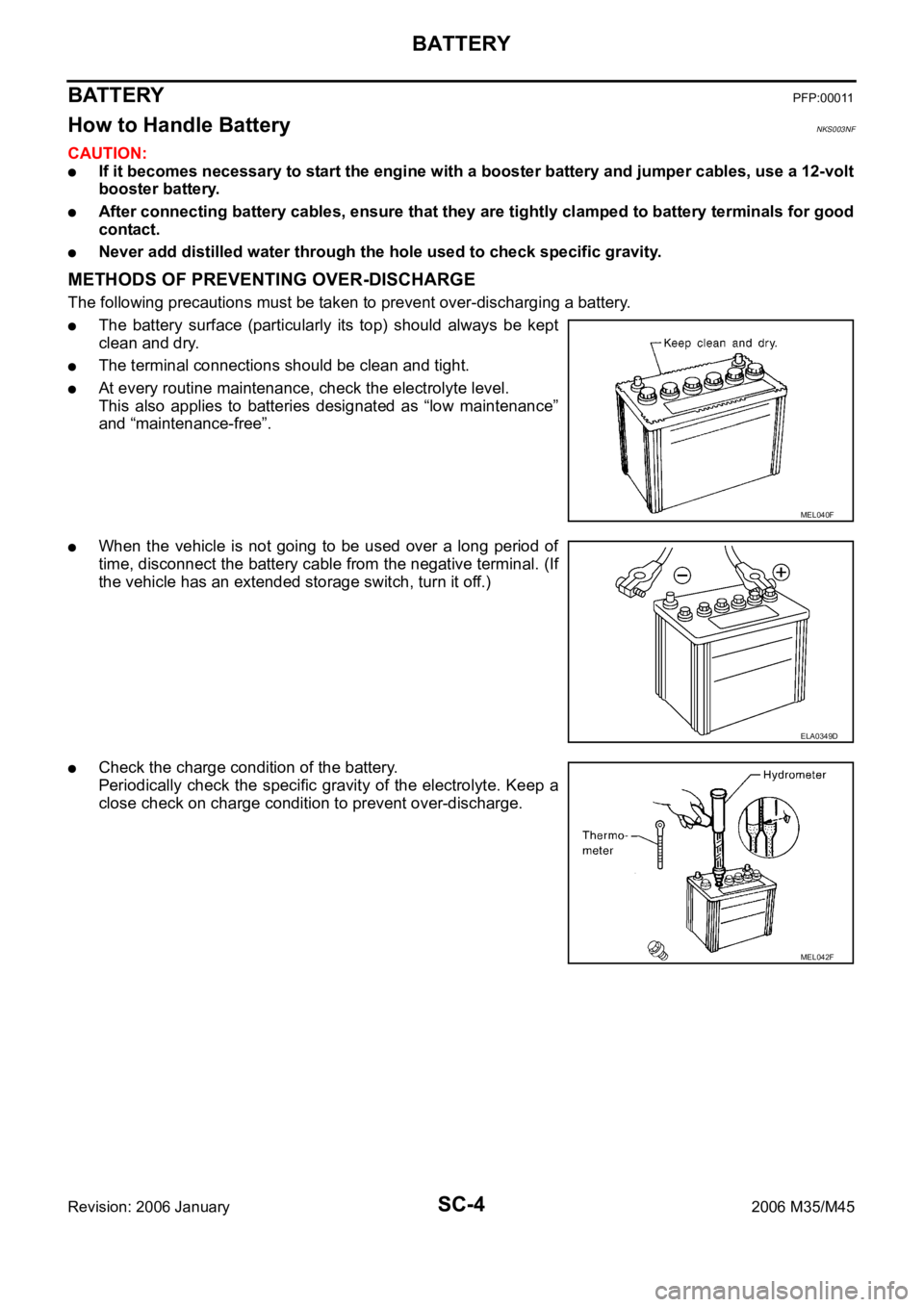
METHODS OF PREVENTING OVER-DISCHARGE
The following precautions must be taken to prevent over-discharging a battery.
The battery surface (particularly its top) should always be kept
clean and dry.
The terminal connections should be clean and tight.
At every routine maintenance, check the electrolyte level.
This also applies to batteries designated as “low maintenance”
and “maintenance-free”.
When the vehicle is not going to be used over a long period of
time, disconnect the battery cable from the negative terminal. (If
the vehicle has an extended storage switch, turn it off.)
Check the charge condition of the battery.
Periodically check the specific gravity of the electrolyte. Keep a
close check on charge condition to prevent over-discharge.
MEL040F
ELA0349D
MEL042F