Page 5162 of 5621
CHARGING SYSTEM
SC-25
C
D
E
F
G
H
I
J
L
MA
B
SC
Revision: 2006 January2006 M35/M45
Wiring Diagram — CHARGE — NKS003NO
VQ35DE ENGINE MODELS (2WD)
TKWT3234E
Page 5163 of 5621
SC-26
CHARGING SYSTEM
Revision: 2006 January2006 M35/M45
VQ35DE ENGINE MODELS (AWD)
TKWT3235E
Page 5164 of 5621
CHARGING SYSTEM
SC-27
C
D
E
F
G
H
I
J
L
MA
B
SC
Revision: 2006 January2006 M35/M45
VK45DE ENGINE MODELS
TKWT3236E
Page 5165 of 5621

SC-28
CHARGING SYSTEM
Revision: 2006 January2006 M35/M45
Trouble Diagnoses with Battery/Starting/Charging System Tester (Charging)NKS003NP
NOTE:
To ensure a complete and thorough diagnosis, the battery, starter and alternator test segments must be done
as a set from start to finish.
Before starting, perform the preliminary inspection. Refer to SC-32, "
PRELIMINARY INSPECTION" .
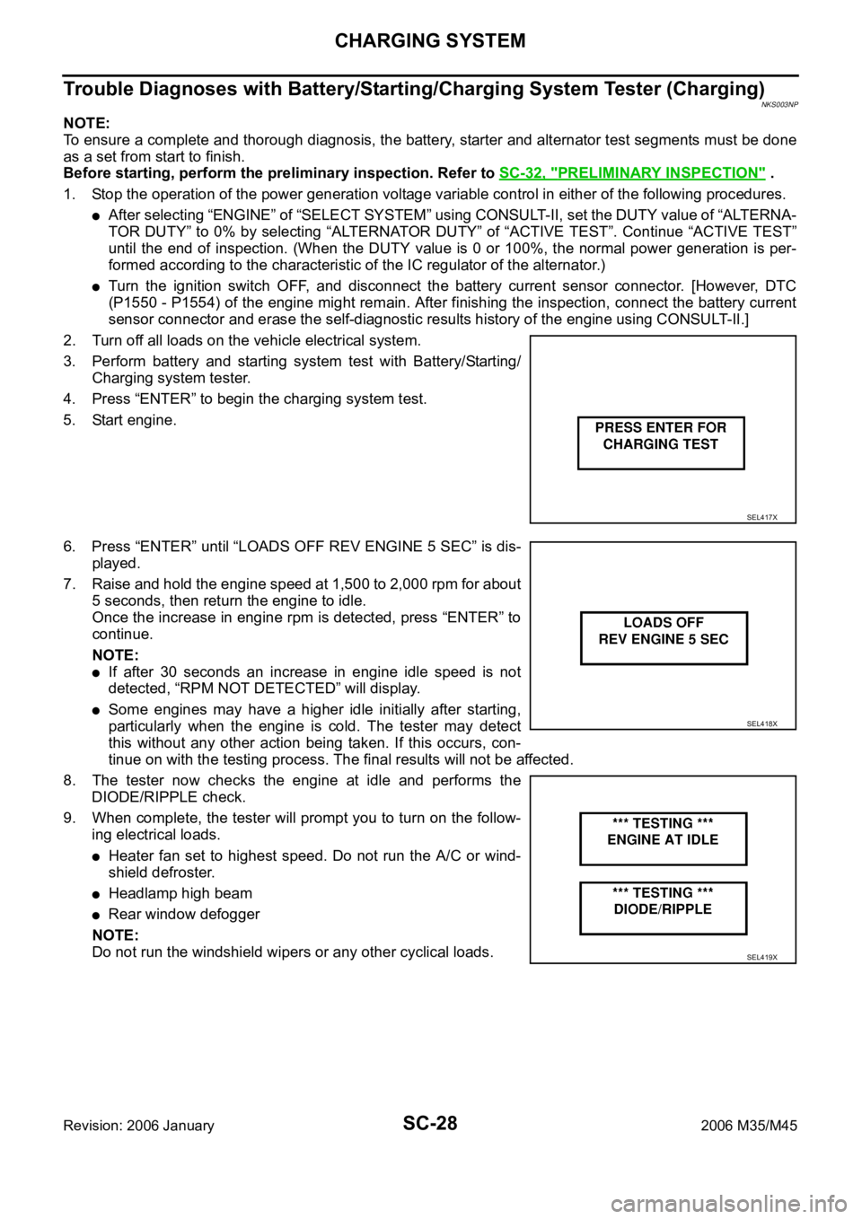
1. Stop the operation of the power generation voltage variable control in either of the following procedures.
After selecting “ENGINE” of “SELECT SYSTEM” using CONSULT-II, set the DUTY value of “ALTERNA-
TOR DUTY” to 0% by selecting “ALTERNATOR DUTY” of “ACTIVE TEST”. Continue “ACTIVE TEST”
until the end of inspection. (When the DUTY value is 0 or 100%, the normal power generation is per-
formed according to the characteristic of the IC regulator of the alternator.)
Turn the ignition switch OFF, and disconnect the battery current sensor connector. [However, DTC
(P1550 - P1554) of the engine might remain. After finishing the inspection, connect the battery current
sensor connector and erase the self-diagnostic results history of the engine using CONSULT-II.]
2. Turn off all loads on the vehicle electrical system.
3. Perform battery and starting system test with Battery/Starting/
Charging system tester.
4. Press “ENTER” to begin the charging system test.
5. Start engine.
6. Press “ENTER” until “LOADS OFF REV ENGINE 5 SEC” is dis-
played.
7. Raise and hold the engine speed at 1,500 to 2,000 rpm for about
5 seconds, then return the engine to idle.
Once the increase in engine rpm is detected, press “ENTER” to
continue.
NOTE:
If after 30 seconds an increase in engine idle speed is not
detected, “RPM NOT DETECTED” will display.
Some engines may have a higher idle initially after starting,
particularly when the engine is cold. The tester may detect
this without any other action being taken. If this occurs, con-
tinue on with the testing process. The final results will not be affected.
8. The tester now checks the engine at idle and performs the
DIODE/RIPPLE check.
9. When complete, the tester will prompt you to turn on the follow-
ing electrical loads.
Heater fan set to highest speed. Do not run the A/C or wind-
shield defroster.
Headlamp high beam
Rear window defogger
NOTE:
Do not run the windshield wipers or any other cyclical loads.
SEL417X
SEL418X
SEL419X
Page 5166 of 5621
CHARGING SYSTEM
SC-29
C
D
E
F
G
H
I
J
L
MA
B
SC
Revision: 2006 January2006 M35/M45
10. Press “ENTER” to continue.
11. Raise and hold the engine speed at 1,500 to 2,000 rpm for about
5 seconds, then return the engine to idle. Once the increase in
engine rpm is detected, press “ENTER” to continue.
NOTE:
If after 30 seconds an increase in engine idle speed is not
detected, “RPM NOT DETECTED” will be displayed. Press
“ENTER” to restart the test.
12. Diagnostic result is displayed on the tester. Refer to SC-30,
"DIAGNOSTIC RESULT ITEM CHART" .
13. Press “ENTER” then test output code is displayed. Record the
test output code on the repair order.
14. Toggle back to the “DIAGNOSTIC SCREEN” for test results.
SEL420X
SEL421X
SEL422X
SEL577X
Page 5167 of 5621
SC-30
CHARGING SYSTEM
Revision: 2006 January2006 M35/M45
DIAGNOSTIC RESULT ITEM CHART
Diagnostic item Service procedure
CHARGING SYSTEM NORMAL Charging system is normal and will also show “DIODE RIPPLE” test result.
NO CHARGING VOLTAGE
Go to SC-31, "
WORK FLOW" . LOW CHARGING VOLTAGE
HIGH CHARGING VOLTAGE
DIODE RIPPLE NORMAL Diode ripple is OK and will also show “CHARGING VOLTAGE” test result.
EXCESS RIPPLE DETECTEDReplace the alternator. Perform “DIODE RIPPLE” test again using Battery/Starting/Charging
system tester to confirm repair.
DIODE RIPPLE NOT DETECTED Go to SC-31, "
WORK FLOW" .
Page 5168 of 5621
CHARGING SYSTEM
SC-31
C
D
E
F
G
H
I
J
L
MA
B
SC
Revision: 2006 January2006 M35/M45
WORK FLOW
*1SC-32, "Check “L” Terminal Circuit
(Open)"
*2SC-33, "Check “L” Terminal Circuit
(Short)"
*3SC-33, "Check “S” Terminal Circuit"
*4SC-34, "Check “B” Terminal Circuit"*5SC-38, "Alternator Pulley Inspec-
tion" (VQ35DE)
SC-40, "
Alternator Pulley Inspec-
tion" (VK45DE)
SKIB0527E
Page 5169 of 5621

SC-32
CHARGING SYSTEM
Revision: 2006 January2006 M35/M45
PRELIMINARY INSPECTION
1. CHECK BATTERY TERMINALS CONNECTION
Check if battery terminals are clean and tight.
OK or NG
OK >> GO TO 2.
NG >> Repair battery terminals connection.
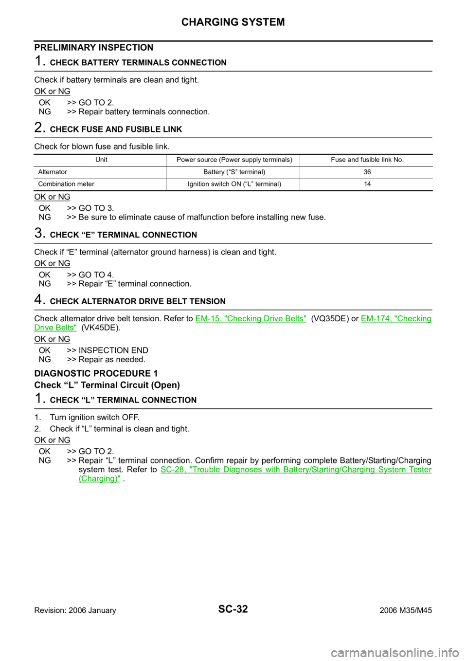
2. CHECK FUSE AND FUSIBLE LINK
Check for blown fuse and fusible link.
OK or NG
OK >> GO TO 3.
NG >> Be sure to eliminate cause of malfunction before installing new fuse.
3. CHECK “E” TERMINAL CONNECTION
Check if “E” terminal (alternator ground harness) is clean and tight.
OK or NG
OK >> GO TO 4.
NG >> Repair “E” terminal connection.
4. CHECK ALTERNATOR DRIVE BELT TENSION
Check alternator drive belt tension. Refer to EM-15, "
Checking Drive Belts" (VQ35DE) or EM-174, "Checking
Drive Belts" (VK45DE).
OK or NG
OK >> INSPECTION END
NG >> Repair as needed.
DIAGNOSTIC PROCEDURE 1
Check “L” Terminal Circuit (Open)
1. CHECK “L” TERMINAL CONNECTION
1. Turn ignition switch OFF.
2. Check if “L” terminal is clean and tight.
OK or NG
OK >> GO TO 2.
NG >> Repair “L” terminal connection. Confirm repair by performing complete Battery/Starting/Charging
system test. Refer to SC-28, "
Trouble Diagnoses with Battery/Starting/Charging System Tester
(Charging)" .
Unit Power source (Power supply terminals) Fuse and fusible link No.
Alternator Battery (“S” terminal) 36
Combination meter Ignition switch ON (“L” terminal) 14