2006 INFINITI M35 air condition
[x] Cancel search: air conditionPage 5319 of 5621

SE-138
CLIMATE CONTROLLED SEAT
Revision: 2006 January2006 M35/M45
2. CHECK SEAT CUSHION THERMAL ELECTRIC DEVICE SENSOR HARNESS
1. Turn ignition switch OFF.
2. Disconnect climate controlled seat control unit connector and seat cushion thermal electric device con-
nector.
3. Check continuity between climate controlled seat control unit
connector and seat cushion thermal electric device connector.
4. Check continuity between climate controlled seat control unit connector and ground.
OK or NG
OK >> GO TO 3.
NG >> Repair or replace harness between climate controlled seat control unit and seat cushion thermal
electric device.
3. CHECK SEAT CUSHION THERMAL ELECTRIC DEVICE SENSOR
Check resistance between seat cushion thermal electric device con-
nector.
OK or NG
OK >> Check the condition of the harness and the connector.
NG >> Replace seat cushion thermal electric device.
AB
Continuity Climate
controlled seat
control unit
connectorTe r m i n a lSeat cushion
thermal electric
device connectorTerminal
B283
(driver side)
B293
(passenger side)21 B285
(driver side)
B295
(passenger side)2
Ye s
22 1
A
GroundContinuity
Climate controlled seat
control unit connectorTerminal
B283 (driver side)
B293 (passenger side)21
No
22
PIIB6085E
Seat cushion thermal
electric device connectorTerminal Resistance (K)
(Approx.)
B220
(driver side)
B258
(passenger side)12 2
PIIB6086E
Page 5320 of 5621

CLIMATE CONTROLLED SEAT
SE-139
C
D
E
F
G
H
J
K
L
MA
B
SE
Revision: 2006 January2006 M35/M45
Seatback Thermal Electric Device Sensor Circuit InspectionNIS0027X
1. CHECK CLIMATE CONTROLLED SEAT CONTROL UNIT CIRCUIT
1. Turn ignition switch ON.
2. Check voltage between climate controlled seat control unit con-
nector and ground.
OK or NG
OK >> Climate controlled seat control unit circuit is OK.
NG >> GO TO 2.
2. CHECK SEATBACK THERMAL ELECTRIC DEVICE SENSOR HARNESS
1. Turn ignition switch OFF.
2. Disconnect climate controlled seat control unit connector and seatback thermal electric device connector.
3. Check continuity between climate controlled seat control unit
connector and seatback thermal electric device connector.
4. Check continuity between climate controlled seat control unit connector and ground.
OK or NG
OK >> GO TO 3.
NG >> Repair or replace harness between climate seat control unit and seatback thermal electric device.
Terminal
ConditionVoltage (V)
(Approx.) (+)
(–) Climate
controlled seat
control unit
connectorTe r m i n a l
B283
(driver side)
B293
(passenger side)23 GroundBlower motor
operated0.5 - 4
PIIB6087E
AB
Continuity Climate
controlled seat
control unit
connectorTerminalSeatback thermal
electric device
connectorTerminal
B283
(driver side)
B293
(passenger side)23 B220
(driver side)
B258
(passenger side)1
Ye s
24 2
A
GroundContinuity
Climate controlled seat
control unit connectorTerminal
B283 (driver side)
B293 (passenger side)23
No
24
PIIB6088E
Page 5321 of 5621

SE-140
CLIMATE CONTROLLED SEAT
Revision: 2006 January2006 M35/M45
3. CHECK SEATBACK THERMAL ELECTRIC DEVICE SENSOR
Check resistance between seatback thermal electric device connec-
tor.
OK or NG
OK >> Check the condition of the harness and the connector.
NG >> Replace seatback thermal electric device.
Climate Controlled Seat Blower Motor Circuit InspectionNIS0027Y
1. CHECK CLIMATE CONTROLLED SEAT BLOWER MOTOR CIRCUIT HARNESS
1. Turn ignition switch OFF.
2. Disconnect climate controlled seat control unit and climate controlled seat blower motor connector.
3. Check continuity between climate controlled seat control unit
connector and climate controlled seat blower motor connector.
4. Check continuity between climate controlled seat control unit connector and ground.
OK or NG
OK >> GO TO 2.
NG >> Repair or replace harness between climate controlled seat control unit and climate controlled seat
blower motor.
Seatback thermal electric
device connectorTe r m i n a l Resistance
(K)
(Approx.)
B220
(driver side)
B258
(passenger side)12 2
PIIB6086E
AB
Continuity Climate
controlled seat
control unit
connectorTe r m i n a lClimate controlled
seat blower motor
connectorTerminal
B283
(driver side)
B293
(passenger side)7
B282
(driver side)
B292
(passenger side)3
Ye s 14 2
17 4
18 1
A
GroundContinuity
Climate controlled seat
control unit connectorTerminal
B283
(driver side)
B293
(passenger side)7
No 14
17
18
PIIB6089E
Page 5332 of 5621
HEATED SEAT
SE-151
C
D
E
F
G
H
J
K
L
MA
B
SE
Revision: 2006 January2006 M35/M45
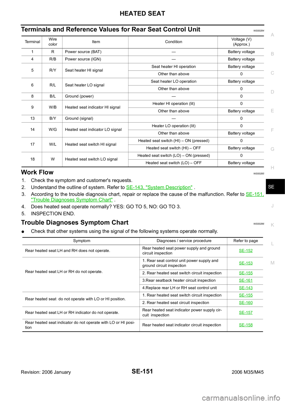
Terminals and Reference Values for Rear Seat Control UnitNIS00284
Work FlowNIS00285
1. Check the symptom and customer's requests.
2. Understand the outline of system. Refer to SE-143, "
System Description" .
3. According to the trouble diagnosis chart, repair or replace the cause of the malfunction. Refer to SE-151,
"Trouble Diagnoses Symptom Chart" .
4. Does heated seat operate normally? YES: GO TO 5, NO: GO TO 3.
5. INSPECTION END.
Trouble Diagnoses Symptom ChartNIS00286
Check that other systems using the signal of the following systems operate normally.
Te r m i n a lWire
colorItem ConditionVoltage (V)
(Approx.)
1 R Power source (BAT) — Battery voltage
4 R/B Power source (IGN) — Battery voltage
5 R/Y Seat heater HI signalSeat heater HI operation Battery voltage
Other than above 0
6 R/L Seat heater LO signalSeat heater LO operation Battery voltage
Other than above 0
8 B/L Ground (power) — 0
9 W/B Heated seat indicator HI signalHeater HI operation (lit) 0
Other than above Battery voltage
13 B/Y Ground (signal) — 0
14 W/G Heated seat indicator LO signalHeater LO operation (lit) 0
Other than above Battery voltage
17 W/L Heated seat switch HI signalHeated seat switch (HI) – ON (pressed) 0
Heated seat switch (HI) – OFF Battery voltage
18 W Heated seat switch LO signalHeated seat switch (LO) – ON (pressed) 0
Heated seat switch (LO) – OFF Battery voltage
Symptom Diagnoses / service procedure Refer to page
Rear heated seat LH and RH does not operate.Rear heated seat power supply and ground
circuit inspectionSE-152
Rear heated seat LH or RH do not operate.1. Rear seat control unit power supply and
ground circuit inspectionSE-1532. Rear heated seat switch circuit inspectionSE-155
3.Rear seatback heater circuit inspectionSE-161
4.Replace rear LH or RH seat control unitSE-143
Rear heated seat do not operate with LO or HI position.1. Rear heated seat switch circuit inspectionSE-1552. Rear heated seat circuit inspectionSE-160
Rear heated seat LH or RH indicator do not operate.Rear heated seat indicator power supply cir-
cuit inspectionSE-157
Rear heated seat indicator do not operate with LO or HI posi-
tionRear heated seat indicator circuit inspectionSE-158
Page 5333 of 5621

SE-152
HEATED SEAT
Revision: 2006 January2006 M35/M45
Rear Heated Seat Power Supply and Ground Circuit InspectionNIS00287
1. CHECK FUSIBLE LINK AND FUSE
Check 50A fusible link (letter F located in the fuse and fusible link box).
Check 15A fuse (No.38, located in fuse block).
Check circuit breaker.
NOTE:
Refer to SE-143, "
Component Parts and Harness Connector Location" .
OK or NG
OK >> GO TO 2.
NG >> If fuse or circuit breaker is blown, be sure to eliminate cause of malfunction before installing new
fuse or new circuit breaker, refer to PG-3, "
POWER SUPPLY ROUTING CIRCUIT" .
2. CHECK HEATED SEAT RELAY POWER SUPPLY CIRCUIT
1. Turn ignition switch OFF.
2. Check voltage between IPDM E/R (heated seat relay) connector
and ground.
OK or NG
OK >> GO TO 3.
NG >> Repair or replace harness between fuse block (J/B) and IPDM E/R (heated seat relay).
3. CHECK HEATED SEAT RELAY GROUND CIRCUIT
1. Disconnect IPDM E/R (heated seat relay) connector.
2. Check continuity between IPDM E/R (heated seat relay) con-
nector and ground.
OK or NG
OK >> Check the condition of the harness and connector.
NG >> Repair or replace harness between IPDM E/R (heated
seat relay) and ground.
Terminal
Voltage (V)
(Approx.) (+)
(–) IPDM E/R
(heated seat relay)
connectorTerminal
E6 14 Ground Battery voltage
PIIB5995E
Te r m i n a l
Continuity IPDM E/R
(heated seat relay)
connectorTerminal
Ground
E9 54 Yes
PIIB5996E
Page 5362 of 5621

H RESTRAINTS
CONTENTS
C
D
E
F
G
I
J
K
L
M
SECTION SRS
A
B
SRS
Revision: 2006 January2006 M35/M45
SUPPLEMENTAL RESTRAINT SYSTEM (SRS)
PRECAUTIONS ...........")
SRS-1
SUPPLEMENTAL RESTRAINT SYSTEM (SRS)
H RESTRAINTS
CONTENTS
C
D
E
F
G
I
J
K
L
M
SECTION SRS
A
B
SRS
Revision: 2006 January2006 M35/M45
SUPPLEMENTAL RESTRAINT SYSTEM (SRS)
PRECAUTIONS .......................................................... 3
Precautions for Supplemental Restraint System
(SRS) “AIR BAG” and “SEAT BELT PRE-TEN-
SIONER” .................................................................. 3
Precautions for SRS “AIR BAG” and “SEAT BELT
PRE-TENSIONER” Service ..................................... 3
Occupant Classification System Precaution ............ 3
PREPARATION ........................................................... 4
Commercial Service Tools ........................................ 4
SUPPLEMENTAL RESTRAINT SYSTEM (SRS) ....... 5
SRS Configuration ..............................................
..... 5
Front Seat Belt Pre-Tensioner with Load Limiter ...... 6
Front Side Air Bag .................................................... 6
Side Curtain Air Bag ................................................. 6
Occupant Classification System (OCS) ................... 7
Passenger Air Bag Status Condition ........................ 7
Component Parts of Occupant Classification Sys-
tem ........................................................................... 7
TROUBLE DIAGNOSIS .............................................. 8
Trouble Diagnosis Introduction ................................. 8
DIAGNOSIS FUNCTION ....................................... 8
HOW TO PERFORM TROUBLE DIAGNOSIS
FOR QUICK AND ACCURATE REPAIR ............... 8
WORK FLOW ........................................................ 9
Component Parts Location ..................................... 10
Schematic ............................................................... 11
Wiring Diagram — SRS — ..................................... 12
CONSULT-II Function ............................................ 17
DIAGNOSIS MODE FOR CONSULT-II ............... 17
HOW TO CHANGE SELF-DIAGNOSIS MODE
WITH CONSULT-II .............................................. 17
HOW TO ERASE SELF-DIAGNOSTIC
RESULTS ............................................................ 18
Self-Diagnosis Function (Without CONSULT-II) ..... 18
HOW TO CHANGE SELF-DIAGNOSIS MODE
WITHOUT CONSULT-II ...................................... 18
HOW TO ERASE SELF-DIAGNOSTIC
RESULTS ............................................................ 18
SRS Operation Check ............................................ 19
DIAGNOSTIC PROCEDURE 1 ........................... 19Trouble Diagnosis with CONSULT-II ...................... 21
DIAGNOSTIC PROCEDURE 2 ........................... 21
DIAGNOSTIC PROCEDURE 3 ........................... 25
DIAGNOSTIC PROCEDURE 4 (CONTINUED
FROM DIAGNOSTIC PROCEDURE 2) .............. 27
DIAGNOSTIC PROCEDURE 5 ........................... 27
Trouble Diagnosis without CONSULT-II ................. 32
DIAGNOSTIC PROCEDURE 6 ........................... 32
WARNING LAMP FLASH CODE CHART ........... 32
Trouble Diagnosis: “AIR BAG” Warning Lamp Does
Not Turn OFF ......................................................... 36
DIAGNOSTIC PROCEDURE 7 ........................... 36
Trouble Diagnosis: “AIR BAG” Warning Lamp Does
Not Turn ON ........................................................... 37
DIAGNOSTIC PROCEDURE 8 ........................... 37
DRIVER AIR BAG MODULE .................................... 38
Removal and Installation ........................................ 38
REMOVAL ........................................................
... 38
INSTALLATION ................................................... 39
SPIRAL CABLE ........................................................ 40
Removal and Installation ........................................ 40
REMOVAL ........................................................
... 40
INSTALLATION ................................................... 40
FRONT PASSENGER AIR BAG MODULE .............. 42
Removal and Installation ........................................ 42
REMOVAL ........................................................
... 42
INSTALLATION ................................................... 42
SIDE CURTAIN AIR BAG MODULE ........................ 43
Removal and Installation ........................................ 43
REMOVAL ........................................................
... 43
INSTALLATION ................................................... 44
CRASH ZONE SENSOR ........................................... 45
Removal and Installation ........................................ 45
REMOVAL ........................................................
... 45
INSTALLATION ................................................... 45
SIDE AIR BAG (SATELLITE) SENSOR ................... 46
Removal and Installation ........................................ 46
REMOVAL ........................................................
... 46
INSTALLATION ................................................... 46
Page 5368 of 5621

SRS-7
C
D
E
F
G
I
J
K
L
MA
B
SRS
Revision: 2006 January2006 M35/M45
Occupant Classification System (OCS) NHS0008W
The occupant classification system identifies diff")
SUPPLEMENTAL RESTRAINT SYSTEM (SRS)
SRS-7
C
D
E
F
G
I
J
K
L
MA
B
SRS
Revision: 2006 January2006 M35/M45
Occupant Classification System (OCS) NHS0008W
The occupant classification system identifies different size occupants, out of position occupants, and detects if
child seat is present in the front passenger seat. The occupant classification system receives inputs from the
occupant classification sensor (located inside the passenger seat cushion assembly) and belt tension sensor
(part of the passenger front seat belt assembly and located at the belt anchor location). Depending on classifi-
cation of passenger, the occupant classification system sends a signal to the diagnosis sensor unit. The diag-
nosis sensor unit uses this signal to determine full, partial, or non deployment of passenger front air bag in the
event of a collision. Depending on the signal received, the diagnosis sensor unit can disable the passenger
front air bag completely.
NOTE:
In case of customer concern, CONSULT-ll can be used to confirm the passenger air bag status (readiness).
Passenger Air Bag Status Condition NHS0008X
NOTE:
Passenger does not meet Ocuupant classification System specifications for passenger air bag activation.
Component Parts of Occupant Classification System NHS0008Y
Front Passenger Seat
(Condition)PASS AIR BAG OFF Indicator
(Status)Passenger Air Bag Status
(Readiness)CONSULT-ll Display
Seat occupied OFF Active (enabled) ON
seat occupiedNOTE ON Deactivated (disabled) OFF
Seat empty OFF Deactivated (disabled) OFF
PHIA1177E
1.Occupant classification system con-
trol unit2. Belt tension sensor 3. Seat pressure sensor
4. Bladder 5.Front passenger air bag OFF indica-
tor (Cutoff telltaile)
Page 5369 of 5621

SRS-8
TROUBLE DIAGNOSIS
Revision: 2006 January2006 M35/M45
TROUBLE DIAGNOSISPFP:00004
Trouble Diagnosis IntroductionNHS00090
CAUTION:
Do not use electrical test equipment on any circuit related to the SRS unless instructed in this Ser-
vice Manual. SRS wiring harnesses can be identified by yellow and/or orange harnesses or har-
ness connectors.
Do not repair, splice or modify the SRS wiring harness. If the harness is damaged, replace it with a
new one.
Keep ground portion clean.
DIAGNOSIS FUNCTION
The SRS self-diagnosis results can be read by using “AIR BAG” warning lamp and/or CONSULT-II.
The User mode is exclusively prepared for the customer (driver). This mode warns the driver of a system mal-
function through the operation of the “AIR BAG” warning lamp.
The Diagnosis mode allows the technician to locate and inspect the malfunctioning part.
The mode applications for the “AIR BAG” warning lamp and CONSULT-II are as follows:
HOW TO PERFORM TROUBLE DIAGNOSIS FOR QUICK AND ACCURATE REPAIR
A good understanding of the malfunction conditions can make troubleshooting faster and more accurate.
In general, each customer feels differently about a malfunction. It is important to fully understand the symp-
toms or conditions for a customer complaint.
Information from Customer
WHAT..... Vehicle model
WHEN..... Date, Frequencies
WHERE..... Road conditions
HOW..... Operating conditions, Symptoms
Preliminary Check
Make sure the following parts are in good order.
Battery (Refer to SC-4, "How to Handle Battery" .)
Fuse (Refer to SRS-12, "Wiring Diagram — SRS —" .)
System component-to-harness connections
User mode Diagnosis mode Display type
“AIR BAG” warning lamp X X ON-OFF operation
CONSULT-II — X Monitoring