2006 INFINITI M35 pressure
[x] Cancel search: pressurePage 4423 of 5621
![INFINITI M35 2006 Factory Service Manual LAN-754
[CAN]
CAN SYSTEM (TYPE 15)
Revision: 2006 January2006 M35/M45
11 . CHECK HARNESS FOR SHORT CIRCUIT
Check continuity between data link connector terminals and ground.
OK or NG
OK >> GO TO 12.
INFINITI M35 2006 Factory Service Manual LAN-754
[CAN]
CAN SYSTEM (TYPE 15)
Revision: 2006 January2006 M35/M45
11 . CHECK HARNESS FOR SHORT CIRCUIT
Check continuity between data link connector terminals and ground.
OK or NG
OK >> GO TO 12.](/manual-img/42/57023/w960_57023-4422.png)
LAN-754
[CAN]
CAN SYSTEM (TYPE 15)
Revision: 2006 January2006 M35/M45
11 . CHECK HARNESS FOR SHORT CIRCUIT
Check continuity between data link connector terminals and ground.
OK or NG
OK >> GO TO 12.
NG >> Check the following harnesses. If any harness is dam-
aged, repair the harness.
Harness between data link connector and harness
connector M62
Harness between data link connector and low tire pressure warning control unit
Harness between data link connector and steering angle sensor
Harness between data link connector and Intelligent Key unit
Harness between data link connector and unified meter and A/C amp.
Harness between data link connector and harness connector M53
Harness between data link connector and harness connector M13
12. CHECK HARNESS FOR SHORT CIRCUIT
1. Disconnect NAVI control unit connector.
2. Check continuity between NAVI control unit harness connector
terminals.
OK or NG
OK >> GO TO 13.
NG >> Repair harness between NAVI control unit and harness
connector M216.
13. CHECK HARNESS FOR SHORT CIRCUIT
Check continuity between NAVI control unit harness connector ter-
minals and ground.
OK or NG
OK >> GO TO 14.
NG >> Repair harness between NAVI control unit and harness
connector M216.
Data link
connectorTerminal
GroundContinuity
M606No
14 No
PKIA9872E
NAVI control unit
connectorTerminal Continuity
M210 71 72 No
PKIC0288E
NAVI control unit
connectorTerminal
GroundContinuity
M21071 No
72 No
PKIC0291E
Page 4427 of 5621
![INFINITI M35 2006 Factory Service Manual LAN-758
[CAN]
CAN SYSTEM (TYPE 15)
Revision: 2006 January2006 M35/M45
22. CHECK UNIT REPRODUCIBILITY
Performs the following procedure for each unit, and then perform reproducibility test.
1. Turn igni INFINITI M35 2006 Factory Service Manual LAN-758
[CAN]
CAN SYSTEM (TYPE 15)
Revision: 2006 January2006 M35/M45
22. CHECK UNIT REPRODUCIBILITY
Performs the following procedure for each unit, and then perform reproducibility test.
1. Turn igni](/manual-img/42/57023/w960_57023-4426.png)
LAN-758
[CAN]
CAN SYSTEM (TYPE 15)
Revision: 2006 January2006 M35/M45
22. CHECK UNIT REPRODUCIBILITY
Performs the following procedure for each unit, and then perform reproducibility test.
1. Turn ignition switch OFF.
2. Disconnect the battery cable from the negative terminal.
3. Disconnect the unit connector.
4. Connect the battery cable to the negative terminal.
5. Make sure that the symptom filled in the “Symptom” of the check sheet is reproduced. (Do not confuse it
with the symptom related to removed unit.)
6. Make sure that the same symptom is reproduced.
–A/T assembly
–AWD control unit
–AFS control unit
–BCM
–LDW camera unit
–Low tire pressure warning control unit
–Steering angle sensor
–Intelligent Key unit
–Unified meter and A/C amp.
–NAVI control unit
–Pre-crash seat belt control unit
–Driver seat control unit
–ABS actuator and electric unit (control unit)
–ICC sensor integrated unit
–ECM
–IPDM E/R
Check results
Reproduce>>Install removed unit, and then check the other unit.
Not reproduced>>Replace removed unit.
IPDM E/R Ignition Relay Circuit InspectionNKS00484
Check the following. If no malfunction is found, replace the IPDM E/R.
IPDM E/R power supply circuit. Refer to PG-30, "Check IPDM E/R Power Supply and Ground Circuit" .
Ignition power supply circuit. Refer to PG-12, "IGNITION POWER SUPPLY — IGNITION SW. IN “ON”
AND/OR “START”" .
Page 4465 of 5621

LT-38
HEADLAMP (FOR USA) - CONVENTIONAL TYPE -
Revision: 2006 January2006 M35/M45
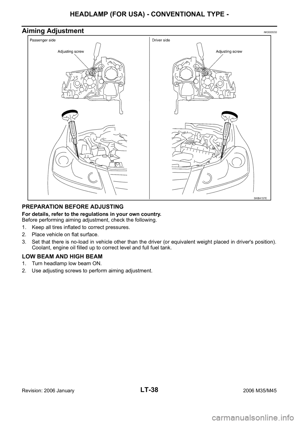
Aiming AdjustmentNKS003OG
PREPARATION BEFORE ADJUSTING
For details, refer to the regulations in your own country.
Before performing aiming adjustment, check the following.
1. Keep all tires inflated to correct pressures.
2. Place vehicle on flat surface.
3. Set that there is no-load in vehicle other than the driver (or equivalent weight placed in driver's position).
Coolant, engine oil filled up to correct level and full fuel tank.
LOW BEAM AND HIGH BEAM
1. Turn headlamp low beam ON.
2. Use adjusting screws to perform aiming adjustment.
SKIB4157E
Page 4501 of 5621

LT-74
HEADLAMP (FOR USA) - XENON TYPE -
Revision: 2006 January2006 M35/M45
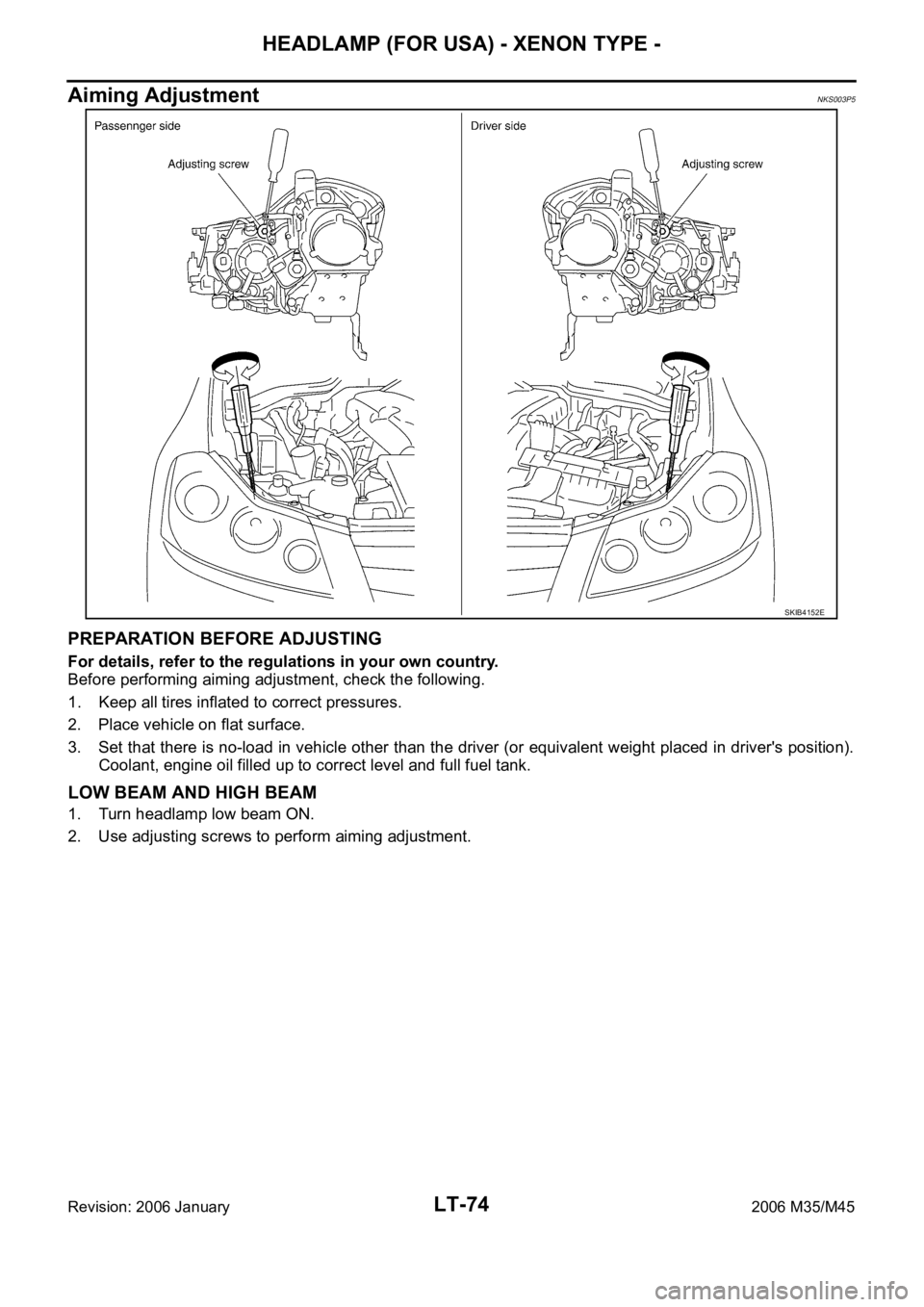
Aiming AdjustmentNKS003P5
PREPARATION BEFORE ADJUSTING
For details, refer to the regulations in your own country.
Before performing aiming adjustment, check the following.
1. Keep all tires inflated to correct pressures.
2. Place vehicle on flat surface.
3. Set that there is no-load in vehicle other than the driver (or equivalent weight placed in driver's position).
Coolant, engine oil filled up to correct level and full fuel tank.
LOW BEAM AND HIGH BEAM
1. Turn headlamp low beam ON.
2. Use adjusting screws to perform aiming adjustment.
SKIB4152E
Page 4636 of 5621

FRONT FOG LAMP
LT-209
C
D
E
F
G
H
I
J
L
MA
B
LT
Revision: 2006 January2006 M35/M45
3. CHECK CAN COMMUNICATIONS BETWEEN BCM AND IPDM E/R
Select “BCM” on CONSULT-II, and perform self-diagnosis for “BCM”.
Display of self-diagnosis results
NO DTC>> Replace IPDM E/R. Refer to PG-31, "Removal and
Installation of IPDM E/R" .
CAN COMM CIRCUIT>> Refer to BCS-15, "
CAN Communication
Inspection Using CONSULT-II (Self-Diagnosis)" .
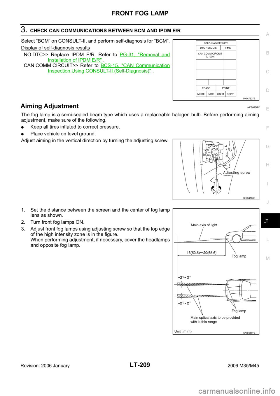
Aiming AdjustmentNKS003RH
The fog lamp is a semi-sealed beam type which uses a replaceable halogen bulb. Before performing aiming
adjustment, make sure of the following.
Keep all tires inflated to correct pressure.
Place vehicle on level ground.
Adjust aiming in the vertical direction by turning the adjusting screw.
1. Set the distance between the screen and the center of fog lamp
lens as shown.
2. Turn front fog lamps ON.
3. Adjust front fog lamps using adjusting screw so that the top edge
of the high intensity zone is in the figure.
When performing adjustment, if necessary, cover the headlamps
and opposite fog lamp.
PKIA7627E
SKIB4160E
SKIB0897E
Page 4744 of 5621

LU-1
ENGINE LUBRICATION SYSTEM
B ENGINE
CONTENTS
C
D
E
F
G
H
I
J
K
L
M
SECTION LU
A
LU
Revision: 2006 January2006 M35/M45
ENGINE LUBRICATION SYSTEM
VQ35DE
PRECAUTIONS .......................................................... 3
Precautions for Liquid Gasket .................................. 3
LIQUID GASKET APPLICATION PROCEDURE ..... 3
PREPARATION ........................................................... 4
Special Service Tools ............................................... 4
Commercial Service Tools ........................................ 4
LUBRICATION SYSTEM ............................................ 5
Lubrication Circuit .................................................... 5
System Chart ........................................................... 6
ENGINE OIL ............................................................... 7
Inspection ................................................................. 7
ENGINE OIL LEVEL ............................................. 7
ENGINE OIL APPEARANCE ................................ 7
ENGINE OIL LEAKAGE ........................................ 7
OIL PRESSURE CHECK ...................................... 8
Changing Engine Oil ................................................ 9
OIL FILTER ............................................................... 10
Removal and Installation ........................................ 10
REMOVAL ........................................................
... 10
INSTALLATION ................................................... 10
INSPECTION AFTER INSTALLATION ............... 10
OIL FILTER BRACKET (AWD) ................................. 12
Components ........................................................... 12
Removal and Installation ........................................ 12
REMOVAL ........................................................
... 12
INSTALLATION ................................................... 12
INSPECTION AFTER INSTALLATION ............... 13
OIL COOLER ............................................................ 14
Components ........................................................... 14
Removal and Installation ........................................ 15
REMOVAL ........................................................
... 15
INSPECTION AFTER REMOVAL ....................... 16
INSTALLATION ................................................... 16
INSPECTION AFTER INSTALLATION ............... 16
OIL PUMP ................................................................. 18
Components ........................................................... 18
Removal and Installation ........................................ 18
REMOVAL ........................................................
... 18
INSTALLATION ................................................... 18INSPECTION AFTER INSTALLATION ................ 18
Disassembly and Assembly .................................... 18
DISASSEMBLY ................................................... 18
INSPECTION AFTER DISASSEMBLY ................ 19
ASSEMBLY ......................................................... 20
SERVICE DATA AND SPECIFICATIONS (SDS) ...... 21
Standard and Limit .................................................. 21
ENGINE OIL PRESSURE ................................... 21
ENGINE OIL CAPACITY (APPROXIMATE) ........ 21
OIL PUMP ........................................................... 21
REGULATOR VALVE .......................................... 21
VK45DE
PRECAUTIONS ........................................................ 22
Precautions for Liquid Gasket ................................ 22
LIQUID GASKET APPLICATION PROCEDURE ... 22
PREPARATION ......................................................... 23
Special Service Tools ............................................. 23
Commercial Service Tools ...................................... 23
LUBRICATION SYSTEM .......................................... 24
Lubrication Circuit ................................................... 24
System Chart .......................................................... 25
ENGINE OIL .............................................................. 26
Inspection ............................................................... 26
ENGINE OIL LEVEL ............................................ 26
ENGINE OIL APPEARANCE .............................. 26
ENGINE OIL LEAKAGE ...................................... 26
OIL PRESSURE CHECK .................................... 26
Changing Engine Oil ............................................
... 28
OIL FILTER ............................................................... 29
Removal and Installation ........................................ 29
REMOVAL ........................................................
... 29
INSTALLATION ................................................... 29
INSPECTION AFTER INSTALLATION ................ 29
OIL PUMP ................................................................. 30
Components ........................................................... 30
Removal and Installation ........................................ 30
REMOVAL ........................................................
... 30
INSTALLATION ................................................... 30
Page 4745 of 5621

LU-2Revision: 2006 January2006 M35/M45 INSPECTION AFTER INSTALLATION ................ 31
Disassembly and Assembly .................................... 31
DISASSEMBLY ................................................... 31
INSPECTION AFTER DISASSEMBLY ................ 31
ASSEMBLY ......................................................... 32SERVICE DATA AND SPECIFICATIONS (SDS) ...... 33
Standard and Limit .................................................. 33
ENGINE OIL PRESSURE .................................... 33
ENGINE OIL CAPACITY (APPROXIMATE) ........ 33
OIL PUMP ............................................................ 33
REGULATOR VALVE ........................................... 33
Page 4747 of 5621
![INFINITI M35 2006 Factory Service Manual LU-4
[VQ35DE]
PREPARATION
Revision: 2006 January2006 M35/M45
PREPARATIONPFP:00002
Special Service ToolsNBS004PS
The actual shapes of Kent-Moore tools may differ from those of special service tools ill INFINITI M35 2006 Factory Service Manual LU-4
[VQ35DE]
PREPARATION
Revision: 2006 January2006 M35/M45
PREPARATIONPFP:00002
Special Service ToolsNBS004PS
The actual shapes of Kent-Moore tools may differ from those of special service tools ill](/manual-img/42/57023/w960_57023-4746.png)
LU-4
[VQ35DE]
PREPARATION
Revision: 2006 January2006 M35/M45
PREPARATIONPFP:00002
Special Service ToolsNBS004PS
The actual shapes of Kent-Moore tools may differ from those of special service tools illustrated here.
Commercial Service ToolsNBS004PT
Tool number
(Kent-Moore No.)
Tool nameDescription
ST25051001
(J25695-1)
Oil pressure gaugeMeasuring oil pressure
Maximum measuring range: 2.452 kPa (25
kg-cm
2 , 356 psi)
ST25052000
(J25695-2)
HoseAdapting oil pressure gauge to oil pan (upper)
KV10115801
(J38956)
Oil filter wrenchRemoving and installing oil filter
(2WD models)
a: 64.3 mm (2.531 in)
WS39930000
(—)
Tube presser Pressing tube of liquid gasket
NT050
S-NT559
S-NT375
NT052
Tool nameDescription
Power toolsLoosening nuts and bolts
Deep socketRemoving and installing oil pressure switch
a: 26 mm (1.02 in)
PBIC0190E
PBIC2072E