2006 INFINITI M35 turn signal
[x] Cancel search: turn signalPage 4459 of 5621
LT-32
HEADLAMP (FOR USA) - CONVENTIONAL TYPE -
Revision: 2006 January2006 M35/M45
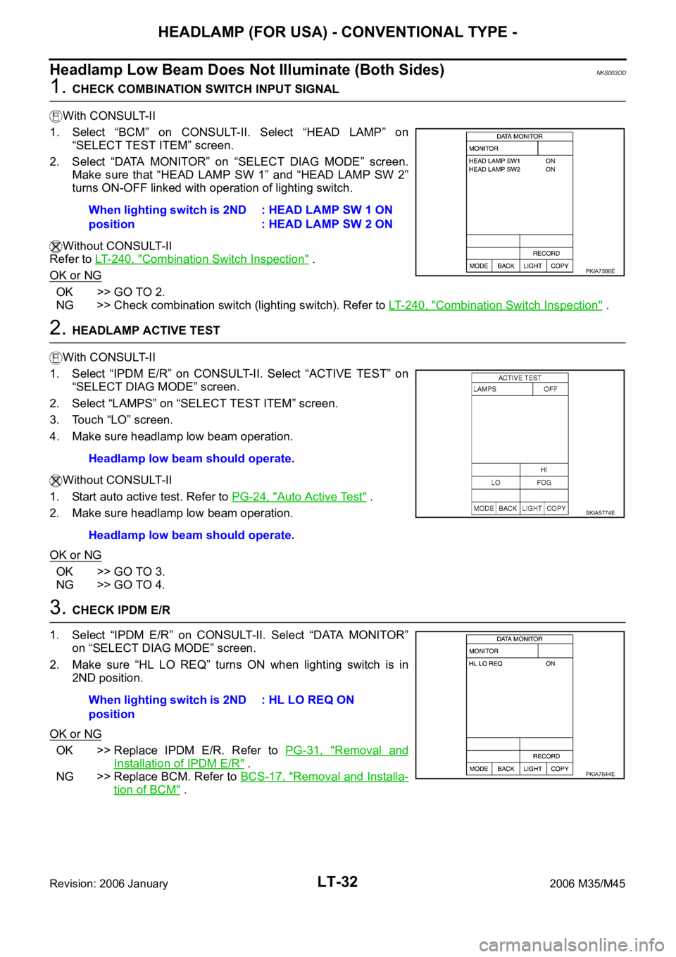
Headlamp Low Beam Does Not Illuminate (Both Sides)NKS003OD
1. CHECK COMBINATION SWITCH INPUT SIGNAL
With CONSULT-II
1. Select “BCM” on CONSULT-II. Select “HEAD LAMP” on
“SELECT TEST ITEM” screen.
2. Select “DATA MONITOR” on “SELECT DIAG MODE” screen.
Make sure that “HEAD LAMP SW 1” and “HEAD LAMP SW 2”
turns ON-OFF linked with operation of lighting switch.
Without CONSULT-II
Refer to LT- 2 4 0 , "
Combination Switch Inspection" .
OK or NG
OK >> GO TO 2.
NG >> Check combination switch (lighting switch). Refer to LT-240, "
Combination Switch Inspection" .
2. HEADLAMP ACTIVE TEST
With CONSULT-II
1. Select “IPDM E/R” on CONSULT-II. Select “ACTIVE TEST” on
“SELECT DIAG MODE” screen.
2. Select “LAMPS” on “SELECT TEST ITEM” screen.
3. Touch “LO” screen.
4. Make sure headlamp low beam operation.
Without CONSULT-II
1. Start auto active test. Refer to PG-24, "
Auto Active Test" .
2. Make sure headlamp low beam operation.
OK or NG
OK >> GO TO 3.
NG >> GO TO 4.
3. CHECK IPDM E/R
1. Select “IPDM E/R” on CONSULT-II. Select “DATA MONITOR”
on “SELECT DIAG MODE” screen.
2. Make sure “HL LO REQ” turns ON when lighting switch is in
2ND position.
OK or NG
OK >> Replace IPDM E/R. Refer to PG-31, "Removal and
Installation of IPDM E/R" .
NG >> Replace BCM. Refer to BCS-17, "
Removal and Installa-
tion of BCM" . When lighting switch is 2ND
position: HEAD LAMP SW 1 ON
: HEAD LAMP SW 2 ON
PKIA7586E
Headlamp low beam should operate.
Headlamp low beam should operate.
SKIA5774E
When lighting switch is 2ND
position: HL LO REQ ON
PKIA7644E
Page 4460 of 5621
HEADLAMP (FOR USA) - CONVENTIONAL TYPE -
LT-33
C
D
E
F
G
H
I
J
L
MA
B
LT
Revision: 2006 January2006 M35/M45
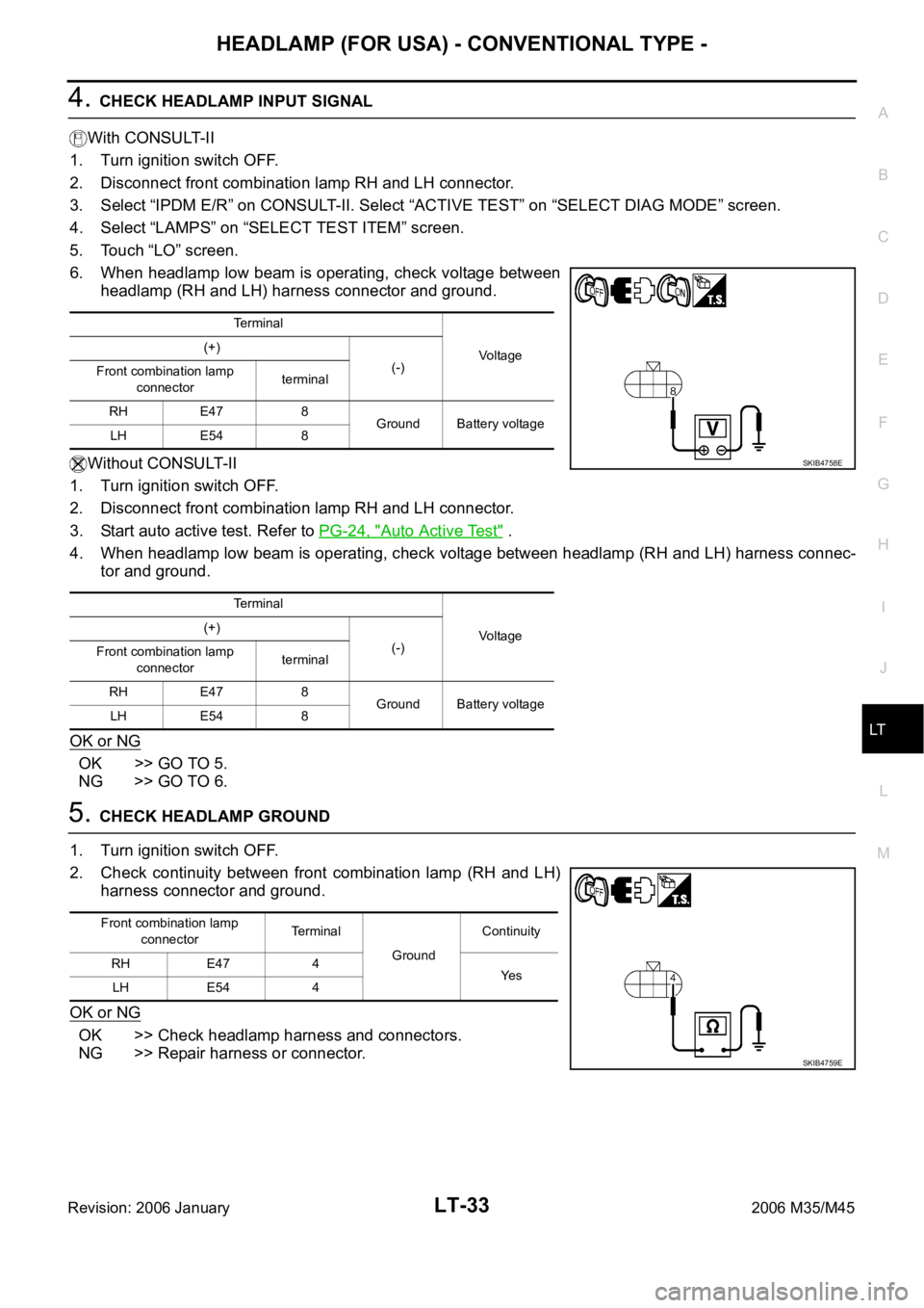
4. CHECK HEADLAMP INPUT SIGNAL
With CONSULT-II
1. Turn ignition switch OFF.
2. Disconnect front combination lamp RH and LH connector.
3. Select “IPDM E/R” on CONSULT-II. Select “ACTIVE TEST” on “SELECT DIAG MODE” screen.
4. Select “LAMPS” on “SELECT TEST ITEM” screen.
5. Touch “LO” screen.
6. When headlamp low beam is operating, check voltage between
headlamp (RH and LH) harness connector and ground.
Without CONSULT-II
1. Turn ignition switch OFF.
2. Disconnect front combination lamp RH and LH connector.
3. Start auto active test. Refer to PG-24, "
Auto Active Test" .
4. When headlamp low beam is operating, check voltage between headlamp (RH and LH) harness connec-
tor and ground.
OK or NG
OK >> GO TO 5.
NG >> GO TO 6.
5. CHECK HEADLAMP GROUND
1. Turn ignition switch OFF.
2. Check continuity between front combination lamp (RH and LH)
harness connector and ground.
OK or NG
OK >> Check headlamp harness and connectors.
NG >> Repair harness or connector.
Terminal
Voltage (+)
(-)
Front combination lamp
connectorterminal
RH E47 8
Ground Battery voltage
LH E54 8
Terminal
Voltage (+)
(-)
Front combination lamp
connectorterminal
RH E47 8
Ground Battery voltage
LH E54 8
SKIB4758E
Front combination lamp
connectorTe r m i n a l
GroundContinuity
RH E47 4
Ye s
LH E54 4
SKIB4759E
Page 4462 of 5621
HEADLAMP (FOR USA) - CONVENTIONAL TYPE -
LT-35
C
D
E
F
G
H
I
J
L
MA
B
LT
Revision: 2006 January2006 M35/M45
Headlamp Low Beam Does Not Illuminate (One Side)NKS003OE
1. CHECK BULB
Check bulb of lamp which does not illuminate.
OK or NG
OK >> GO TO 2.
NG >> Replace headlamp bulb.
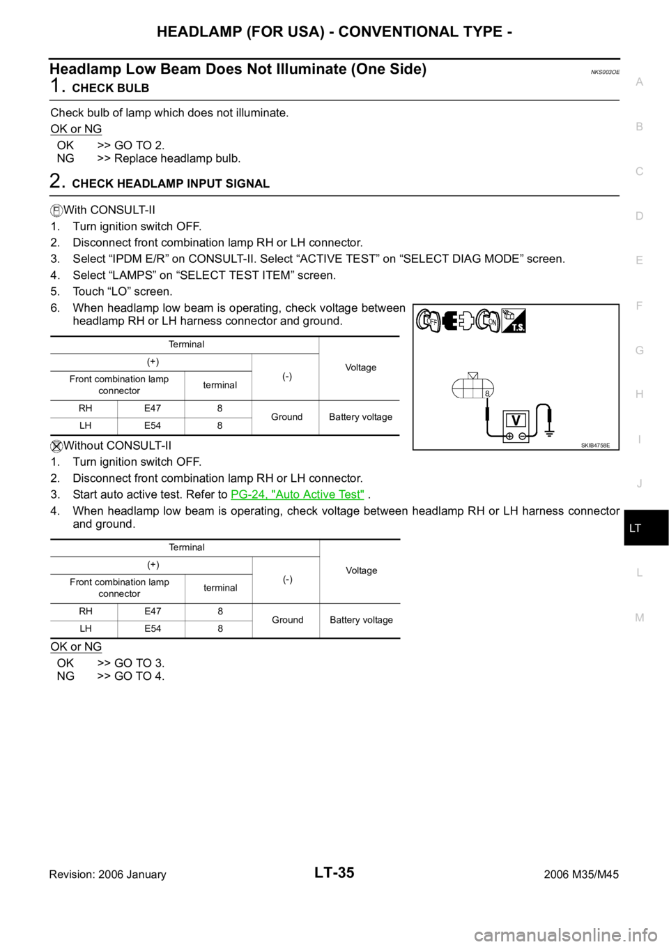
2. CHECK HEADLAMP INPUT SIGNAL
With CONSULT-II
1. Turn ignition switch OFF.
2. Disconnect front combination lamp RH or LH connector.
3. Select “IPDM E/R” on CONSULT-II. Select “ACTIVE TEST” on “SELECT DIAG MODE” screen.
4. Select “LAMPS” on “SELECT TEST ITEM” screen.
5. Touch “LO” screen.
6. When headlamp low beam is operating, check voltage between
headlamp RH or LH harness connector and ground.
Without CONSULT-II
1. Turn ignition switch OFF.
2. Disconnect front combination lamp RH or LH connector.
3. Start auto active test. Refer to PG-24, "
Auto Active Test" .
4. When headlamp low beam is operating, check voltage between headlamp RH or LH harness connector
and ground.
OK or NG
OK >> GO TO 3.
NG >> GO TO 4.
Te r m i n a l
Voltage (+)
(-)
Front combination lamp
connectorterminal
RH E47 8
Ground Battery voltage
LH E54 8
Terminal
Voltag e (+)
(-)
Front combination lamp
connectorterminal
RH E47 8
Ground Battery voltage
LH E54 8
SKIB4758E
Page 4464 of 5621
HEADLAMP (FOR USA) - CONVENTIONAL TYPE -
LT-37
C
D
E
F
G
H
I
J
L
MA
B
LT
Revision: 2006 January2006 M35/M45
Headlamps Do Not Turn OFFNKS003OF
1. CHECK HEADLAMP TURN OFF
Make sure that lighting switch is OFF. And make sure headlamp turns off when ignition switch is turned OFF.
OK or NG
OK >> GO TO 3.
NG >> GO TO 2.
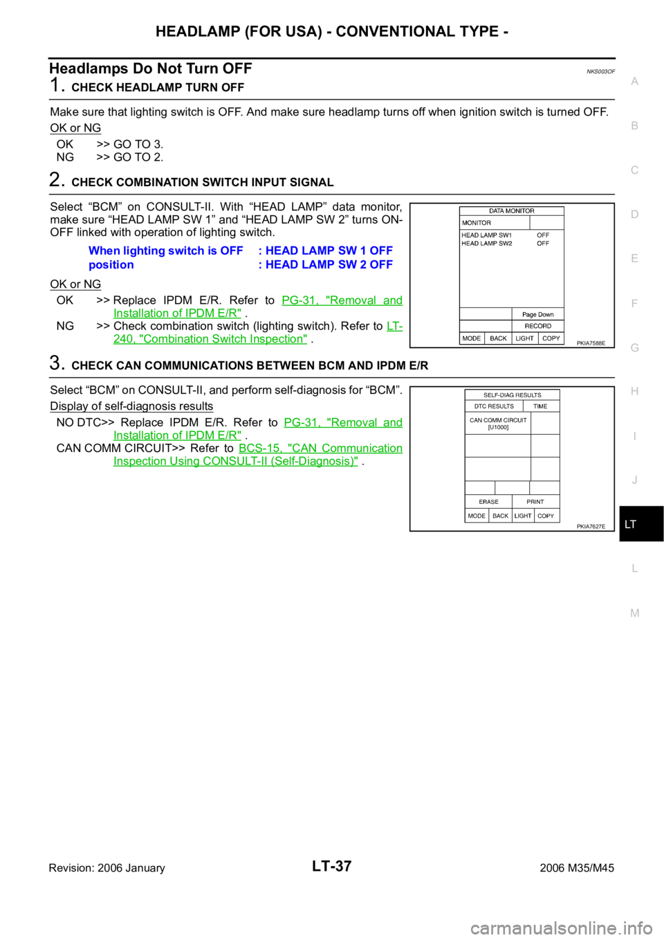
2. CHECK COMBINATION SWITCH INPUT SIGNAL
Select “BCM” on CONSULT-II. With “HEAD LAMP” data monitor,
make sure “HEAD LAMP SW 1” and “HEAD LAMP SW 2” turns ON-
OFF linked with operation of lighting switch.
OK or NG
OK >> Replace IPDM E/R. Refer to PG-31, "Removal and
Installation of IPDM E/R" .
NG >> Check combination switch (lighting switch). Refer to LT-
240, "Combination Switch Inspection" .
3. CHECK CAN COMMUNICATIONS BETWEEN BCM AND IPDM E/R
Select “BCM” on CONSULT-II, and perform self-diagnosis for “BCM”.
Display of self-diagnosis results
NO DTC>> Replace IPDM E/R. Refer to PG-31, "Removal and
Installation of IPDM E/R" .
CAN COMM CIRCUIT>> Refer to BCS-15, "
CAN Communication
Inspection Using CONSULT-II (Self-Diagnosis)" . When lighting switch is OFF
position: HEAD LAMP SW 1 OFF
: HEAD LAMP SW 2 OFF
PKIA7588E
PKIA7627E
Page 4467 of 5621
LT-40
HEADLAMP (FOR USA) - CONVENTIONAL TYPE -
Revision: 2006 January2006 M35/M45
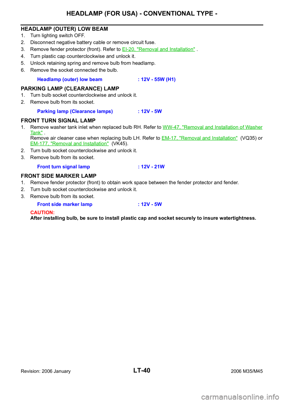
HEADLAMP (OUTER) LOW BEAM
1. Turn lighting switch OFF.
2. Disconnect negative battery cable or remove circuit fuse.
3. Remove fender protector (front). Refer to EI-20, "
Removal and Installation" .
4. Turn plastic cap counterclockwise and unlock it.
5. Unlock retaining spring and remove bulb from headlamp.
6. Remove the socket connected the bulb.
PARKING LAMP (CLEARANCE) LAMP
1. Turn bulb socket counterclockwise and unlock it.
2. Remove bulb from its socket.
FRONT TURN SIGNAL LAMP
1. Remove washer tank inlet when replaced bulb RH. Refer to WW-47, "Removal and Installation of Washer
Ta n k" .
Remove air cleaner case when replacing bulb LH. Refer to EM-17, "
Removal and Installation" (VQ35) or
EM-177, "
Removal and Installation" (VK45).
2. Turn bulb socket counterclockwise and unlock it.
3. Remove bulb from its socket.
FRONT SIDE MARKER LAMP
1. Remove fender protector (front) to obtain work space between the fender protector and fender.
2. Turn bulb socket counterclockwise and unlock it.
3. Remove bulb from its socket.
CAUTION:
After installing bulb, be sure to install plastic cap and socket securely to insure watertightness. Headlamp (outer) low beam : 12V - 55W (H1)
Parking lamp (Clearance lamps) : 12V - 5W
Front turn signal lamp : 12V - 21W
Front side marker lamp : 12V - 5W
Page 4469 of 5621

LT-42
HEADLAMP (FOR USA) - CONVENTIONAL TYPE -
Revision: 2006 January2006 M35/M45
Disassembly and AssemblyNKS003OJ
DISASSEMBLY
1. Turn plastic cap counterclockwise and unlock it.
2. Unlock retaining spring and remove halogen bulb (low).
3. Disconnect the socket connected to the bulb (low).
4. Turn bulb (high) counterclockwise and unlock it.
5. Remove bulb (high) and disconnect connector it.
6. Turn front turn signal lamp bulb socket counterclockwise and unlock it.
7. Remove front turn signal lamp bulb from its socket.
8. Turn parking lamp (Clearance lamp) bulb socket counterclockwise and unlock it.
9. Remove parking lamp (Clearance lamp) bulb from its socket.
10. Turn front side marker lamp bulb socket counterclockwise and unlock it.
11. Remove front side marker lamp bulb from its socket.
ASSEMBLY
Note the following, and installation is the reverse order of removal.
CAUTION:
After installing bulb, be sure to install plastic cap and bulb socket securely to insure watertightness.
1. Bulb socket (low) 2. Retaining spring 3. Bulb (low)
4. Seal packing 5. Plastic cap 6. Side marker lamp bulb socket
7. Side marker lamp bulb 8. Plastic cap 9. Seal packing
10. Bulb (high) 11. Front turn signal lamp bulb socket 12. Front turn signal lamp bulb
13. Headlamp housing assembly 14. Parking lamp (Clearance lamp) bulb 15. Parking lamp (Clearance lamp) bulb
socket
SKIB4158E
Page 4472 of 5621

HEADLAMP (FOR USA) - XENON TYPE -
LT-45
C
D
E
F
G
H
I
J
L
MA
B
LT
Revision: 2006 January2006 M35/M45
HEADLAMP OPERATION
Low Beam Operation
With the lighting switch in 2ND position, the BCM receives input signal requesting the headlamps to illuminate.
This input signal is communicated to the IPDM E/R across the CAN communication lines. The CPU located in
the IPDM E/R controls the headlamp low relay coil, which when energized, directs power
through 15A fuse (No. 76, located in IPDM E/R)
through IPDM E/R terminal 20
to front combination lamp RH terminal 8,
through 15A fuse (No. 86, located in IPDM E/R)
through IPDM E/R terminal 30
to front combination lamp LH terminal 8.
Ground is supplied
to front combination lamp RH terminal 4
to front combination lamp LH terminal 4
through grounds E22 and E43.
With power and ground supplied, low beam headlamps illuminate.
High Beam Operation/Flash-to-Pass Operation
With the lighting switch in 2ND position and placed in HIGH or PASS position, the BCM receives input signal
requesting the headlamp high beams and low beams to illuminate. This input signal is communicated to the
IPDM E/R across the CAN communication lines. The CPU located in the IPDM E/R controls the headlamp
high relay coil and low relay coil, which when energized, directs power
through 15A fuse (No. 76, located in IPDM E/R)
through IPDM E/R terminal 20
to front combination lamp RH terminal 8,
through 15A fuse (No. 86, located in IPDM E/R)
through IPDM E/R terminal 30
to front combination lamp LH terminal 8,
through 10A fuse (No. 72, located in IPDM E/R)
through IPDM E/R terminal 27
to front combination lamp RH terminal 6,
through 10A fuse (No. 74, located in IPDM E/R)
through IPDM E/R terminal 28
to front combination lamp LH terminal 6.
Ground is supplied
to front combination lamp RH terminal 4
to front combination lamp LH terminal 4
to front combination lamp RH terminal 2
to front combination lamp LH terminal 2
through grounds E22 and E43.
With power and ground supplied, the high beam and low beam headlamps illuminate.
The unified meter and A/C amp. that received the high beam request signal by BCM across the CAN commu-
nication makes a high beam indicator lamp turn on in the combination meter.
Page 4480 of 5621
HEADLAMP (FOR USA) - XENON TYPE -
LT-53
C
D
E
F
G
H
I
J
L
MA
B
LT
Revision: 2006 January2006 M35/M45
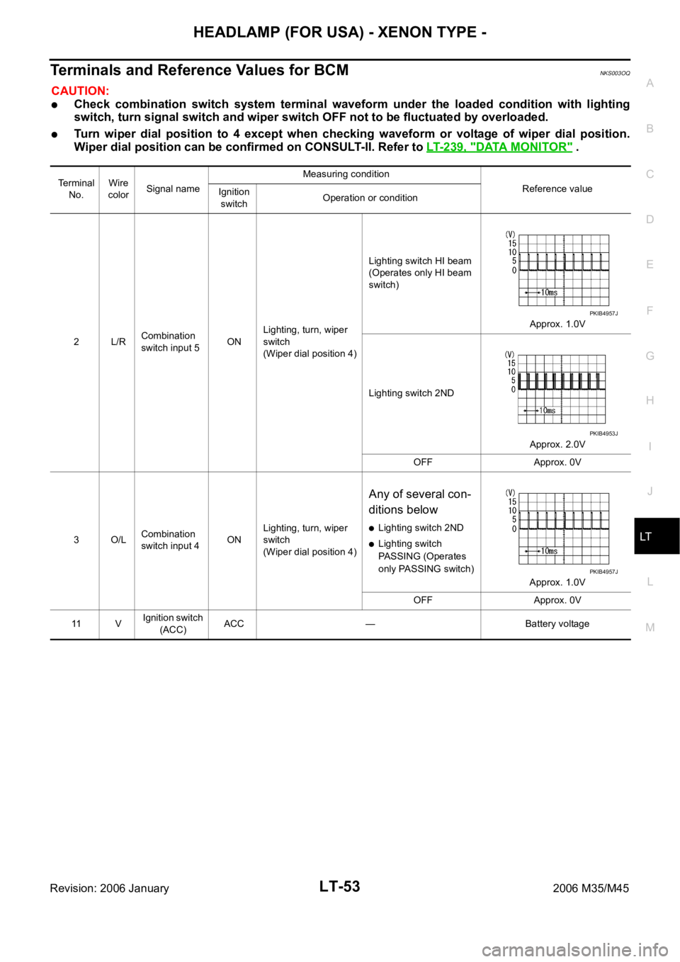
Terminals and Reference Values for BCMNKS003OQ
CAUTION:
Check combination switch system terminal waveform under the loaded condition with lighting
switch, turn signal switch and wiper switch OFF not to be fluctuated by overloaded.
Turn wiper dial position to 4 except when checking waveform or voltage of wiper dial position.
Wiper dial position can be confirmed on CONSULT-II. Refer to LT-239, "
DATA MONITOR" .
Terminal
No.Wire
colorSignal nameMeasuring condition
Reference value
Ignition
switchOperation or condition
2L/RCombination
switch input 5ONLighting, turn, wiper
switch
(Wiper dial position 4)Lighting switch HI beam
(Operates only HI beam
switch)
Approx. 1.0V
Lighting switch 2ND
Approx. 2.0V
OFF Approx. 0V
3O/LCombination
switch input 4ONLighting, turn, wiper
switch
(Wiper dial position 4)
Any of several con-
ditions below
Lighting switch 2ND
Lighting switch
PASSING (Operates
only PASSING switch)
Approx. 1.0V
OFF Approx. 0V
11 VIgnition switch
(ACC)ACC — Battery voltage
PKIB4957J
PKIB4953J
PKIB4957J