2006 INFINITI M35 light
[x] Cancel search: lightPage 4597 of 5621
LT-170
ACTIVE AFS
Revision: 2006 January2006 M35/M45
7. CHECK SWIVEL POSITION SENSOR GROUND CIRCUIT
1. Turn ignition switch OFF.
2. Disconnect AFS control unit connector and front combination lamp LH connector.
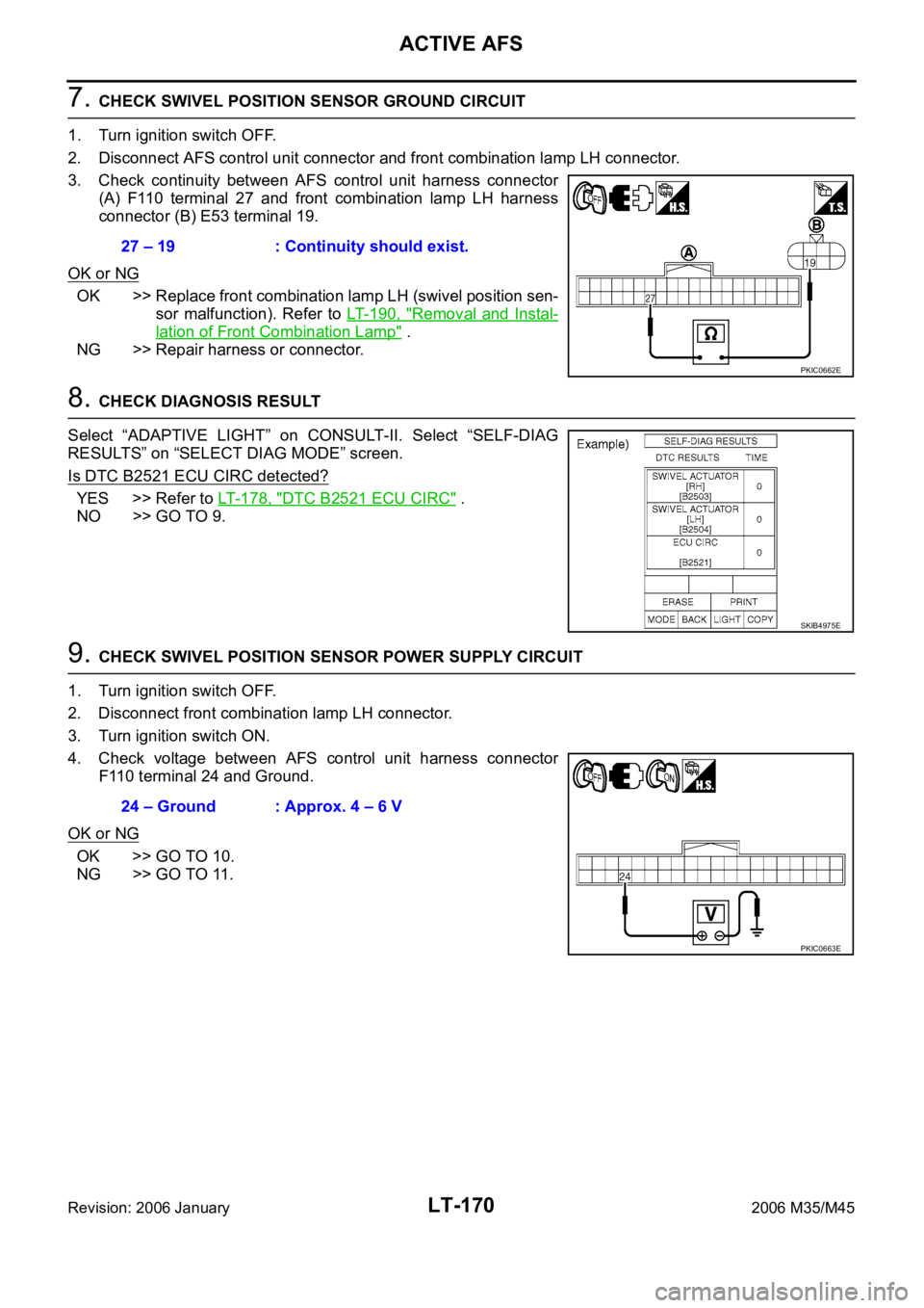
3. Check continuity between AFS control unit harness connector
(A) F110 terminal 27 and front combination lamp LH harness
connector (B) E53 terminal 19.
OK or NG
OK >> Replace front combination lamp LH (swivel position sen-
sor malfunction). Refer to LT- 1 9 0 , "
Removal and Instal-
lation of Front Combination Lamp" .
NG >> Repair harness or connector.
8. CHECK DIAGNOSIS RESULT
Select “ADAPTIVE LIGHT” on CONSULT-II. Select “SELF-DIAG
RESULTS” on “SELECT DIAG MODE” screen.
Is DTC B2521 ECU CIRC detected?
YES >> Refer to LT- 1 7 8 , "DTC B2521 ECU CIRC" .
NO >> GO TO 9.
9. CHECK SWIVEL POSITION SENSOR POWER SUPPLY CIRCUIT
1. Turn ignition switch OFF.
2. Disconnect front combination lamp LH connector.
3. Turn ignition switch ON.
4. Check voltage between AFS control unit harness connector
F110 terminal 24 and Ground.
OK or NG
OK >> GO TO 10.
NG >> GO TO 11.27 – 19 : Continuity should exist.
PKIC0662E
SKIB4975E
24 – Ground : Approx. 4 – 6 V
PKIC0663E
Page 4600 of 5621
ACTIVE AFS
LT-173
C
D
E
F
G
H
I
J
L
MA
B
LT
Revision: 2006 January2006 M35/M45
14. CHECK DIAGNOSIS RESULT 1
Select “ADAPTIVE LIGHT” on CONSULT-II. Select “SELF-DIAG
RESULTS” on “SELECT DIAG MODE” screen.
Is DTC of present malfunction detected?
YES >>If detect DTC B2503 and B2504, refer to LT- 1 6 8 ,
"DTC B2504 SWIVEL ACTUATOR LH" .
If detect DTC B2504 only, replace AFS control unit.
Refer to LT- 1 9 1 , "
Removal and Installation of AFS
Control Unit" .
If detect any DTC except B2503 and B2504, refer to
LT- 1 5 4 , "
SELF-DIAG RESULTS" .
NO >> GO TO 15.
15. CHECK DIAGNOSIS RESULT 2
Check “SELF-DIAG RESULTS” with steering turning 180
or more to
left under swivel operative condition to keep more than 2 seconds.
Is DTC B2504 of present malfunction detected?
YES >> Replace front combination lamp LH (swivel actuator
malfunction). Refer to LT- 1 9 0 , "
Removal and Installation
of Front Combination Lamp" .
NO >> The swivel actuator system LH is normal at present.
16. CHECK SWIVEL MOTOR CIRCUIT 2
1. Turn ignition switch OFF.
2. Disconnect AFS control unit connector and front combination lamp LH connector.
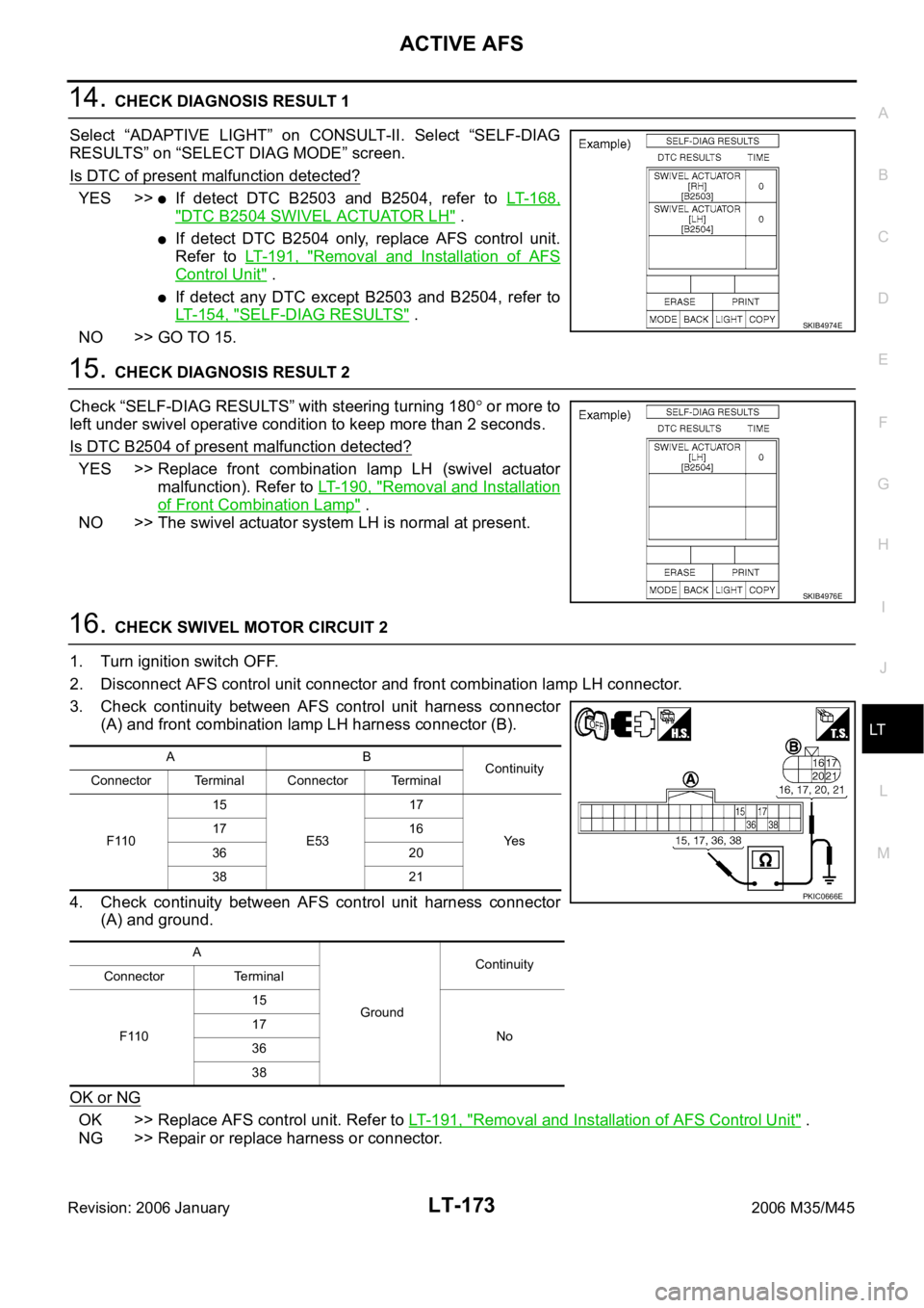
3. Check continuity between AFS control unit harness connector
(A) and front combination lamp LH harness connector (B).
4. Check continuity between AFS control unit harness connector
(A) and ground.
OK or NG
OK >> Replace AFS control unit. Refer to LT-191, "Removal and Installation of AFS Control Unit" .
NG >> Repair or replace harness or connector.
SKIB4974E
SKIB4976E
AB
Continuity
Connector Terminal Connector Terminal
F11015
E5317
Ye s 17 16
36 20
38 21
A
GroundContinuity
Connector Terminal
F11015
No 17
36
38
PKIC0666E
Page 4601 of 5621
LT-174
ACTIVE AFS
Revision: 2006 January2006 M35/M45
DTC B2514 HI SEN UNUSUAL RRNKS003QQ
1. CHECK HEIGHT SENSOR SIGNAL
1. Turn ignition switch ON.
2. Select “ADAPTIVE LIGHT” on CONSULT-II. Select “DATA
MONITOR” on “SELECT DIAG MODE” screen.
3. Check “HI SEN OTP RR” in “Data Monitor”.
OK or NG
OK >> GO TO 2.
NG >>
If voltage is less than approx. 0.25V, GO TO 3.
If voltage is more than approx. 4.75V, GO TO 7.
2. CHECK HEIGHT SENSOR POWER SUPPLY
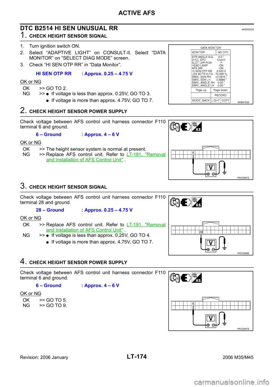
Check voltage between AFS control unit harness connector F110
terminal 6 and ground.
OK or NG
OK >> The height sensor system is normal at present.
NG >> Replace AFS control unit. Refer to LT- 1 9 1 , "
Removal
and Installation of AFS Control Unit" .
3. CHECK HEIGHT SENSOR SIGNAL
Check voltage between AFS control unit harness connector F110
terminal 28 and ground.
OK or NG
OK >> Replace AFS control unit. Refer to LT- 1 9 1 , "Removal
and Installation of AFS Control Unit" .
NG >>
If voltage is less than approx. 0.25V, GO TO 4.
If voltage is more than approx. 4.75V, GO TO 7.
4. CHECK HEIGHT SENSOR POWER SUPPLY
Check voltage between AFS control unit harness connector F110
terminal 6 and ground.
OK or NG
OK >> GO TO 5.
NG >> GO TO 9.HI SEN OTP RR : Approx. 0.25 – 4.75 V
SKIB4793E
6 – Ground : Approx. 4 – 6 V
PKIC0667E
28 – Ground : Approx. 0.25 – 4.75 V
PKIC0668E
6 – Ground : Approx. 4 – 6 V
PKIC0667E
Page 4603 of 5621
LT-176
ACTIVE AFS
Revision: 2006 January2006 M35/M45
8. CHECK HEIGHT SENSOR GROUND CIRCUIT
1. Turn ignition switch OFF.
2. Disconnect AFS control unit connector and height sensor connector.
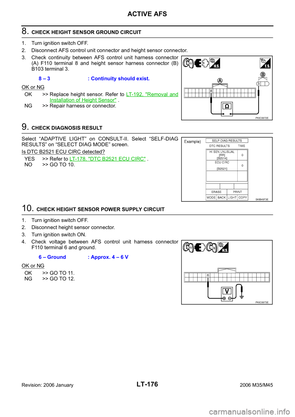
3. Check continuity between AFS control unit harness connector
(A) F110 terminal 8 and height sensor harness connector (B)
B103 terminal 3.
OK or NG
OK >> Replace height sensor. Refer to LT- 1 9 2 , "Removal and
Installation of Height Sensor" .
NG >> Repair harness or connector.
9. CHECK DIAGNOSIS RESULT
Select “ADAPTIVE LIGHT” on CONSULT-II. Select “SELF-DIAG
RESULTS” on “SELECT DIAG MODE” screen.
Is DTC B2521 ECU CIRC detected?
YES >> Refer to LT- 1 7 8 , "DTC B2521 ECU CIRC" .
NO >> GO TO 10.
10. CHECK HEIGHT SENSOR POWER SUPPLY CIRCUIT
1. Turn ignition switch OFF.
2. Disconnect height sensor connector.
3. Turn ignition switch ON.
4. Check voltage between AFS control unit harness connector
F110 terminal 6 and ground.
OK or NG
OK >> GO TO 11.
NG >> GO TO 12.8 – 3 : Continuity should exist.
PKIC0672E
SKIB4973E
6 – Ground : Approx. 4 – 6 V
PKIC0673E
Page 4608 of 5621
ACTIVE AFS
LT-181
C
D
E
F
G
H
I
J
L
MA
B
LT
Revision: 2006 January2006 M35/M45
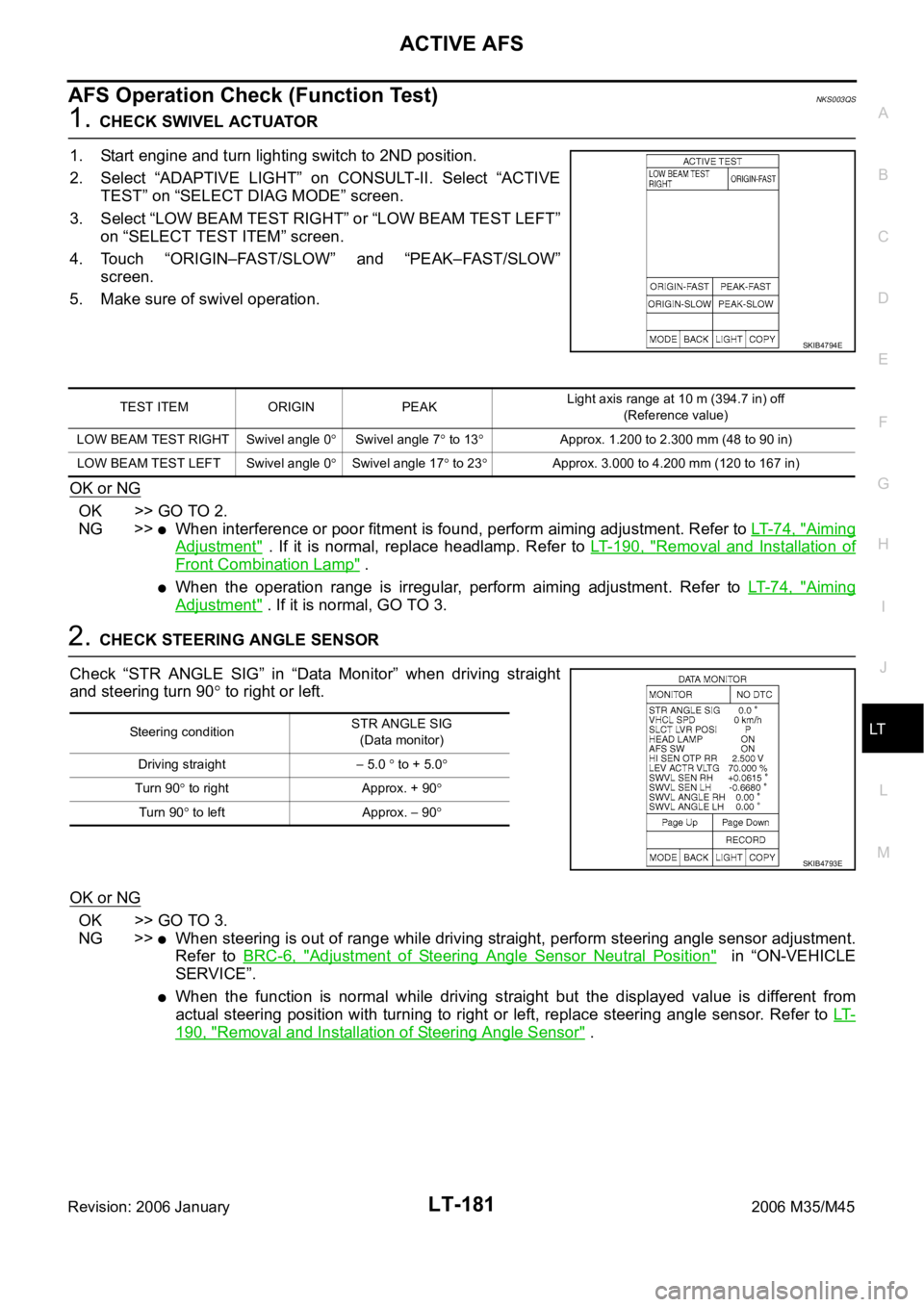
AFS Operation Check (Function Test)NKS003QS
1. CHECK SWIVEL ACTUATOR
1. Start engine and turn lighting switch to 2ND position.
2. Select “ADAPTIVE LIGHT” on CONSULT-II. Select “ACTIVE
TEST” on “SELECT DIAG MODE” screen.
3. Select “LOW BEAM TEST RIGHT” or “LOW BEAM TEST LEFT”
on “SELECT TEST ITEM” screen.
4. Touch “ORIGIN–FAST/SLOW” and “PEAK–FAST/SLOW”
screen.
5. Make sure of swivel operation.
OK or NG
OK >> GO TO 2.
NG >>
When interference or poor fitment is found, perform aiming adjustment. Refer to LT- 7 4 , "Aiming
Adjustment" . If it is normal, replace headlamp. Refer to LT- 1 9 0 , "Removal and Installation of
Front Combination Lamp" .
When the operation range is irregular, perform aiming adjustment. Refer to LT- 7 4 , "Aiming
Adjustment" . If it is normal, GO TO 3.
2. CHECK STEERING ANGLE SENSOR
Check “STR ANGLE SIG” in “Data Monitor” when driving straight
and steering turn 90
to right or left.
OK or NG
OK >> GO TO 3.
NG >>
When steering is out of range while driving straight, perform steering angle sensor adjustment.
Refer to BRC-6, "
Adjustment of Steering Angle Sensor Neutral Position" in “ON-VEHICLE
SERVICE”.
When the function is normal while driving straight but the displayed value is different from
actual steering position with turning to right or left, replace steering angle sensor. Refer to LT-
190, "Removal and Installation of Steering Angle Sensor" .
SKIB4794E
TEST ITEM ORIGIN PEAKLight axis range at 10 m (394.7 in) off
(Reference value)
LOW BEAM TEST RIGHT Swivel angle 0
Swivel angle 7 to 13Approx. 1.200 to 2.300 mm (48 to 90 in)
LOW BEAM TEST LEFT Swivel angle 0
Swivel angle 17 to 23Approx. 3.000 to 4.200 mm (120 to 167 in)
Steering conditionSTR ANGLE SIG
(Data monitor)
Driving straight
5.0 to + 5.0
Turn 90 to right Approx. + 90
Tu rn 90 to left Approx. 90
SKIB4793E
Page 4609 of 5621

LT-182
ACTIVE AFS
Revision: 2006 January2006 M35/M45
3. CHECK SWIVEL ACTUATOR AND AFS CONTROL UNIT
Check “SWVL SEN RH/LH” and “SWVL ANGLE RH/LH” in “Data
Monitor” with steering turning to right or left under swivel operative
condition.
NOTE:
The angle can be slightly different between the displayed value on “SWVL SEN” and
that on “SWVL ANGLE” even when AFS operation is normal.
OK or NG
OK >> AFS function is normal.
NG >>
When the difference is 4.5 or more between the displayed value on “SWVL ANGLE” and that
on “SWVL SEN”, replace headlamp.
When the displayed angle on “SWVL ANGLE” is irregular, replace AFS control unit.
TEST ITEM Turn 180 or more to left Turn 180 or more to right
SWVL SEN RH
SWVL ANGLE RHApprox. 0 7 to 13
SWVL SEN LH
SWVL ANGLE LH 17 to 23Approx. 0
SKIB4793E
Page 4610 of 5621

ACTIVE AFS
LT-183
C
D
E
F
G
H
I
J
L
MA
B
LT
Revision: 2006 January2006 M35/M45
Auto Aiming Operation Check (Function Test)NKS003QT
1. CHECK AIMING MOTOR
1. Start engine and turn lighting switch to 2ND position.
2. Select “ADAPTIVE LIGHT” on CONSULT-II. Select “ACTIVE
TEST” on “SELECT DIAG MODE” screen.
3. Select “LEVELIZER TEST” on “SELECT TEST ITEM” screen.
4. Touch “ORIGIN” and “PEAK” screen.
5. Make sure of auto aiming operation.
OK or NG
OK >> GO TO 2.
NG >>
When interference or poor fitment is found, perform aiming adjustment. Refer to LT- 7 4 , "Aiming
Adjustment" . If it is normal, replace headlamp. Refer to LT- 1 9 0 , "Removal and Installation of
Front Combination Lamp" .
When the operation range is irregular, perform aiming adjustment. Refer to LT- 7 4 , "Aiming
Adjustment" . If it is normal, GO TO 4.
2. PERFORM STATE LEVELIZER ADJUSTMENT 1
Check “LEV ACTR VLTG” in “Data Monitor” with unloaded vehicle
position. (Remove all loads in driver, passenger and trunk rooms.)
OK or NG
OK >> GO TO 3.
NG >> Perform LEVELIZER ADJUSTMENT. Refer to LT- 1 5 3 ,
"WORK SUPPORT (LEVELIZER ADJUSTMENT)" .
3. PERFORM STATE LEVELIZER ADJUSTMENT 2
Check if “LEV ACTR VLTG” changes approx. 3 seconds after lower-
ing vehicle height as low as approx.
0.5V from the value of “HI SEN
OTP RR” in “Data Monitor” at unloaded vehicle position. (Remove all
loads in driver, passenger and trunk rooms.)
OK or NG
OK >> GO TO 4.
NG >> Perform LEVELIZER ADJUSTMENT. Refer to LT- 1 5 3 ,
"WORK SUPPORT (LEVELIZER ADJUSTMENT)" .
SKIB4796E
TEST ITEM ORIGIN PEAK (Reference value)Light axis range at 10 m (394.7 in) off
(Reference value)
LEVELIZER TEST Light axis angle 0
Light axis angle approx. 2.5Approx. 450 mm (17.7 in)
TEST ITEM Unloaded vehicle position
LEV ACTR VLTG Approx. 70%
SKIB4793E
SKIB4793E
Page 4611 of 5621
LT-184
ACTIVE AFS
Revision: 2006 January2006 M35/M45
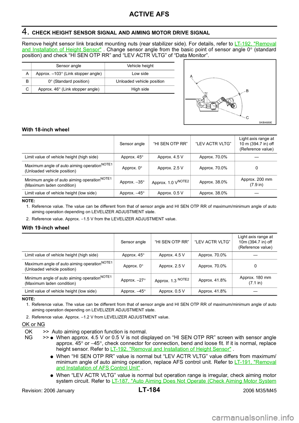
4. CHECK HEIGHT SENSOR SIGNAL AND AIMING MOTOR DRIVE SIGNAL
Remove height sensor link bracket mounting nuts (rear stabilizer side). For details, refer to LT- 1 9 2 , "
Removal
and Installation of Height Sensor" . Change sensor angle from the basic point of sensor angle 0 (standard
position) and check “HI SEN OTP RR” and “LEV ACTR VLTG” of “Data Monitor”.
With 18-inch wheel
NOTE:
1. Reference value. The value can be different from that of sensor angle and HI SEN OTP RR of maximum/minimum angle of auto
aiming operation depending on LEVELIZER ADJUSTMENT state.
2. Reference value. Approx.
1.5 V from the LEVELIZER ADJUSTMENT value.
With 19-inch wheel
NOTE:
1. Reference value. The value can be different from that of sensor angle and HI SEN OTP RR of maximum/minimum angle of auto
aiming operation depending on LEVELIZER ADJUSTMENT state.
2. Reference value. Approx.
1.2 V from LEVELIZER ADJUSTMENT value.
OK or NG
OK >> Auto aiming operation function is normal.
NG >>
When approx. 4.5 V or 0.5 V is not displayed on “HI SEN OTP RR” screen with sensor angle
approx. 45
or 45, check connector for connection, bend and loose fit. If it is normal, replace
height sensor. Refer to LT- 1 9 2 , "
Removal and Installation of Height Sensor" .
When “HI SEN OTP RR” value is normal but “LEV ACTR VLTG” value differs from maximum/
minimum angle of auto aiming operation, replace AFS control unit. Refer to LT- 1 9 1 , "
Removal
and Installation of AFS Control Unit" .
When “LEV ACTR VLTG” value is normal but operation range is irregular, check aiming motor
system circuit. Refer to LT- 1 8 7 , "
Auto Aiming Does Not Operate (Check Aiming Motor System
Sensor angle Vehicle height
A Approx. –103
(Link stopper angle) Low side
B0
(Standard position) Unloaded vehicle position
C Approx. 46
(Link stopper angle) High side
SKIB4689E
Sensor angle “HI SEN OTP RR” “LEV ACTR VLTG”Light axis range at
10 m (394.7 in) off
(Reference value)
Limit value of vehicle height (high side) Approx. 45
Approx. 4.5 V Approx. 70.0% —
Maximum angle of auto aiming operation
NOTE1
(Unloaded vehicle position)Approx. 0Approx. 2.5 V Approx. 70.0% 0
Minimum angle of auto aiming operation
NOTE1
(Maximum laden condition)Approx. 35Approx. 1.0 VNOTE2Approx. 38.0%Approx. 200 mm
(7.9 in)
Limit value of vehicle height (low side) Approx.
45Approx. 0.5 V Approx. 38.0% —
Sensor angle “HI SEN OTP RR” “LEV ACTR VLTG”Light axis range at
10m (394.7 in) off
(Reference value)
Limit value of vehicle height (high side) Approx. 45
Approx. 4.5 V Approx. 70.0% —
Maximum angle of auto aiming operation
NOTE1
(Unloaded vehicle position)Approx. 0Approx. 2.5 V Approx. 70.0% 0
Minimum angle of auto aiming operation
NOTE1
(Maximum laden condition)Approx. 27Approx. 1.3 NOTE2Approx. 41.8%Approx. 180 mm
(7.1 in)
Limit value of vehicle height (low side) Approx.
45Approx. 0.5 V Approx. 41.8% —