Page 5493 of 5621

TF-28
TROUBLE DIAGNOSIS FOR SYSTEM
Revision: 2006 January2006 M35/M45
2. CHECK DTC AFTER DRIVING
1. Turn ignition switch “OFF”.
2. Start engine and drive vehicle at 30 km/h (19 MPH) for at least 1 minute.
3. Make sure that ABS warning lamp turns OFF.
4. Perform erase self-diagnosis results. Refer to TF-22, "
How to Erase Self-Diagnostic Results" .
5. Stop vehicle and turn ignition switch “OFF”.
6. Turn ignition switch “ON”.
7. Perform self-diagnosis.
Is the
“ABS SYSTEM [C1203]” displayed?
YES >> GO TO 3.
NO >>INSPECTION END
3. CHECK AWD CONTROL UNIT
Check AWD control unit input/output signal. Refer to TF-20, "
AWD Control Unit Input/Output Signal Reference
Va l u e s" .
OK or NG
OK >> GO TO 4.
NG >> Check AWD control unit pin terminals for damage or loose connection with harness connector. If
any items are damaged, repair or replace damaged parts.
4. CHECK DTC
Perform the self-diagnosis, after driving a vehicle for a while.
OK or NG
OK >>INSPECTION END
NG >> Perform self-diagnosis with ABS actuator and electric unit (control unit) again. Refer to BRC-23,
"Self-Diagnosis" .
AW D S o l e n oi dNDS000DQ
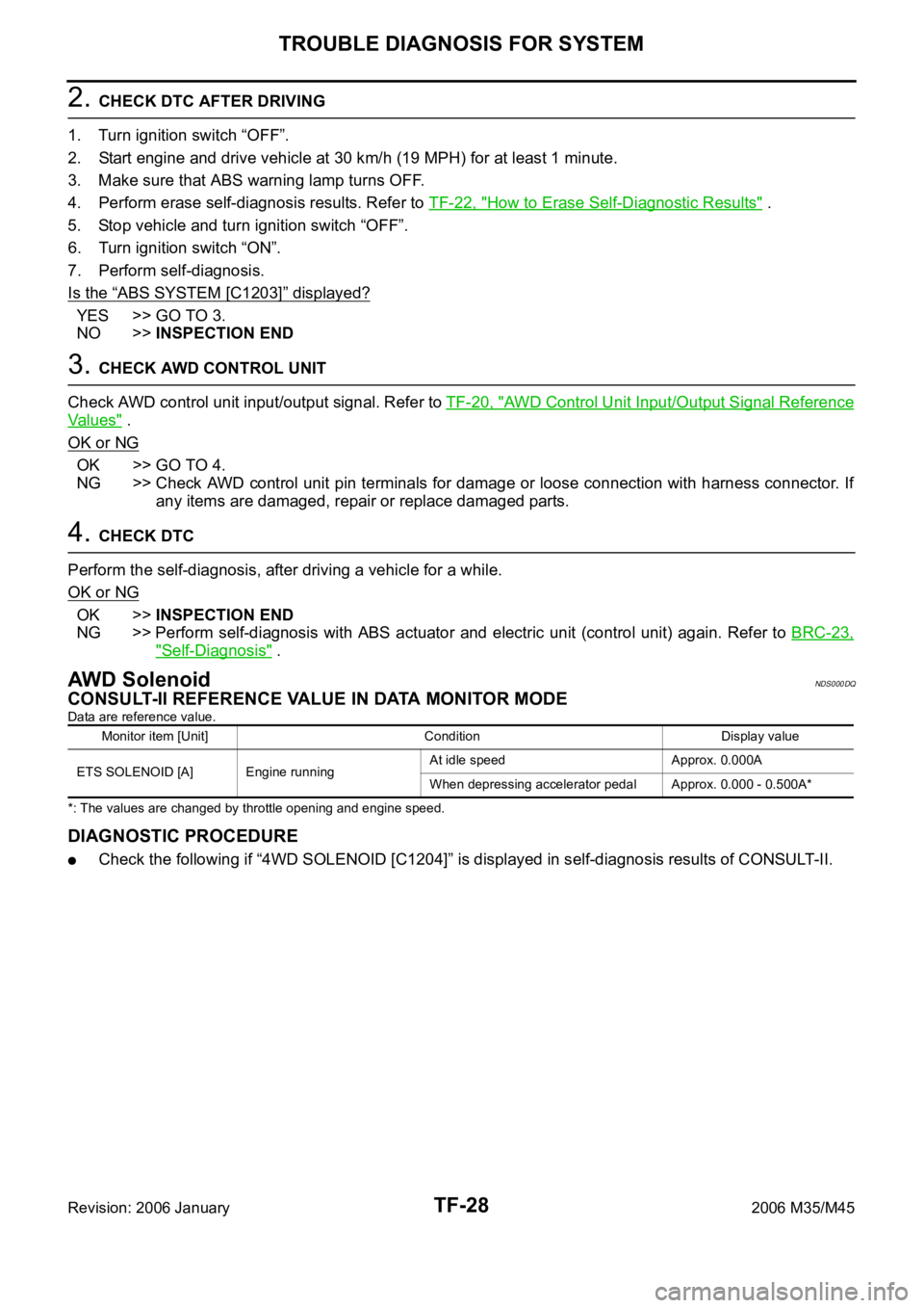
CONSULT-II REFERENCE VALUE IN DATA MONITOR MODE
Data are reference value.
*: The values are changed by throttle opening and engine speed.
DIAGNOSTIC PROCEDURE
Check the following if “4WD SOLENOID [C1204]” is displayed in self-diagnosis results of CONSULT-II.
Monitor item [Unit] Condition Display value
ETS SOLENOID [A] Engine runningAt idle speed Approx. 0.000A
When depressing accelerator pedal Approx. 0.000 - 0.500A*
Page 5538 of 5621

TROUBLE DIAGNOSES
WT-13
C
D
F
G
H
I
J
K
L
MA
B
WT
Revision: 2006 January2006 M35/M45
TROUBLE DIAGNOSESPFP:00004
How to Perform Trouble DiagnosesNES000JU
BASIC CONCEPT
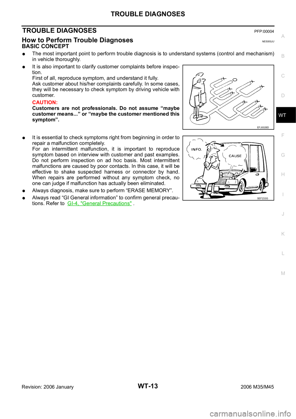
The most important point to perform trouble diagnosis is to understand systems (control and mechanism)
in vehicle thoroughly.
It is also important to clarify customer complaints before inspec-
tion.
First of all, reproduce symptom, and understand it fully.
Ask customer about his/her complaints carefully. In some cases,
they will be necessary to check symptom by driving vehicle with
customer.
CAUTION:
Customers are not professionals. Do not assume “maybe
customer means...” or “maybe the customer mentioned this
symptom”.
It is essential to check symptoms right from beginning in order to
repair a malfunction completely.
For an intermittent malfunction, it is important to reproduce
symptom based on interview with customer and past examples.
Do not perform inspection on ad hoc basis. Most intermittent
malfunctions are caused by poor contacts. In this case, it will be
effective to shake suspected harness or connector by hand.
When repairs are performed without any symptom check, no
one can judge if malfunction has actually been eliminated.
Always diagnosis, make sure to perform “ERASE MEMORY”.
Always read “GI General information” to confirm general precau-
tions. Refer to GI-4, "
General Precautions" .
EFJ0028D
SEF233G
Page 5548 of 5621

TROUBLE DIAGNOSES
WT-23
C
D
F
G
H
I
J
K
L
MA
B
WT
Revision: 2006 January2006 M35/M45
NOTICE:
186 kPa (1.86 kg/cm2 , 27 psi): Standard air pressure is for 230 kpa (2.3 kg/cm2 , 33 psi) vehicles.
How to Erase Self-Diagnostic Results
1. Perform applicable inspection of malfunctioning item and then repair or replace.
2. Start engine, and touch “START (NISSAN BASED VHCL)” “ AIR PRESSURE MONITOR” “SELF-DIAG
RESULTS” “ERASE” in this order to erase the diagnostic memory.
CAUTION:
If memory cannot be erased, repeat step 1, 2.
3. Perform self-diagnosis again, and make sure that DTC memory is erased.
DATA MONITOR MODE
Operation Procedure
1. Perform “CONSULT-II Start Procedure”. Refer to GI-39, "CONSULT-II Start Procedure" .
2. Touch “DATA MONITOR”.
3. Select from “SELECT MONITOR ITEM”, screen of data monitor is displayed.
NOTE:
When malfunction is detected, CONSULT-II performs REAL-TIME DIAGNOSIS. Also, any malfunction
detected while in this mode will be displayed in real time.
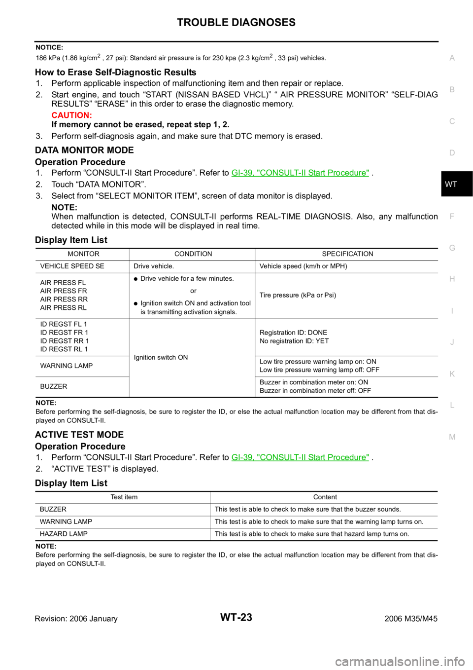
Display Item List
NOTE:
Before performing the self-diagnosis, be sure to register the ID, or else the actual malfunction location may be different from that dis-
played on CONSULT-II.
ACTIVE TEST MODE
Operation Procedure
1. Perform “CONSULT-II Start Procedure”. Refer to GI-39, "CONSULT-II Start Procedure" .
2. “ACTIVE TEST” is displayed.
Display Item List
NOTE:
Before performing the self-diagnosis, be sure to register the ID, or else the actual malfunction location may be different from that dis-
played on CONSULT-II.MONITOR CONDITION SPECIFICATION
VEHICLE SPEED SE Drive vehicle. Vehicle speed (km/h or MPH)
AIR PRESS FL
AIR PRESS FR
AIR PRESS RR
AIR PRESS RL
Drive vehicle for a few minutes.
Tire pressure (kPa or Psi) or
Ignition switch ON and activation tool
is transmitting activation signals.
ID REGST FL 1
ID REGST FR 1
ID REGST RR 1
ID REGST RL 1
Ignition switch ONRegistration ID: DONE
No registration ID: YET
WARNING LAMPLow tire pressure warning lamp on: ON
Low tire pressure warning lamp off: OFF
BUZZERBuzzer in combination meter on: ON
Buzzer in combination meter off: OFF
Test item Content
BUZZER This test is able to check to make sure that the buzzer sounds.
WARNING LAMP This test is able to check to make sure that the warning lamp turns on.
HAZARD LAMP This test is able to check to make sure that hazard lamp turns on.