2006 INFINITI M35 relay
[x] Cancel search: relayPage 1069 of 5621

BL-130
INTELLIGENT KEY SYSTEM/ENGINE START FUNCTION
Revision: 2006 January2006 M35/M45
starter motor relay. (If the engine initiating has failed, the cranking will stop automatically within 5 sec-
onds.)
CAUTION:
When the Intelligent Key is carried outside of the vehicle (inside key antenna detection area) with
the power supply in ACC or ON position, even if the engine start condition* is satisfied, the engine
cannot be started.
*: For the engine start condition, refer to BL-130, "
PUSH-BUTTON IGNITION SWITCH OPERATION PROCE-
DURE" .
Operation Range
Engine can be started when Intelligent Key is inside the vehicle. However, sometimes engine might not start
when Intelligent Key is on instrument panel or in glove box.
OPERATION WHEN KEY SLOT IS USED
When the Intelligent Key battery is discharged, it performs the immobilizer ID verification between the inte-
grated transponder and BCM by inserting the Intelligent Key into the key slot, and then the engine can be
started.
For details relating to starting the engine using key slot, refer to BL-248, "
IVIS (INFINITI VEHICLE IMMOBI-
LIZER SYSTEM-NATS)" .
PUSH-BUTTON IGNITION SWITCH OPERATION PROCEDURE
The power supply position changing operation can be performed with the following operation.
NOTE:
When an Intelligent Key is within the detection area of inside key antenna and when it is inserted to the
key slot, it is equivalent to the operations below.
When starting the engine, the Intelligent Key unit monitors the engine start conditions (brake pedal operat-
ing condition, A/T selector lever position, and vehicle speed).
Unless each start condition is fulfilled, the engine will not respond regardless of how many times the
engine switch is pushed. At that time, illumination repeats the position in the order of LOCK
AC-
C
ONLOCK.
Power supply positionEngine start/stop condition
Push-button ignition switch
operation frequency
Brake pedal A/T selector lever position
LOCK
ACCNot depressed
(When A/T selector lever is in any
position other than P or N, there
will be no effect even if it is
depressed.)Any position other than P or N
(When the brake pedal is not
depressed, there will be no effect
even if the A/T selector lever is in
P or N position.)1
LOCK
ACC ONNot depressed
(When A/T selector lever is in any
position other than P or N, there
will be no effect even if it is
depressed.)Any position other than P or N
(When the brake pedal is not
depressed, there will be no effect
even if the A/T selector lever is in
P or N position.)2
LOCK
ACC ON
LOCKNot depressed
(When A/T selector lever is in any
position other than P or N, there
will be no effect even if it is
depressed.)Any position other than P or N
(When the brake pedal is not
depressed, there will be no effect
even if the A/T selector lever is in
P or N position.)3
LOCK
START
ACC
START
ON
START
(Engine start)Depressed P or N position (*1)1
[If the switch is pushed once,
the engine starts from any
power supply position (LOCK,
ACC, and ON)]
Engine is running
LOCK
(Engine stop)— P position 1
Page 1083 of 5621

BL-144
INTELLIGENT KEY SYSTEM/ENGINE START FUNCTION
Revision: 2006 January2006 M35/M45
10 VPush-button ignition
switch ON indicatorONPush-button ignition switch is in ON
position0
—Push-button ignition switch is in any
position
(Except ON position)1.2
11 P Stop lamp switch —Brake pedal depressed Battery voltage
Brake pedal released Battery voltage
12 L/RPush-button ignition
switch illumination—Push-button ignition switch illumina-
tion is turned on2.6
Push-button ignition switch illumina-
tion is turned off
(15 seconds or more after the driver
door is closed)0
13 LG/B Key slot illumination LOCKInsert Intelligent Key into key slot and
driver side door is open.Battery voltage
Remove Intelligent Key from key slot. 0
15 LGSteering lock unit
power sourceLOCK — Battery voltage
16 P/BSteering lock unit sig-
nalLOCK Steering lock: Lock Battery voltage
ACC
Steering lock: Unlock
(Unlocked moment)0
NO 0
17 OSteering lock unit con-
dition signal-1LOCK Steering lock: Lock 0
ACC
Steering lock: UnlockBattery voltage
ON Battery voltage
18 L/YSteering lock unit con-
dition signal-2LOCK Steering lock: Lock Battery voltage
ACC
Steering lock: Unlock0
ON 0
19 BR/Y Key switch signal LOCKInsert Intelligent Key into key slot. 0
Remove Intelligent Key from key slot Battery voltage
20 B Ground — — 0
27 VA/T device (Detention
switch)LOCK A/T selector lever is in P position 0
ON Other than above Battery voltage
28 SB Starter relayON A/T selector lever is in N or P position Battery voltage
—Ignition switch position is in LOCK
position or A/T selector lever is in any
position other than N or P position0
29 V/R Stop lamp switch —Brake pedal depressed Battery voltage
Brake pedal released 0
30 L/WIgnition power supply
(ACC)ACCIgnition switch position is in ACC or
ON positionBattery voltage
31 GRIgnition power supply
(ON)ONIgnition switch position is in ON or
START positionBattery voltage
33 O PDU signalLOCK Steering lock: Lock 0
ACC Steering lock: Unlock 8 Te r m i -
nal
No.Wire
color
ItemCondition
Voltage (V)
(Approx.) Push-
button
ignition
switch
positionOperation or conditions
Page 1087 of 5621

BL-148
INTELLIGENT KEY SYSTEM/ENGINE START FUNCTION
Revision: 2006 January2006 M35/M45
Terminals and Reference Value for PDUNIS001YI
Te r -
minal
No.Wire
colorItemCondition
Voltage (V)
(Approx.) Push-
button
ignition
switch
positionOperation or conditions
1 P Wake up signalLOCKSleep condition (30 seconds or more
after all doors are closed under the con-
dition that the power supply position is in
the LOCK position)Battery voltage
— Wake-up condition (Open driver door) 0
2 G Starter control signalON At starter motor cranking 0
— Any condition other than above Battery voltage
3GRSteering lock unit
power sourceLOCKPush-button ignition switch is pressed
under the condition that Intelligent Key is
in the vehicle or Intelligent Key is inserted0
Battery voltage 0
— Any condition other than above 0
6VSteering lock control
signal-1—Push-button ignition switch is pressed
under the condition that Intelligent Key is
in the vehicle or Intelligent Key is insertedBattery voltage
LOCKPower supply position is in LOCK posi-
tion
(Steering lock activated)Battery voltage
0 Battery volt-
age
(Battery voltage is detected when
activating the steering lock)
7LGSteering lock control
signal-2—Push-button ignition switch is pressed
under the condition that Intelligent Key is
in the vehicle or Intelligent Key is insertedBattery voltage
LOCKPower supply position is in LOCK posi-
tion
(Steering lock activated)Battery voltage
0 Battery volt-
age
(Battery voltage is detected when
activating the steering lock)
9OSteering lock feed
back signal— Steering lock: Lock 0
LOCK Steering lock: Unlock 8
10 B Ground — — 0
11 YIPDM E/R current sig-
nalSTART At starter motor cranking 5
LOCK Any condition other than above 2
12 R Feed back signalLOCKSleep condition (30 seconds or more
after all doors are closed under the con-
dition that the power supply position is in
the LOCK position)1
—Wake-up condition (any condition other
than above)0
13 R Starter relaySTART At starter motor cranking Battery voltage
— Any condition other than above 4
14 SB Power source (fuse) — — Battery voltage
15 LPower source (fusible
link)— — Battery voltage
17 GPower source (fusible
link)— — Battery voltage
Page 1092 of 5621
![INFINITI M35 2006 Factory Service Manual INTELLIGENT KEY SYSTEM/ENGINE START FUNCTION
BL-153
C
D
E
F
G
H
J
K
L
MA
B
BL
Revision: 2006 January2006 M35/M45
CAUTION:
When CAN COMM 1 [U1000] and CAN COMM 2 [U1010] are displayed, give priority to INFINITI M35 2006 Factory Service Manual INTELLIGENT KEY SYSTEM/ENGINE START FUNCTION
BL-153
C
D
E
F
G
H
J
K
L
MA
B
BL
Revision: 2006 January2006 M35/M45
CAUTION:
When CAN COMM 1 [U1000] and CAN COMM 2 [U1010] are displayed, give priority to](/manual-img/42/57023/w960_57023-1091.png)
INTELLIGENT KEY SYSTEM/ENGINE START FUNCTION
BL-153
C
D
E
F
G
H
J
K
L
MA
B
BL
Revision: 2006 January2006 M35/M45
CAUTION:
When CAN COMM 1 [U1000] and CAN COMM 2 [U1010] are displayed, give priority to performing trouble diagnosis.
DATA MONITOR
ENG START SW
[B2556]Condition that push-button ignition switch is pushed is
detected continuously for 100 seconds or moreCheck push-button igni-
tion switchBL-168
VEHICLE SPEED
[B2557]Some differences occur on one or more vehicle speed
inputs of Intelligent Key unitCheck vehicle speed sig-
nalBL-169
SHIFT POSITION
[B2558]
There is a difference between the shift position input
via CAN communication and the P position input by
detent switch
Vehicle speed (5 km/h or more) is detected continu-
ously for 10 seconds or more even if the shift posi-
tion is detected in P position when the power supply
position is in ON positionCheck shift position inputBL-172
PDU
[B2559]Internal malfunction is detected in PDU Replace PDUBL-174
START POW SUP CIRC
[B2560]Though the engine start operation is not performed,
starter relay in IPDM E/R is ONCheck starter power sup-
plyBL-174
LOW VOLTAGE
[B2562]Battery power supply input to Intelligent Key unit (8.8V
or less) is detected continuously for 1.5 seconds or
moreCheck battery low volt-
ageBL-177
HI VOLTAGE
[B2563]Battery power supply input to Intelligent Key unit (18V
or more) is detected continuously for 90 seconds or
moreCheck for battery high
voltageBL-178
NATS MALFUNCTION
[B2590]Malfunction is detected in immobilizer systemCheck (IVIS) NATS trou-
ble diagnosis procedureBL-268
Suspect Systems
[DTC]Diagnostic item is detected when... Repair work Reference page
Monitor item Content
DR REQ SW Indicates [ON/OFF] condition of door request switch (driver side).
AS REQ SW Indicates [ON/OFF] condition of door request switch (passenger side).
BD/TR REQ SW Indicates [ON/OFF] condition of trunk opener request switch.
ON POS Indicates [ON/OFF] condition of ignition switch in ON position.
ACC POS Indicates [ON/OFF] condition of ignition switch in ACC position.
DOOR STAT SW Indicates [ON/OFF] condition of door unlock sensor.
STOP LAMP SW Indicates [ON/OFF] condition of stop lamp switch.
P RANGE SW Indicates [ON/OFF] condition of park position switch.
TR CANCEL SW* Indicates [ON/OFF] condition of trunk cancel switch.
DOOR LOCK SIG* Indicates [ON/OFF] condition of door lock signal from Intelligent Key remote controller button.
DOOR UNLOCK SIG* Indicates [ON/OFF] condition of door unlock signal from Intelligent Key remote controller button.
KEYLESS TRUNK* Indicates [ON/OFF] condition of trunk open signal from Intelligent Key remote controller button.
KEYLESS PANIC* Indicates [ON/OFF] condition of panic alarm signal from Intelligent Key remote controller button.
DOOR SW DR*Indicates [OPEN/CLOSE] condition of front door switch driver side from BCM via CAN communica-
tion line.
DOOR SW AS*Indicates [OPEN/CLOSE] condition of front door switch passenger side from BCM via CAN commu-
nication line.
DOOR SW RR* Indicates [OPEN/CLOSE] condition of rear door switch LH from BCM via CAN communication line.
DOOR SW RL* Indicates [OPEN/CLOSE] condition of rear door switch RH from BCM via CAN communication line.
DOOR BK SW* Indicates [OPEN/CLOSE] condition of back door switch from BCM via CAN communication line.
Page 1106 of 5621

INTELLIGENT KEY SYSTEM/ENGINE START FUNCTION
BL-167
C
D
E
F
G
H
J
K
L
MA
B
BL
Revision: 2006 January2006 M35/M45
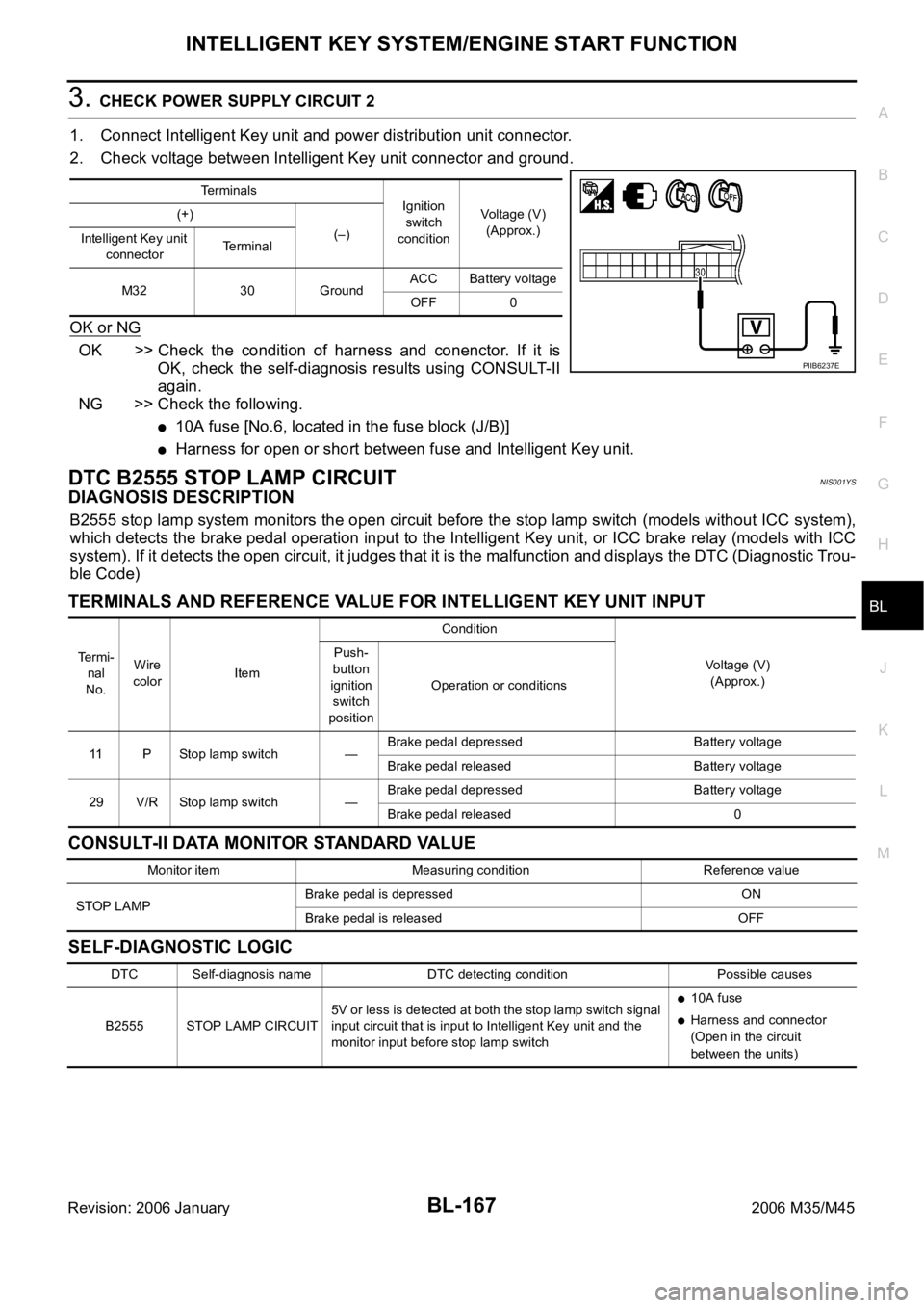
3. CHECK POWER SUPPLY CIRCUIT 2
1. Connect Intelligent Key unit and power distribution unit connector.
2. Check voltage between Intelligent Key unit connector and ground.
OK or NG
OK >> Check the condition of harness and conenctor. If it is
OK, check the self-diagnosis results using CONSULT-II
again.
NG >> Check the following.
10A fuse [No.6, located in the fuse block (J/B)]
Harness for open or short between fuse and Intelligent Key unit.
DTC B2555 STOP LAMP CIRCUITNIS001YS
DIAGNOSIS DESCRIPTION
B2555 stop lamp system monitors the open circuit before the stop lamp switch (models without ICC system),
which detects the brake pedal operation input to the Intelligent Key unit, or ICC brake relay (models with ICC
system). If it detects the open circuit, it judges that it is the malfunction and displays the DTC (Diagnostic Trou-
ble Code)
TERMINALS AND REFERENCE VALUE FOR INTELLIGENT KEY UNIT INPUT
CONSULT-II DATA MONITOR STANDARD VALUE
SELF-DIAGNOSTIC LOGIC
Terminals
Ignition
switch
conditionVoltage (V)
(Approx.) (+)
(–)
Intelligent Key unit
connectorTe r m i n a l
M32 30 GroundACC Battery voltage
OFF 0
PIIB6237E
Te r m i -
nal
No.Wire
colorItemCondition
Voltage (V)
(Approx.) Push-
button
ignition
switch
positionOperation or conditions
11 P Stop lamp switch —Brake pedal depressed Battery voltage
Brake pedal released Battery voltage
29 V/R Stop lamp switch —Brake pedal depressed Battery voltage
Brake pedal released 0
Monitor item Measuring condition Reference value
STOP LAMPBrake pedal is depressed ON
Brake pedal is released OFF
DTC Self-diagnosis name DTC detecting condition Possible causes
B2555 STOP LAMP CIRCUIT5V or less is detected at both the stop lamp switch signal
input circuit that is input to Intelligent Key unit and the
monitor input before stop lamp switch
10A fuse
Harness and connector
(Open in the circuit
between the units)
Page 1111 of 5621

BL-172
INTELLIGENT KEY SYSTEM/ENGINE START FUNCTION
Revision: 2006 January2006 M35/M45
DTC B2558 SHIFT POSITIONNIS001YV
DIAGNOSIS DESCRIPTION
B2558 shift position input system monitors the A/T selector lever position. If there is the difference between
the input from A/T device, the input from A/T assembly, and CAN communication input from A/T control unit, it
judges that it is the malfunction and displays the DTC (Diagnostic Trouble Code)
TERMINALS AND REFERENCE VALUE FOR INTELLIGENT KEY UNIT
SELF-DIAGNOSTIC LOGIC
DIAGNOSTIC PROCEDURE
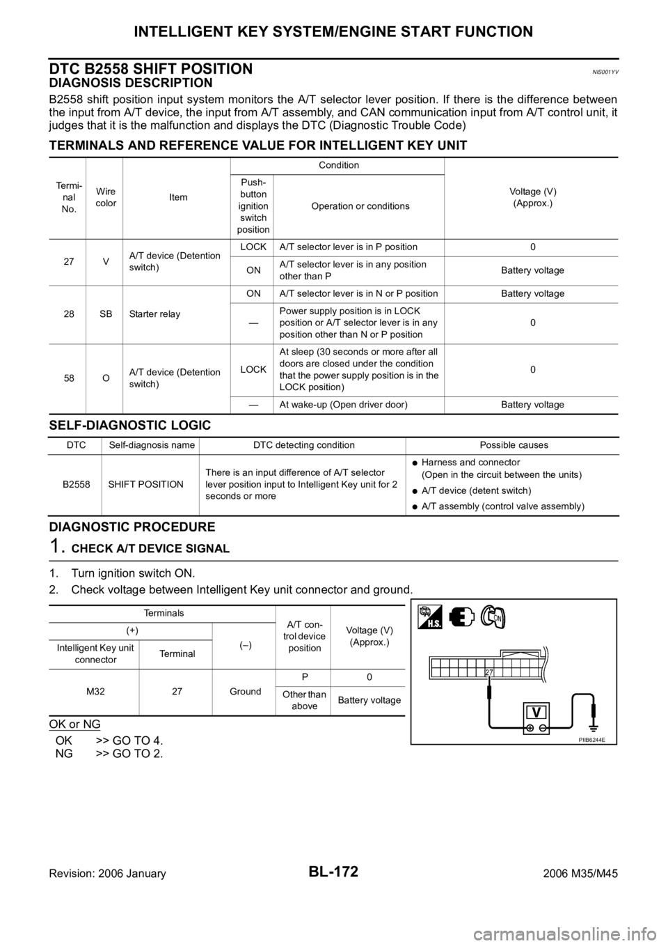
1. CHECK A/T DEVICE SIGNAL
1. Turn ignition switch ON.
2. Check voltage between Intelligent Key unit connector and ground.
OK or NG
OK >> GO TO 4.
NG >> GO TO 2.
Te r m i -
nal
No.Wire
colorItemCondition
Voltage (V)
(Approx.) Push-
button
ignition
switch
positionOperation or conditions
27 VA/T device (Detention
switch)LOCK A/T selector lever is in P position 0
ONA/T selector lever is in any position
other than PBattery voltage
28 SB Starter relayON A/T selector lever is in N or P position Battery voltage
—Power supply position is in LOCK
position or A/T selector lever is in any
position other than N or P position0
58 OA/T device (Detention
switch)LOCKAt sleep (30 seconds or more after all
doors are closed under the condition
that the power supply position is in the
LOCK position)0
— At wake-up (Open driver door) Battery voltage
DTC Self-diagnosis name DTC detecting condition Possible causes
B2558 SHIFT POSITIONThere is an input difference of A/T selector
lever position input to Intelligent Key unit for 2
seconds or more
Harness and connector
(Open in the circuit between the units)
A/T device (detent switch)
A/T assembly (control valve assembly)
Terminals
A/T con-
trol device
positionVoltage (V)
(Approx.) (+)
(–)
Intelligent Key unit
connectorTerminal
M32 27 GroundP0
Other than
aboveBattery voltage
PIIB6244E
Page 1113 of 5621

BL-174
INTELLIGENT KEY SYSTEM/ENGINE START FUNCTION
Revision: 2006 January2006 M35/M45
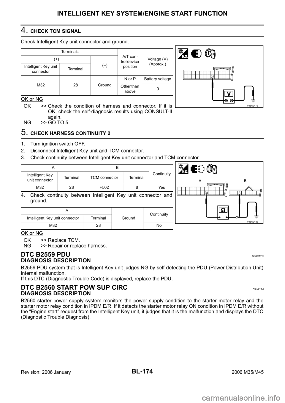
4. CHECK TCM SIGNAL
Check Intelligent Key unit connector and ground.
OK or NG
OK >> Check the condition of harness and connector. If it is
OK, check the self-diagnosis results using CONSULT-II
again.
NG >> GO TO 5.
5. CHECK HARNESS CONTINUITY 2
1. Turn ignition switch OFF.
2. Disconnect Intelligent Key unit and TCM connector.
3. Check continuity between Intelligent Key unit connector and TCM connector.
4. Check continuity between Intelligent Key unit connector and
ground.
OK or NG
OK >> Replace TCM.
NG >> Repair or replace harness.
DTC B2559 PDUNIS001YW
DIAGNOSIS DESCRIPTION
B2559 PDU system that is Intelligent Key unit judges NG by self-detecting the PDU (Power Distribution Unit)
internal malfunction.
If this DTC (Diagnostic Trouble Code) is displayed, replace the PDU.
DTC B2560 START POW SUP CIRCNIS001YX
DIAGNOSIS DESCRIPTION
B2560 starter power supply system monitors the power supply condition to the starter motor relay and the
starter motor relay condition in IPDM E/R. If it detects the starter motor relay ON condition in IPDM E/R without
the “Engine start” request from the Intelligent Key unit, it judges that it is the malfunction and displays the DTC
(Diagnostic Trouble Diagnosis).
Terminals
A/T con-
trol device
positionVoltage (V)
(Approx.) (+)
(–)
Intelligent Key unit
connectorTerminal
M32 28 GroundN or P Battery voltage
Other than
above0
PIIB6247E
AB
Continuity
Intelligent Key
unit connectorTerminal TCM connector Terminal
M32 28 F502 8 Yes
A
GroundContinuity
Intelligent Key unit connector Terminal
M32 28 No
PIIB6248E
Page 1114 of 5621

INTELLIGENT KEY SYSTEM/ENGINE START FUNCTION
BL-175
C
D
E
F
G
H
J
K
L
MA
B
BL
Revision: 2006 January2006 M35/M45
TERMINALS AND REFERENCE VALUE
Intelligent Key Unit
PDU (Power Distribution Unit)
SELF-DIAGNOSTIC LOGIC
DIAGNOSTIC PROCEDURE
1. CHECK HARNESS CONTINUITY 1
1. Turn ignition switch OFF.
2. Disconnect Intelligent Key unit and power distribution unit connector.
3. Check continuity between Intelligent Key unit connector and power distribution unit connector.
4. Check continuity between Intelligent Key unit connector and
ground.
OK or NG
OK >> GO TO 2.
NG >> Repair or replace harness.
Te r m i -
nal
No.Wire
colorItemCondition
Voltage (V)
(Approx.) Push-
button
ignition
switch
positionOperation or conditions
3YIPDM E/R current sig-
nalSTART At starter motor cranking 5
LOCK Any condition other than above 2
Te r -
minal
No.Wire
colorItemCondition
Voltage (V)
(Approx.) Push-
button
ignition
switch
positionOperation or conditions
13 R Starter relaySTART At starter motor cranking Battery voltage
— Any condition other than above 4
DTC Self-diagnosis name DTC detecting condition Possible causes
B2560START POW SUP
CIRCIt is detected that the power is supplied to the
starter motor without the engine start request from
the Intelligent Key unit
Harness and connector
(Open in the circuit between
the units)
PDU
IPDM E/R
AB
Continuity
Intelligent Key
unit connectorTerminalPower distribution
unit connectorTerminal
M32 3 M30 11 Yes
A
GroundContinuity
Intelligent Key unit connector Terminal
M32 3 No
PIIB6249E