2006 INFINITI M35 oil change
[x] Cancel search: oil changePage 3505 of 5621

GI-42
LIFTING POINT
Revision: 2006 January2006 M35/M45
LIFTING POINTPFP:00000
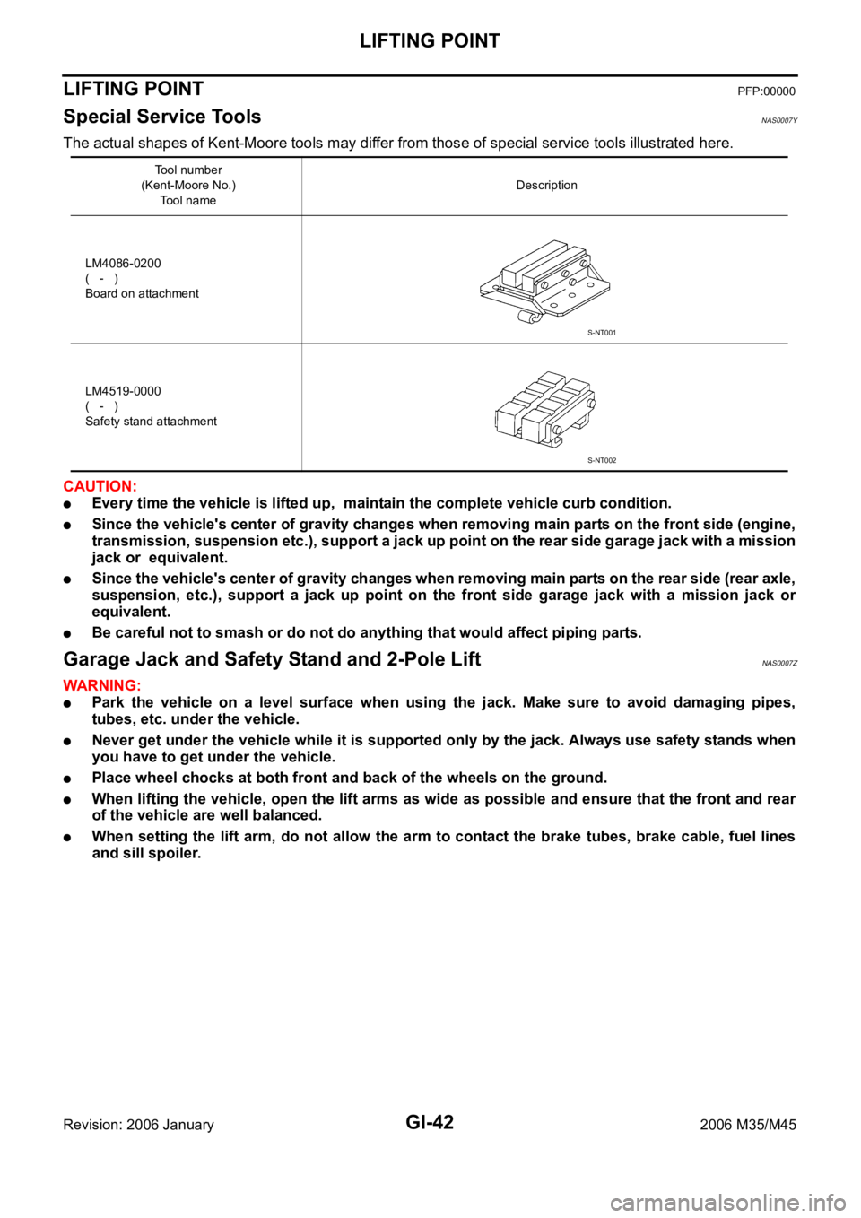
Special Service Tools NAS0007Y
The actual shapes of Kent-Moore tools may differ from those of special service tools illustrated here.
CAUTION:
Every time the vehicle is lifted up, maintain the complete vehicle curb condition.
Since the vehicle's center of gravity changes when removing main parts on the front side (engine,
transmission, suspension etc.), support a jack up point on the rear side garage jack with a mission
jack or equivalent.
Since the vehicle's center of gravity changes when removing main parts on the rear side (rear axle,
suspension, etc.), support a jack up point on the front side garage jack with a mission jack or
equivalent.
Be careful not to smash or do not do anything that would affect piping parts.
Garage Jack and Safety Stand and 2-Pole LiftNAS0007Z
WAR NING :
Park the vehicle on a level surface when using the jack. Make sure to avoid damaging pipes,
tubes, etc. under the vehicle.
Never get under the vehicle while it is supported only by the jack. Always use safety stands when
you have to get under the vehicle.
Place wheel chocks at both front and back of the wheels on the ground.
When lifting the vehicle, open the lift arms as wide as possible and ensure that the front and rear
of the vehicle are well balanced.
When setting the lift arm, do not allow the arm to contact the brake tubes, brake cable, fuel lines
and sill spoiler.
Tool number
(Kent-Moore No.)
Tool nameDescription
LM4086-0200
( - )
Board on attachment
LM4519-0000
( - )
Safety stand attachment
S-NT001
S-NT002
Page 4622 of 5621

FRONT FOG LAMP
LT-195
C
D
E
F
G
H
I
J
L
MA
B
LT
Revision: 2006 January2006 M35/M45
FOG LAMP OPERATION
The fog lamp switch is built in combination switch. The lighting switch must be in 2ND position or AUTO posi-
tion (headlamp is ON) and fog lamp switch must be ON for fog lamp operation.
With the fog lamp switch in the ON position, the CPU located in IPDM E/R grounds coil side of the fog lamp
relay. Fog lamp relay then directs power
through IPDM E/R terminal 37
to front fog lamp RH terminal 1,
through IPDM E/R terminal 36
to front fog lamp LH terminal 1.
Ground is supplied
to front fog lamp RH terminal 2
through grounds E22 and E43,
to front fog lamp LH terminal 2
through grounds E22 and E43.
With power and grounds supplied, the front fog lamps illuminate.
The unified meter and A/C amp. that received the front fog lamp request signal by BCM across the CAN com-
munication makes a front fog lamp indicator lamp turn on in combination meter.
COMBINATION SWITCH READING FUNCTION
Refer to BCS-3, "COMBINATION SWITCH READING FUNCTION" .
EXTERIOR LAMP BATTERY SAVER CONTROL
When the combination switch (lighting switch) is in the 2ND position (ON), and the ignition switch is turned
from ON or ACC to OFF, the battery saver control function is activated.
Under this condition, the headlamps remain illuminated for 5 minutes, then the headlamps are turned off.
Exterior lamp battery saver control mode can be changed by the function setting of CONSULT-II.
CAN Communication System DescriptionNKS003R4
CAN (Controller Area Network) is a serial communication line for real time application. It is an on-vehicle mul-
tiplex communication line with high data communication speed and excellent error detection ability. Many elec-
tronic control units are equipped onto a vehicle, and each control unit shares information and links with other
control units during operation (not independent). In CAN communication, control units are connected with 2
communication lines (CAN H line, CAN L line) allowing a high rate of information transmission with less wiring.
Each control unit transmits/receives data but selectively reads required data only.
CAN Communication UnitNKS003R5
Refer to LAN-34, "CAN Communication Unit" .
Page 4677 of 5621

LT-250
PARKING, LICENSE PLATE AND TAIL LAMPS
Revision: 2006 January2006 M35/M45
With the ignition switch in the ON or START position, power is supplied
to CPU located in IPDM E/R,
through 15A fuse [No. 1, located in fuse block (J/B)]
to BCM terminal 38.
With the ignition switch in the ACC or ON position, power is supplied
through 10A fuse [No. 6, located in fuse block (J/B)]
to BCM terminal 11.
Ground is supplied
to BCM terminal 52
through grounds M16 and M70,
to IPDM E/R terminals 38 and 51
through grounds E22 and E43.
OPERATION BY LIGHTING SWITCH
With the lighting switch in the 1ST or 2ND position (or if the auto light system is activated), the BCM receives
input signal requesting the parking, license plate and tail lamps to illuminate. This input signal is communi-
cated to the IPDM E/R across the CAN communication lines. The CPU located in the IPDM E/R controls the
tail lamp relay coil, which when energized, directs power
through IPDM E/R terminal 21
to front combination lamp LH and RH terminals 5 (parking)
to front combination lamp LH and RH terminals 7 (side marker)
to rear combination lamp LH and RH terminals 1 (tail and side marker)
to license plate lamp LH and RH terminals 1.
Ground is supplied at all times
to front combination lamp LH and RH terminals 1 (parking and side marker)
through grounds E22 and E43,
to rear combination lamp LH and RH terminals 4 (tail and side marker)
to license plate lamp LH and RH terminals 2
through grounds B5, B40 and B131.
With power and ground supplied, the parking, license plate and tail lamps illuminate.
COMBINATION SWITCH READING FUNCTION
Refer toBCS-3, "COMBINATION SWITCH READING FUNCTION" .
EXTERIOR LAMP BATTERY SAVER CONTROL
When the combination switch (lighting switch) is in the 1ST (or 2ND) position, and ignition switch is turned
from ON or ACC to OFF, battery saver control feature is activated.
Under this condition, parking, license plate, side marker and tail lamps remain illuminated for 5 minutes, then
the parking, license plate, side marker and tail lamps are turned off.
Exterior lamp battery saver control mode can be changed by the function setting of CONSULT-II.
CAN Communication System DescriptionNKS003SJ
CAN (Controller Area Network) is a serial communication line for real time application. It is an on-vehicle mul-
tiplex communication line with high data communication speed and excellent error detection ability. Many elec-
tronic control units are equipped onto a vehicle, and each control unit shares information and links with other
control units during operation (not independent). In CAN communication, control units are connected with 2
communication lines (CAN H line, CAN L line) allowing a high rate of information transmission with less wiring.
Each control unit transmits/receives data but selectively reads required data only.
CAN Communication UnitNKS003SK
Refer to LAN-34, "CAN Communication Unit" .
Page 4752 of 5621
![INFINITI M35 2006 Factory Service Manual ENGINE OIL
LU-9
[VQ35DE]
C
D
E
F
G
H
I
J
K
L
MA
LU
Revision: 2006 January2006 M35/M45
a. Remove old liquid gasket adhering to oil pressure switch and the mating surface.
b. Apply liquid gasket and tig INFINITI M35 2006 Factory Service Manual ENGINE OIL
LU-9
[VQ35DE]
C
D
E
F
G
H
I
J
K
L
MA
LU
Revision: 2006 January2006 M35/M45
a. Remove old liquid gasket adhering to oil pressure switch and the mating surface.
b. Apply liquid gasket and tig](/manual-img/42/57023/w960_57023-4751.png)
ENGINE OIL
LU-9
[VQ35DE]
C
D
E
F
G
H
I
J
K
L
MA
LU
Revision: 2006 January2006 M35/M45
a. Remove old liquid gasket adhering to oil pressure switch and the mating surface.
b. Apply liquid gasket and tighten oil pressure switch to the specification.
Use Genuine RTV Silicone Sealant or equivalent. Refer to GI-48, "
RECOMMENDED CHEMICAL
PRODUCTS AND SEALANTS" .
c. After warming up engine, make sure there is no leakage of engine oil with running engine.
Changing Engine OilNBS004PX
WAR NING :
Be careful not to get burn yourself, as engine oil may be hot.
Prolonged and repeated contact with used engine oil may cause skin cancer; try to avoid direct
skin contact with used engine oil. If skin contact is made, wash thoroughly with soap or hand
cleaner as soon as possible.
1. Warm up the engine, and check for engine oil leakage from engine components. Refer to LU-7, "
ENGINE
OIL LEAKAGE" .
2. Stop the engine and wait for 10 minutes.
3. Loosen oil filler cap.
4. Remove mounting bolts, and then pull down the rear of front
engine undercover (1) and secure it using clip.
5. Remove drain plug (2) and then drain engine oil.
6. Install drain plug with new washer. Refer to EM-29, "
OIL PAN AND OIL STRAINER" .
CAUTION:
Be sure to clean drain plug and install with new washer.
7. Refill with new engine oil.
Engine oil specification and viscosity:
Refer to MA-12, "
RECOMMENDED FLUIDS AND LUBRICANTS" .
Engine oil capacity (Approximate):
Unit: (US qt, lmp qt)
CAUTION:
When filling engine oil, do not pull out oil level gauge.
The refill capacity depends on the engine oil temperature and drain time. Use these specifica-
tions for reference only.
Always use oil level gauge to determine the proper amount of engine oil in engine.
8. Warm up the engine and check area around drain plug and oil filter for engine oil leakage.
9. Stop the engine and wait for 10 minutes.
10. Check the engine oil level. Refer to LU-7, "
ENGINE OIL LEVEL" . Oil pressure switch:
: 14.8 Nꞏm (1.5 kg-m, 11 ft-lb)
KBIA3593J
Oil pan drain plug:
: 34.3 Nꞏm (3.5 kg-m, 25 ft-lb)
Drain and refill With oil filter change 4.7 (5, 4-1/8)
Without oil filter change 4.4 (4-5/8, 3-7/8)
Dry engine (Overhaul)5.4 (5-3/4, 4-3/4)
Page 4764 of 5621
![INFINITI M35 2006 Factory Service Manual SERVICE DATA AND SPECIFICATIONS (SDS)
LU-21
[VQ35DE]
C
D
E
F
G
H
I
J
K
L
MA
LU
Revision: 2006 January2006 M35/M45
SERVICE DATA AND SPECIFICATIONS (SDS)PFP:00030
Standard and LimitNBS004Q6
ENGINE OIL P INFINITI M35 2006 Factory Service Manual SERVICE DATA AND SPECIFICATIONS (SDS)
LU-21
[VQ35DE]
C
D
E
F
G
H
I
J
K
L
MA
LU
Revision: 2006 January2006 M35/M45
SERVICE DATA AND SPECIFICATIONS (SDS)PFP:00030
Standard and LimitNBS004Q6
ENGINE OIL P](/manual-img/42/57023/w960_57023-4763.png)
SERVICE DATA AND SPECIFICATIONS (SDS)
LU-21
[VQ35DE]
C
D
E
F
G
H
I
J
K
L
MA
LU
Revision: 2006 January2006 M35/M45
SERVICE DATA AND SPECIFICATIONS (SDS)PFP:00030
Standard and LimitNBS004Q6
ENGINE OIL PRESSURE
*: Engine oil temperature at 80C (176F)
ENGINE OIL CAPACITY (APPROXIMATE)
Unit: (US qt, lmp qt)
OIL PUMP
Unit: mm (in)
REGULATOR VALVE
Unit: mm (in) Engine speed (rpm)
Approximate discharge pressure* [kPa (kg/cm
2 , psi)]
Idle speed More than 98 (1.0, 14)
2,000 More than 294 (3.0, 43)
Drain and refill With oil filter change 4.7 (5, 4-1/8)
Without oil filter change 4.4 (4-5/8, 3-7/8)
Dry engine (Overhaul)5.4 (5-3/4, 4-3/4)
Oil pump body to oil pump outer rotor radial clearance 0.114 - 0.260 (0.0045 - 0.0102)
Oil pump inner rotor to oil pump outer rotor tip clearance Below 0.180 (0.0071)
Oil pump body to oil pump inner rotor axial clearance 0.030 - 0.070 (0.0012 - 0.0028)
Oil pump body to oil pump outer rotor axial clearance 0.050 - 0.110 (0.0020 - 0.0043)
Oil pump inner rotor to brazed portion of housing clearance 0.045 - 0.091 (0.0018 - 0.0036)
Regulator valve to oil pump cover clearance 0.040 - 0.097 (0.0016 - 0.0038)
Page 4771 of 5621
![INFINITI M35 2006 Factory Service Manual LU-28
[VK45DE]
ENGINE OIL
Revision: 2006 January2006 M35/M45
Changing Engine OilNBS004QD
WAR NING :
Be careful not to burn yourself, as engine oil may be hot.
Prolonged and repeated contact with INFINITI M35 2006 Factory Service Manual LU-28
[VK45DE]
ENGINE OIL
Revision: 2006 January2006 M35/M45
Changing Engine OilNBS004QD
WAR NING :
Be careful not to burn yourself, as engine oil may be hot.
Prolonged and repeated contact with](/manual-img/42/57023/w960_57023-4770.png)
LU-28
[VK45DE]
ENGINE OIL
Revision: 2006 January2006 M35/M45
Changing Engine OilNBS004QD
WAR NING :
Be careful not to burn yourself, as engine oil may be hot.
Prolonged and repeated contact with used engine oil may
cause skin cancer; try to avoid direct skin contact with
used engine oil. If skin contact is made, wash thoroughly
with soap or hand cleaner as soon as possible.
1. Warm up engine, put vehicle horizontally and check for engine
oil leakage from engine components. Refer to LU-26, "
ENGINE
OIL LEAKAGE" .
2. Stop engine and wait for 15 minutes.
3. Loosen oil filler cap.
4. Remove mounting bolts, and then pull down the rear of front engine undercover and secure it using clip.
5. Remove drain plug and then drain engine oil.
6. Install drain plug with new washer. Refer to EM-187, "
OIL PAN AND OIL STRAINER" .
CAUTION:
Be sure to clean drain plug and install with new washer.
7. Refill with new engine oil.
Engine oil specification and viscosity:
Refer to MA-12, "
RECOMMENDED FLUIDS AND LUBRICANTS" .
Engine oil capacity (Approximate):
Unit: (US qt, Imp qt)
CAUTION:
The refill capacity depends on the engine oil temperature and drain time. Use these specifica-
tions for reference only.
Always use oil level gauge to determine the proper amount of engine oil in engine.
8. Warm up engine and check area around drain plug and oil filter for oil leakage.
9. Stop engine and wait for 15 minutes.
10. Check the engine oil level. Refer to LU-26, "
ENGINE OIL LEVEL" .
PBIC0993E
Oil pan drain plug:
: 34.3 Nꞏm (3.5 kg-m, 25 ft-lb)
Drain and refillWith oil filter change 5.5 (5-3/4, 4-7/8)
Without oil filter change 4.9 (5-1/8, 4-1/4)
Dry engine (engine overhaul) 6.7 (7-1/8, 5-7/8)
Page 4776 of 5621
![INFINITI M35 2006 Factory Service Manual SERVICE DATA AND SPECIFICATIONS (SDS)
LU-33
[VK45DE]
C
D
E
F
G
H
I
J
K
L
MA
LU
Revision: 2006 January2006 M35/M45
SERVICE DATA AND SPECIFICATIONS (SDS)PFP:00030
Standard and LimitNBS004QI
ENGINE OIL P INFINITI M35 2006 Factory Service Manual SERVICE DATA AND SPECIFICATIONS (SDS)
LU-33
[VK45DE]
C
D
E
F
G
H
I
J
K
L
MA
LU
Revision: 2006 January2006 M35/M45
SERVICE DATA AND SPECIFICATIONS (SDS)PFP:00030
Standard and LimitNBS004QI
ENGINE OIL P](/manual-img/42/57023/w960_57023-4775.png)
SERVICE DATA AND SPECIFICATIONS (SDS)
LU-33
[VK45DE]
C
D
E
F
G
H
I
J
K
L
MA
LU
Revision: 2006 January2006 M35/M45
SERVICE DATA AND SPECIFICATIONS (SDS)PFP:00030
Standard and LimitNBS004QI
ENGINE OIL PRESSURE
*: Engine oil temperature at 80C (176F)
ENGINE OIL CAPACITY (APPROXIMATE)
Unit: (US qt, Imp qt)
OIL PUMP
Unit: mm (in)
REGULATOR VALVE
Unit: mm (in) Engine speed (rpm)
Approximate discharge oil pressure* [kPa (kg/cm
2 , psi)]
Idle speed More than 98 (1.0, 14)
2,000 More than 294 (3.0, 43)
Drain and refillWith oil filter change 5.5 (5-3/4, 4-7/8)
Without oil filter change 4.9 (5-1/8, 4-1/4)
Dry engine (engine overhaul) 6.7 (7-1/8, 5-7/8)
Oil pump body to oil pump outer rotor radial clearance 0.114 - 0.200 (0.0045 - 0.0079)
Oil pump inner rotor to oil pump outer rotor tip clearance Below 0.180 (0.0071)
Oil pump body to oil pump inner rotor axial clearance 0.030 - 0.070 (0.0012 - 0.0028)
Oil pump body to oil pump outer rotor axial clearance 0.030 - 0.090 (0.0012 - 0.0035)
Oil pump inner rotor to oil pump body clearance 0.045 - 0.091 (0.0018 - 0.0036)
Regulator valve to oil pump body clearance 0.040 - 0.097 (0.0016 - 0.0038)
Page 4787 of 5621

MA-10
PERIODIC MAINTENANCE
Revision: 2006 January2006 M35/M45
NOTE:
(1) If towing a trailer, using a camper or a car-top carrier, or driving on rough or muddy roads, change (not just inspect) fluid (A/T, trans-
fer)/oil at every 30,000 miles (48,000 km) or 24 months. Using automatic transmission fluid other than Genuine NISSAN Matic J
ATF will cause deterioration in driveability and automatic transmission durability, and may damage the automatic transmis-
sion, which is not covered by the INFINITI new vehicle limited warranty.
(2) Refer to “Tire rotation” under the “GENERAL MAINTENANCE” heading earlier in this section.
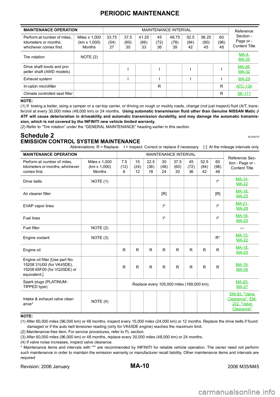
Schedule 2NLS0007D
EMISSION CONTROL SYSTEM MAINTENANCE
Abbreviations: R = Replace. I = Inspect. Correct or replace if necessary. [ ]: At the mileage intervals only
NOTE:
(1) After 60,000 miles (96,000 km) or 48 months, inspect every 15,000 miles (24,000 km) or 12 months. Replace the drive belts if found
damaged or if the auto belt tensioner reading (only for VK45DE engine) reaches the maximum limit.
(2) Maintenance-free item. For service procedures, refer to FL section.
(3) After 60,000 miles (96,000 km) or 48 months, replace every 30,000 miles (48,000 km) or 24 months.
(4) If valve noise increases, inspect valve clearance.
* Maintenance items and intervals with “*” are recommended by INFINITI for reliable vehicle operation. The owner need not perform
such maintenance in order to maintain the emission warranty or manufacturer recall liability. Other maintenance items and intervals are
required Tire rotation NOTE (2)MA-4
,
MA-35
Drive shaft boots and pro-
peller shaft (AWD models)I IIIMA-38,
MA-32
Exhaust system I I I IMA-29
In-cabin microfilter R RATC-134
Climate controlled seat filterRSE-171
MAINTENANCE OPERATIONMAINTENANCE INTERVAL
Reference
Section -
Page or -
Content Title Perform at number of miles,
kilometers or months,
whichever comes first.Miles x 1,000
(km x 1,000)
Months33.75
(54)
2737.5
(60)
3041.25
(66)
3345
(72)
3648.75
(78)
3952.5
(84)
4256.25
(90)
4560
(96)
48
MAINTENANCE OPERATIONMAINTENANCE INTERVAL
Reference Sec-
tion - Page or -
Content Title Perform at number of miles,
kilometers or months, whichever
comes first.Miles x 1,000
(km x 1,000)
Months7.5
(12)
615
(24)
1222.5
(36)
1830
(48)
2437.5
(60)
3045
(72)
3652.5
(84)
4260
(96)
48
Drive belts NOTE (1) I*MA-14
,
MA-22
Air cleaner filter [R] [R]MA-18,
MA-25
EVAP vapor lines I* I*MA-21,
MA-28
Fuel lines I* I*MA-18,
MA-25
Fuel filter NOTE (2)—
Engine coolant NOTE (3) R*MA-15
,
MA-22
Engine oil RRRRRRRRMA-18,
MA-25
Engine oil filter [Use part No.
15208 31U00 (for VK45DE),
15208 65F00 (for VQ35DE) or
equivalent.]RRRR R RRRMA-19
,
MA-26
Spark plugs (PLATINUM-
TIPPED type)Replace every 105,000 miles (169,000 km).MA-20,
MA-27
Intake & exhaust valve clear-
ance*NOTE (4)EM-93, "
Va l v e
Clearance", EM-
222, "Va l v e
Clearance"