Page 5058 of 5621

SIDE OIL SEAL
RFD-15
C
E
F
G
H
I
J
K
L
MA
B
RFD
Revision: 2006 January2006 M35/M45
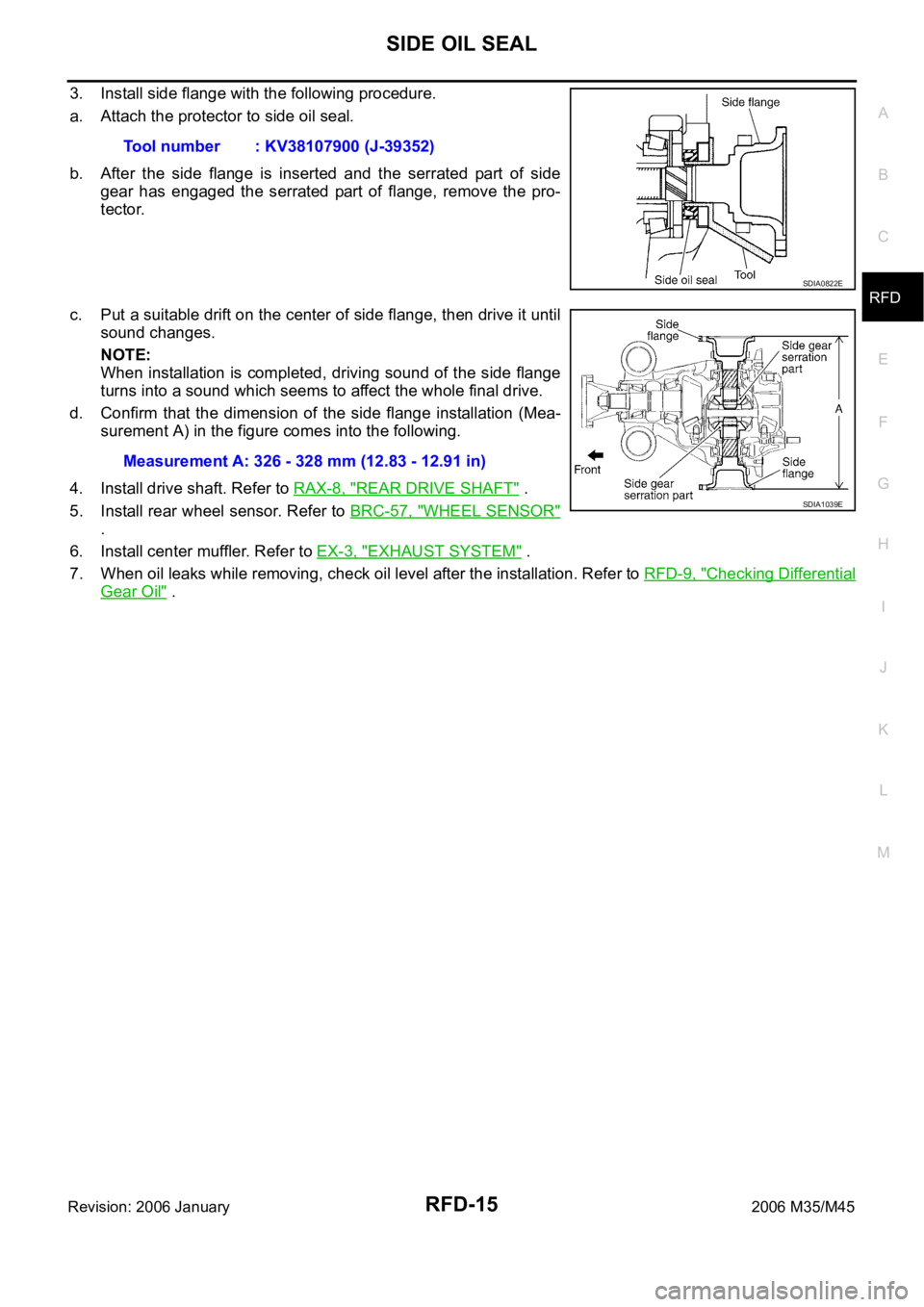
3. Install side flange with the following procedure.
a. Attach the protector to side oil seal.
b. After the side flange is inserted and the serrated part of side
gear has engaged the serrated part of flange, remove the pro-
tector.
c. Put a suitable drift on the center of side flange, then drive it until
sound changes.
NOTE:
When installation is completed, driving sound of the side flange
turns into a sound which seems to affect the whole final drive.
d. Confirm that the dimension of the side flange installation (Mea-
surement A) in the figure comes into the following.
4. Install drive shaft. Refer to RAX-8, "
REAR DRIVE SHAFT" .
5. Install rear wheel sensor. Refer to BRC-57, "
WHEEL SENSOR"
.
6. Install center muffler. Refer to EX-3, "
EXHAUST SYSTEM" .
7. When oil leaks while removing, check oil level after the installation. Refer to RFD-9, "
Checking Differential
Gear Oil" . Tool number : KV38107900 (J-39352)
SDIA0822E
Measurement A: 326 - 328 mm (12.83 - 12.91 in)
SDIA1039E
Page 5065 of 5621

RFD-22
REAR FINAL DRIVE ASSEMBLY
Revision: 2006 January2006 M35/M45
Companion Flange Runout
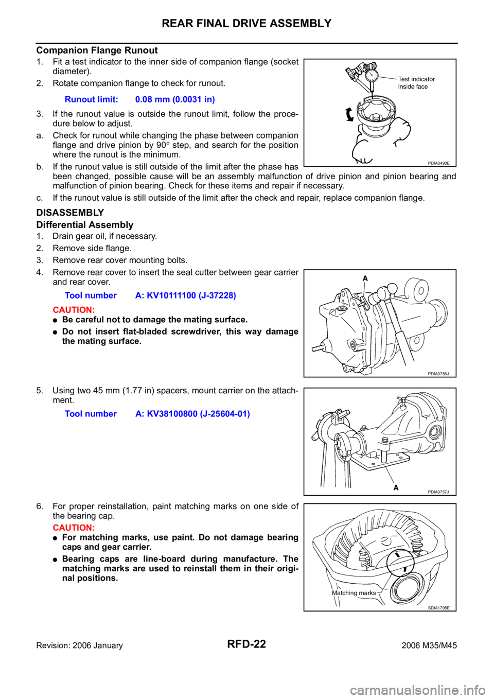
1. Fit a test indicator to the inner side of companion flange (socket
diameter).
2. Rotate companion flange to check for runout.
3. If the runout value is outside the runout limit, follow the proce-
dure below to adjust.
a. Check for runout while changing the phase between companion
flange and drive pinion by 90
step, and search for the position
where the runout is the minimum.
b. If the runout value is still outside of the limit after the phase has
been changed, possible cause will be an assembly malfunction of drive pinion and pinion bearing and
malfunction of pinion bearing. Check for these items and repair if necessary.
c. If the runout value is still outside of the limit after the check and repair, replace companion flange.
DISASSEMBLY
Differential Assembly
1. Drain gear oil, if necessary.
2. Remove side flange.
3. Remove rear cover mounting bolts.
4. Remove rear cover to insert the seal cutter between gear carrier
and rear cover.
CAUTION:
Be careful not to damage the mating surface.
Do not insert flat-bladed screwdriver, this way damage
the mating surface.
5. Using two 45 mm (1.77 in) spacers, mount carrier on the attach-
ment.
6. For proper reinstallation, paint matching marks on one side of
the bearing cap.
CAUTION:
For matching marks, use paint. Do not damage bearing
caps and gear carrier.
Bearing caps are line-board during manufacture. The
matching marks are used to reinstall them in their origi-
nal positions.Runout limit: 0.08 mm (0.0031 in)
PDIA0490E
Tool number A: KV10111100 (J-37228)
PDIA0756J
Tool number A: KV38100800 (J-25604-01)
PDIA0757J
SDIA1795E
Page 5079 of 5621

RFD-36
REAR FINAL DRIVE ASSEMBLY
Revision: 2006 January2006 M35/M45
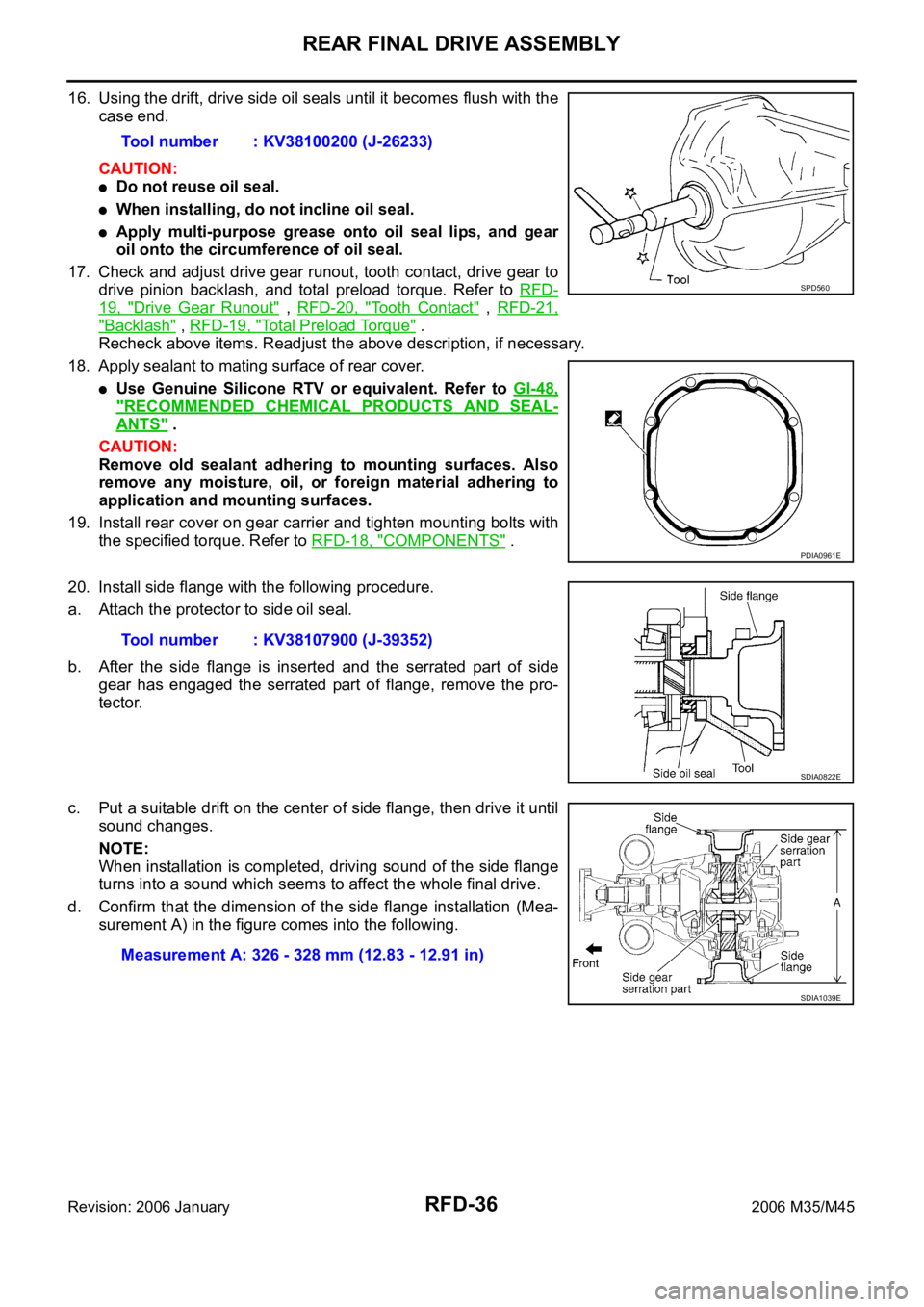
16. Using the drift, drive side oil seals until it becomes flush with the
case end.
CAUTION:
Do not reuse oil seal.
When installing, do not incline oil seal.
Apply multi-purpose grease onto oil seal lips, and gear
oil onto the circumference of oil seal.
17. Check and adjust drive gear runout, tooth contact, drive gear to
drive pinion backlash, and total preload torque. Refer to RFD-
19, "Drive Gear Runout" , RFD-20, "Tooth Contact" , RFD-21,
"Backlash" , RFD-19, "Total Preload Torque" .
Recheck above items. Readjust the above description, if necessary.
18. Apply sealant to mating surface of rear cover.
Use Genuine Silicone RTV or equivalent. Refer to GI-48,
"RECOMMENDED CHEMICAL PRODUCTS AND SEAL-
ANTS" .
CAUTION:
Remove old sealant adhering to mounting surfaces. Also
remove any moisture, oil, or foreign material adhering to
application and mounting surfaces.
19. Install rear cover on gear carrier and tighten mounting bolts with
the specified torque. Refer to RFD-18, "
COMPONENTS" .
20. Install side flange with the following procedure.
a. Attach the protector to side oil seal.
b. After the side flange is inserted and the serrated part of side
gear has engaged the serrated part of flange, remove the pro-
tector.
c. Put a suitable drift on the center of side flange, then drive it until
sound changes.
NOTE:
When installation is completed, driving sound of the side flange
turns into a sound which seems to affect the whole final drive.
d. Confirm that the dimension of the side flange installation (Mea-
surement A) in the figure comes into the following.Tool number : KV38100200 (J-26233)
SPD560
PDIA0961E
Tool number : KV38107900 (J-39352)
SDIA0822E
Measurement A: 326 - 328 mm (12.83 - 12.91 in)
SDIA1039E