2006 INFINITI M35 Motor
[x] Cancel search: MotorPage 5192 of 5621
AUTOMATIC DRIVE POSITIONER
SE-11
C
D
E
F
G
H
J
K
L
MA
B
SE
Revision: 2006 January2006 M35/M45
AUTOMATIC DRIVE POSITIONERPFP:28491
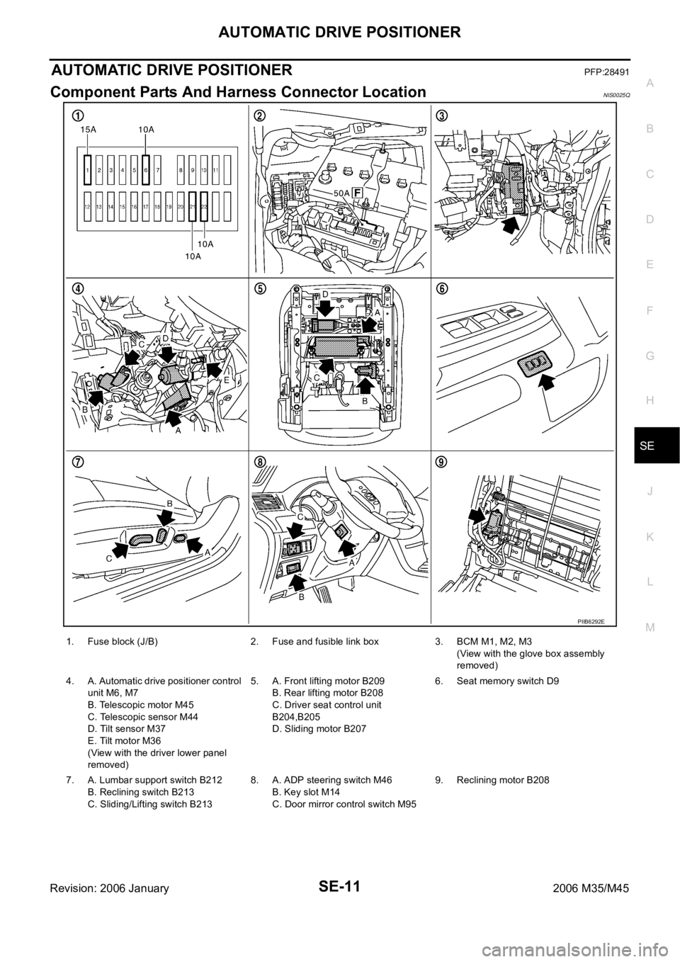
Component Parts And Harness Connector LocationNIS0025Q
PIIB6292E
1. Fuse block (J/B) 2. Fuse and fusible link box 3. BCM M1, M2, M3
(View with the glove box assembly
removed)
4. A. Automatic drive positioner control
unit M6, M7
B. Telescopic motor M45
C. Telescopic sensor M44
D. Tilt sensor M37
E. Tilt motor M36
(View with the driver lower panel
removed)5. A. Front lifting motor B209
B. Rear lifting motor B208
C. Driver seat control unit
B204,B205
D. Sliding motor B2076. Seat memory switch D9
7. A. Lumbar support switch B212
B. Reclining switch B213
C. Sliding/Lifting switch B2138. A. ADP steering switch M46
B. Key slot M14
C. Door mirror control switch M959. Reclining motor B208
Page 5212 of 5621
AUTOMATIC DRIVE POSITIONER
SE-31
C
D
E
F
G
H
J
K
L
MA
B
SE
Revision: 2006 January2006 M35/M45
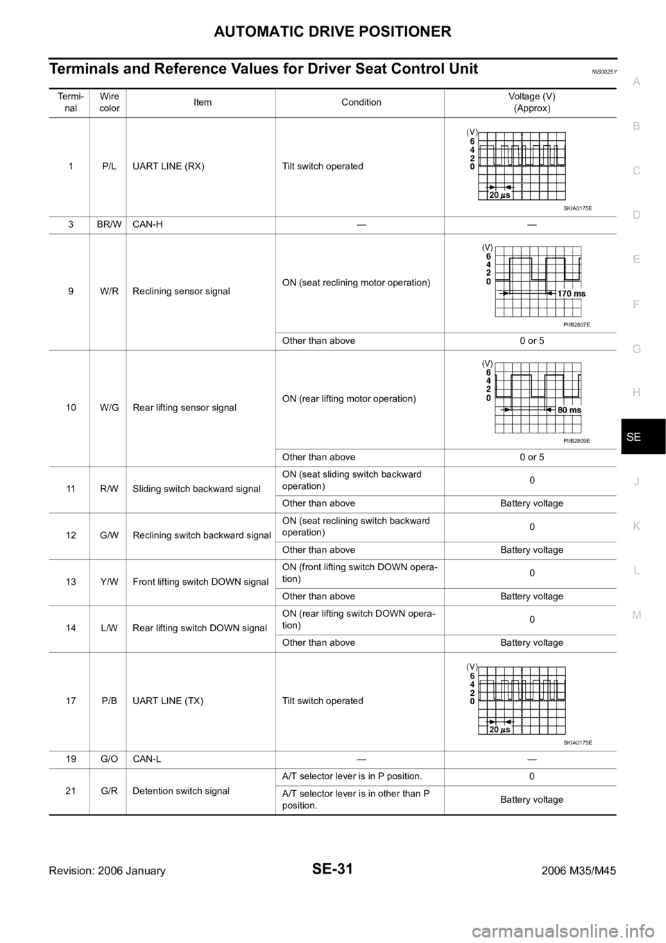
Terminals and Reference Values for Driver Seat Control UnitNIS0025Y
Te r m i -
nalWire
colorItem ConditionVoltage (V)
(Approx)
1 P/L UART LINE (RX) Tilt switch operated
3BR/WCAN-H — —
9 W/R Reclining sensor signalON (seat reclining motor operation)
Other than above 0 or 5
10 W/G Rear lifting sensor signalON (rear lifting motor operation)
Other than above 0 or 5
11 R/W Sliding switch backward signalON (seat sliding switch backward
operation)0
Other than above Battery voltage
12 G/W Reclining switch backward signalON (seat reclining switch backward
operation)0
Other than above Battery voltage
13 Y/W Front lifting switch DOWN signalON (front lifting switch DOWN opera-
tion)0
Other than above Battery voltage
14 L/W Rear lifting switch DOWN signalON (rear lifting switch DOWN opera-
tion)0
Other than above Battery voltage
17 P/B UART LINE (TX) Tilt switch operated
19 G/O CAN-L — —
21 G/R Detention switch signalA/T selector lever is in P position. 0
A/T selector lever is in other than P
position.Battery voltage
SKIA0175E
PIIB2807E
PIIB2809E
SKIA0175E
Page 5213 of 5621
SE-32
AUTOMATIC DRIVE POSITIONER
Revision: 2006 January2006 M35/M45
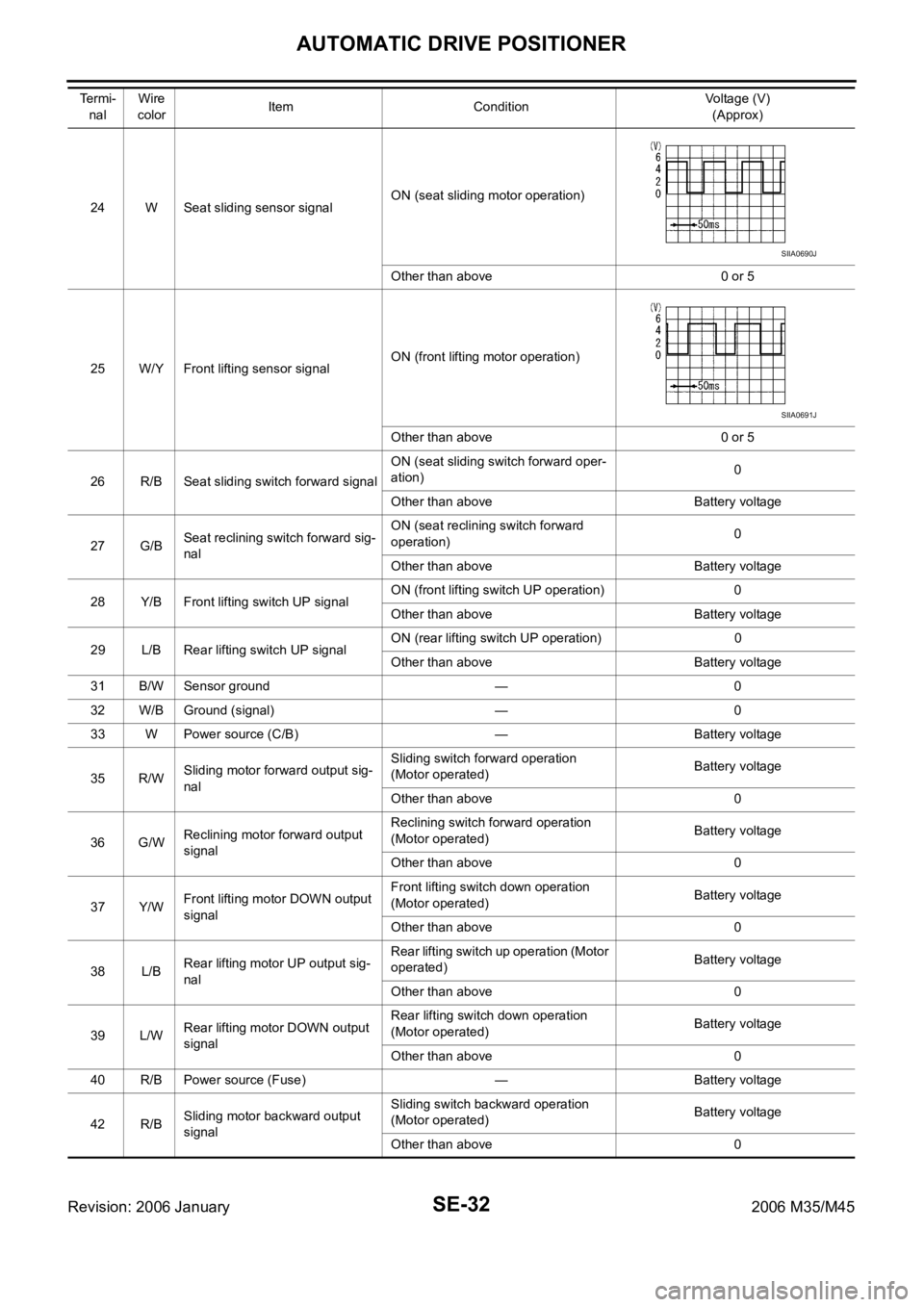
24 W Seat sliding sensor signalON (seat sliding motor operation)
Other than above 0 or 5
25 W/Y Front lifting sensor signalON (front lifting motor operation)
Other than above 0 or 5
26 R/B Seat sliding switch forward signalON (seat sliding switch forward oper-
ation)0
Other than above Battery voltage
27 G/BSeat reclining switch forward sig-
nalON (seat reclining switch forward
operation)0
Other than above Battery voltage
28 Y/B Front lifting switch UP signalON (front lifting switch UP operation) 0
Other than above Battery voltage
29 L/B Rear lifting switch UP signalON (rear lifting switch UP operation) 0
Other than above Battery voltage
31 B/W Sensor ground — 0
32 W/B Ground (signal) — 0
33 W Power source (C/B) — Battery voltage
35 R/WSliding motor forward output sig-
nalSliding switch forward operation
(Motor operated)Battery voltage
Other than above 0
36 G/WReclining motor forward output
signalReclining switch forward operation
(Motor operated)Battery voltage
Other than above 0
37 Y/WFront lifting motor DOWN output
signalFront lifting switch down operation
(Motor operated)Battery voltage
Other than above 0
38 L/BRear lifting motor UP output sig-
nalRear lifting switch up operation (Motor
operated)Battery voltage
Other than above 0
39 L/WRear lifting motor DOWN output
signalRear lifting switch down operation
(Motor operated)Battery voltage
Other than above 0
40 R/B Power source (Fuse) — Battery voltage
42 R/BSliding motor backward output
signalSliding switch backward operation
(Motor operated)Battery voltage
Other than above 0 Te r m i -
nalWire
colorItem ConditionVoltage (V)
(Approx)
SIIA0690J
SIIA0691J
Page 5214 of 5621
AUTOMATIC DRIVE POSITIONER
SE-33
C
D
E
F
G
H
J
K
L
MA
B
SE
Revision: 2006 January2006 M35/M45
Terminals and Reference Values for Automatic Drive Positioner Control UnitNIS0025Z
44 G/BReclining motor backward output
signalReclining switch backward operation
(Motor operated)Battery voltage
Other than above 0
45 Y/BFront lifting motor UP output sig-
nalFront lifting switch upward operation
(Motor operated)Battery voltage
Other than above 0
48 B Ground (power) — 0 Te r m i -
nalWire
colorItem ConditionVoltage (V)
(Approx)
Te r m i -
nal Wire
colorItem ConditionVoltage (V)
(Approx)
1 Y Tilt switch UP signalTilt switch is UP operation 0
Other than above 5
5L/RMirror sensor (RH vertical)
signalWhen mirror motor RH is UP or DOWN
operationChanges between 4.2 (close to perk)
0.5 (close to valley)
6LGMirror sensor (LH vertical)
signalWhen mirror motor LH is UP or DOWN
operationChanges between 4.2 (close to perk)
0.5 (close to valley)
7 L Tilt sensor signalTilt position : Top 1
Tilt position : Bottom 3.8
9 LG Memory switch 1 signalMemory switch 1 ON 0
Other than above 5
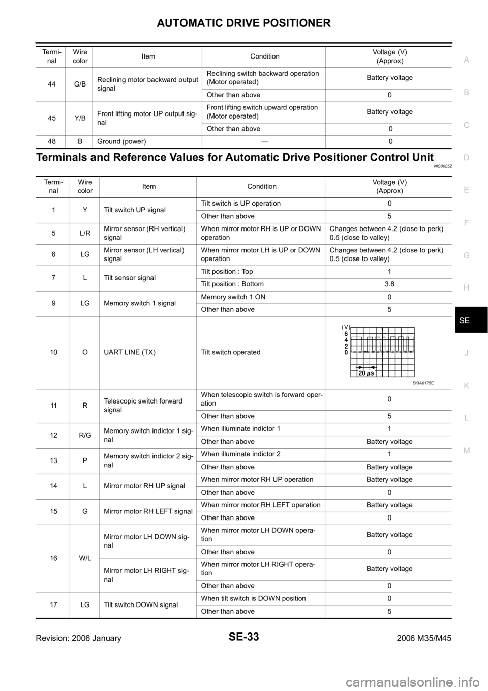
10 O UART LINE (TX) Tilt switch operated
11 RTelescopic switch forward
signalWhen telescopic switch is forward oper-
ation0
Other than above 5
12 R/GMemory switch indictor 1 sig-
nalWhen illuminate indictor 1 1
Other than above Battery voltage
13 PMemory switch indictor 2 sig-
nalWhen illuminate indictor 2 1
Other than above Battery voltage
14 L Mirror motor RH UP signalWhen mirror motor RH UP operation Battery voltage
Other than above 0
15 G Mirror motor RH LEFT signalWhen mirror motor RH LEFT operation Battery voltage
Other than above 0
16 W/LMirror motor LH DOWN sig-
nalWhen mirror motor LH DOWN opera-
tionBattery voltage
Other than above 0
Mirror motor LH RIGHT sig-
nalWhen mirror motor LH RIGHT opera-
tionBattery voltage
Other than above 0
17 LG Tilt switch DOWN signalWhen tilt switch is DOWN position 0
Other than above 5
SKIA0175E
Page 5215 of 5621
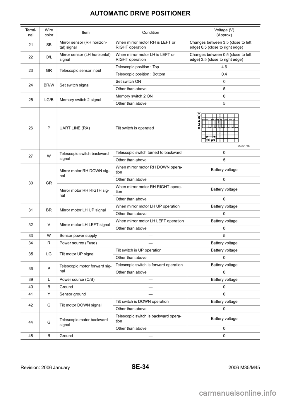
SE-34
AUTOMATIC DRIVE POSITIONER
Revision: 2006 January2006 M35/M45
21 SBMirror sensor (RH horizon-
tal) signalWhen mirror motor RH is LEFT or
RIGHT operationChanges between 3.5 (close to left
edge) 0.5 (close to right edge)
22 O/LMirror sensor (LH horizontal)
signalWhen mirror motor LH is LEFT or
RIGHT operationChanges between 0.5 (close to left
edge) 3.5 (close to right edge)
23 GR Telescopic sensor inputTelescopic position : Top 4.6
Telescopic position : Bottom 0.4
24 BR/W Set switch signalSet switch ON 0
Other than above 5
25 LG/B Memory switch 2 signalMemory switch 2 ON 0
Other than above 5
26 P UART LINE (RX) Tilt switch is operated
27 WTelescopic switch backward
signalTelescopic switch turned to backward 0
Other than above 5
30 GRMirror motor RH DOWN sig-
nalWhen mirror motor RH DOWN opera-
tionBattery voltage
Other than above 0
Mirror motor RH RIGTH sig-
nalWhen mirror motor RH RIGHT opera-
tionBattery voltage
Other than above 0
31 BR Mirror motor LH UP signalWhen mirror motor LH UP operation Battery voltage
Other than above 0
32 V Mirror motor LH LEFT signalWhen mirror motor LH LEFT operation Battery voltage
Other than above 0
33 W Sensor power supply — 5
34 R Power source (Fuse) — Battery voltage
35 LG Tilt motor UP signalTilt switch is UP operation Battery voltage
Other than above 0
36 PTelescopic motor forward sig-
nalTelescopic switch is forward operation Battery voltage
Other than above 0
39 L Power source (C/B) — Battery voltage
40 B Ground — 0
41 Y Sensor ground — 0
42 G Tilt motor DOWN signalTilt switch is DOWN operation Battery voltage
Other than above 0
44 GTelescopic motor backward
signalTelescopic switch is backward opera-
tionBattery voltage
Other than above 0
48 B Ground — 0 Termi-
nal Wire
colorItem ConditionVoltage (V)
(Approx)
SKIA0175E
Page 5217 of 5621
SE-36
AUTOMATIC DRIVE POSITIONER
Revision: 2006 January2006 M35/M45
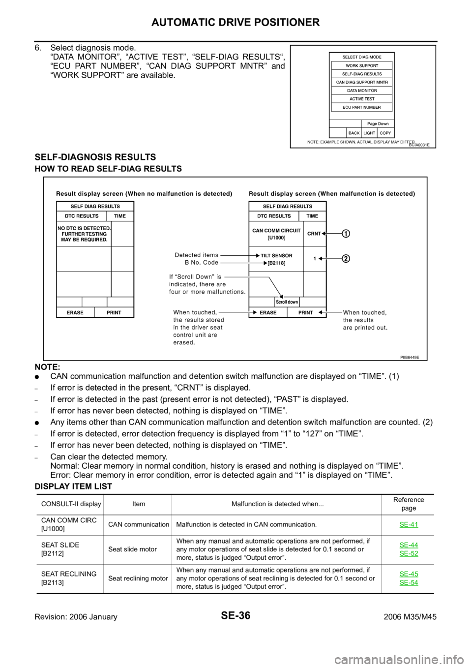
6. Select diagnosis mode.
“DATA MONITOR”, “ACTIVE TEST”, “SELF-DIAG RESULTS“,
“ECU PART NUMBER”, “CAN DIAG SUPPORT MNTR” and
“WORK SUPPORT” are available.
SELF-DIAGNOSIS RESULTS
HOW TO READ SELF-DIAG RESULTS
NOTE:
CAN communication malfunction and detention switch malfunction are displayed on “TIME”. (1)
–If error is detected in the present, “CRNT” is displayed.
–If error is detected in the past (present error is not detected), “PAST” is displayed.
–If error has never been detected, nothing is displayed on “TIME”.
Any items other than CAN communication malfunction and detention switch malfunction are counted. (2)
–If error is detected, error detection frequency is displayed from “1” to “127” on “TIME”.
–If error has never been detected, nothing is displayed on “TIME”.
–Can clear the detected memory.
Normal: Clear memory in normal condition, history is erased and nothing is displayed on “TIME”.
Error: Clear memory in error condition, error is detected again and “1” is displayed on “TIME”.
DISPLAY ITEM LIST
BCIA0031E
CONSULT-II display Item Malfunction is detected when...Reference
page
CAN COMM CIRC
[U1000]CAN communication Malfunction is detected in CAN communication.SE-41
SEAT SLIDE
[B2112]Seat slide motorWhen any manual and automatic operations are not performed, if
any motor operations of seat slide is detected for 0.1 second or
more, status is judged “Output error”.SE-44
SE-52
SEAT RECLINING
[B2113]Seat reclining motorWhen any manual and automatic operations are not performed, if
any motor operations of seat reclining is detected for 0.1 second or
more, status is judged “Output error”.SE-45
SE-54
PIIB6449E
Page 5218 of 5621
![INFINITI M35 2006 Factory Service Manual AUTOMATIC DRIVE POSITIONER
SE-37
C
D
E
F
G
H
J
K
L
MA
B
SE
Revision: 2006 January2006 M35/M45
DATA MONITOR
SELECTIOM FROM MEMU
SEAT LIFTER FR
[B2114]Seat lifting FR motorWhen any manual and automatic INFINITI M35 2006 Factory Service Manual AUTOMATIC DRIVE POSITIONER
SE-37
C
D
E
F
G
H
J
K
L
MA
B
SE
Revision: 2006 January2006 M35/M45
DATA MONITOR
SELECTIOM FROM MEMU
SEAT LIFTER FR
[B2114]Seat lifting FR motorWhen any manual and automatic](/manual-img/42/57023/w960_57023-5217.png)
AUTOMATIC DRIVE POSITIONER
SE-37
C
D
E
F
G
H
J
K
L
MA
B
SE
Revision: 2006 January2006 M35/M45
DATA MONITOR
SELECTIOM FROM MEMU
SEAT LIFTER FR
[B2114]Seat lifting FR motorWhen any manual and automatic operations are not performed, if
any motor operations of seat lifting FR is detected for 0.1 second or
more, status is judged “Output error”.SE-46
SE-56
SEAT LIFTER RR
[B2115]Seat lifting RR motorWhen any manual and automatic operations are not performed, if
any motor operations of seat lifting RR is detected for 0.1 second or
more, status is judged “Output error”.SE-48
SE-58
TILT OUTPUT
[B2116]Tilt motorWhen any manual and automatic operations are not performed, if
any motor operations of seat tilt is detected for 0.1 second or more,
status is judged “Output error”.SE-50
TILT SENSOR
[B2118]Tilt sensorWhen driver seat control unit detects 0.1V or lower, or 4.9V or higher,
from tilt sensor for 0.5 seconds or more.SE-62
TELESCO SEN-
SOR
[B2119]Telescopic sensorWhen driver seat control unit detects 0.1V or lower, or 4.9V or higher,
from telescopic sensor for 0.5 seconds or more.SE-60
DETENT SW
[B2126]Detention SWWith the A/T selector lever in P position (Detente switch OFF), if the
vehicle speed of 7 km/h (4 MPH) or higher was input the detention
switch input system is judged malfunctioning.SE-85
UART COMM
[B2128]UART communica-
tionMalfunction is detected in UART communication.SE-87
CONSULT-II display Item Malfunction is detected when...Reference
page
Monitor item [OPERATION or UNIT] Contents
SET SW “ON/OFF” ON/OFF status judged from the setting switch signal is displayed.
MEMORY SW1 “ON/OFF” ON/OFF status judged from the seat memory switch 1 signal is displayed.
MEMORY SW2 “ON/OFF” ON/OFF status judged from the seat memory switch 2 signal is displayed.
SLIDE SW–FR “ON/OFF” ON/OFF status judged from the sliding switch (FR) signal is displayed.
SLIDE SW–RR “ON/OFF” ON/OFF status judged from the sliding switch (RR) signal is displayed.
RECLN SW–FR “ON/OFF” ON/OFF status judged from the reclining switch (FR) signal is displayed.
RECLN SW–RR “ON/OFF” ON/OFF status judged from the reclining switch (RR) signal is displayed.
LIFT FR SW–UP “ON/OFF” ON/OFF status judged from the FR lifting switch (UP) signal is displayed.
LIFT FR SW–DN “ON/OFF” ON/OFF status judged from the FR lifting switch (DOWN) signal is displayed.
LIFT RR SW–UP “ON/OFF” ON/OFF status judged from the RR lifting switch (UP) signal is displayed.
LIFT RR SW–DN “ON/OFF” ON/OFF status judged from the RR lifting switch (DOWN) signal is displayed.
MIR CON SW–UP “ON/OFF”ON/OFF status judged from the door mirror remote control switch (UP) signal is
displayed.
MIR CON SW–DN “ON/OFF”ON/OFF status judged from the door mirror remote control switch (DOWN) signal
is displayed.
MIR CON SW–RH “ON/OFF”ON/OFF status judged from the door mirror remote control switch (RIGHT) signal
is displayed.
MIR CON SW–LH “ON/OFF”ON/OFF status judged from the door mirror remote control switch (LEFT) signal is
displayed.
MIR CHNG SW–R “ON/OFF”ON/OFF status judged from the door mirror remote control switch (switching to
RIGHT) signal is displayed.
MIR CHNG SW–L “ON/OFF”ON/OFF status judged from the door mirror remote control switch (switching to
LEFT) signal is displayed.
TILT SW-UP “ON/OFF” ON/OFF status judged from the tilt switch (UP) signal is displayed.
TILT SW-DOWN “ON/OFF” ON/OFF status judged from the tilt switch (DOWN) signal is displayed.
TELESCO SW-FR “ON/OFF” ON/OFF status judged from the telescoping switch (FR) signal is displayed.
TELESCO SW-RR “ON/OFF” ON/OFF status judged from the telescoping switch (RR) signal is displayed.
Page 5219 of 5621
SE-38
AUTOMATIC DRIVE POSITIONER
Revision: 2006 January2006 M35/M45
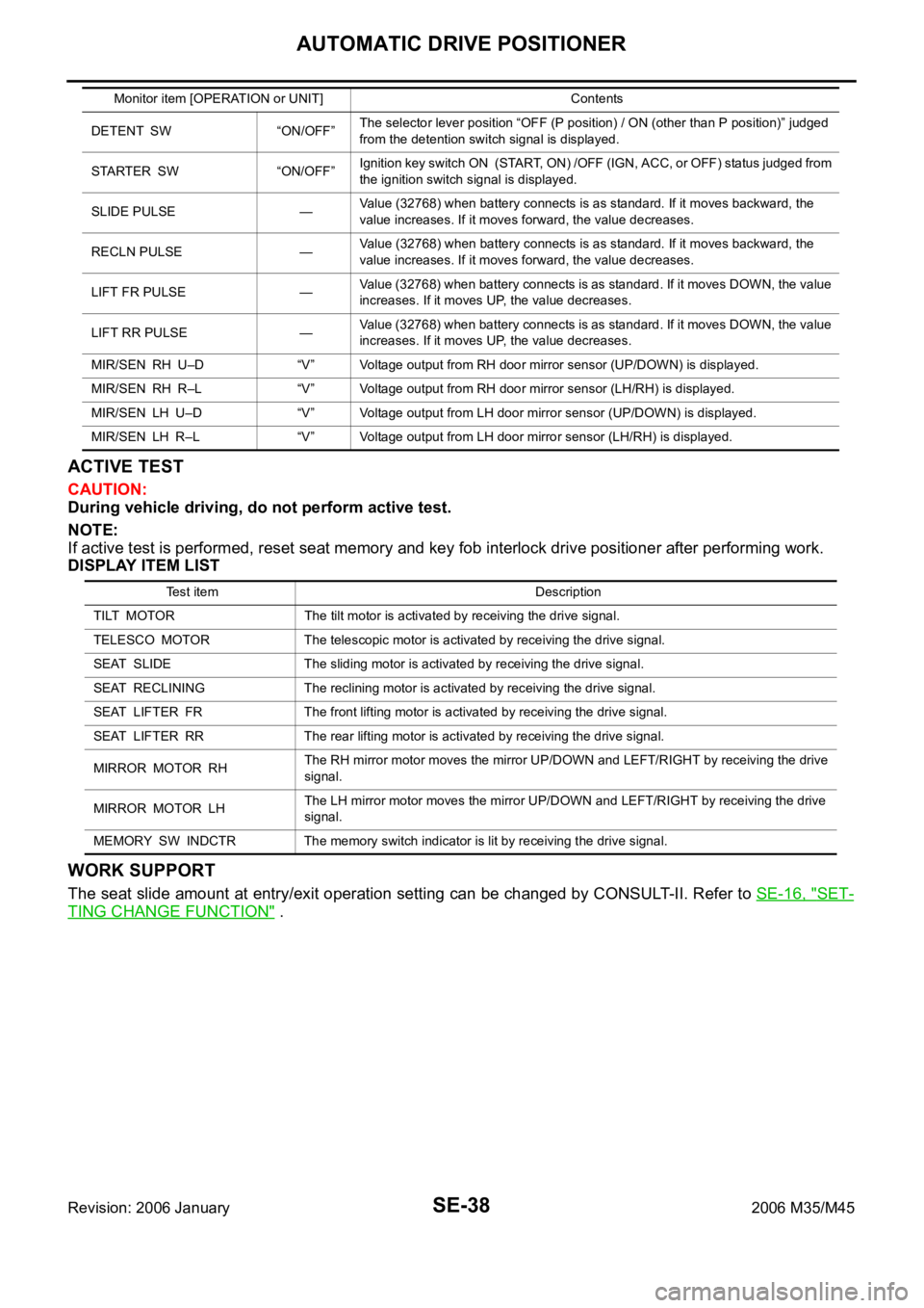
ACTIVE TEST
CAUTION:
During vehicle driving, do not perform active test.
NOTE:
If active test is performed, reset seat memory and key fob interlock drive positioner after performing work.
DISPLAY ITEM LIST
WORK SUPPORT
The seat slide amount at entry/exit operation setting can be changed by CONSULT-II. Refer to SE-16, "SET-
TING CHANGE FUNCTION" .
DETENT SW “ON/OFF”The selector lever position “OFF (P position) / ON (other than P position)” judged
from the detention switch signal is displayed.
STARTER SW “ON/OFF”Ignition key switch ON (START, ON) /OFF (IGN, ACC, or OFF) status judged from
the ignition switch signal is displayed.
SLIDE PULSE —Value (32768) when battery connects is as standard. If it moves backward, the
value increases. If it moves forward, the value decreases.
RECLN PULSE —Value (32768) when battery connects is as standard. If it moves backward, the
value increases. If it moves forward, the value decreases.
LIFT FR PULSE —Value (32768) when battery connects is as standard. If it moves DOWN, the value
increases. If it moves UP, the value decreases.
LIFT RR PULSE —Value (32768) when battery connects is as standard. If it moves DOWN, the value
increases. If it moves UP, the value decreases.
MIR/SEN RH U–D “V” Voltage output from RH door mirror sensor (UP/DOWN) is displayed.
MIR/SEN RH R–L “V” Voltage output from RH door mirror sensor (LH/RH) is displayed.
MIR/SEN LH U–D “V” Voltage output from LH door mirror sensor (UP/DOWN) is displayed.
MIR/SEN LH R–L “V” Voltage output from LH door mirror sensor (LH/RH) is displayed. Monitor item [OPERATION or UNIT] Contents
Test item Description
TILT MOTOR The tilt motor is activated by receiving the drive signal.
TELESCO MOTOR The telescopic motor is activated by receiving the drive signal.
SEAT SLIDE The sliding motor is activated by receiving the drive signal.
SEAT RECLINING The reclining motor is activated by receiving the drive signal.
SEAT LIFTER FR The front lifting motor is activated by receiving the drive signal.
SEAT LIFTER RR The rear lifting motor is activated by receiving the drive signal.
MIRROR MOTOR RHThe RH mirror motor moves the mirror UP/DOWN and LEFT/RIGHT by receiving the drive
signal.
MIRROR MOTOR LHThe LH mirror motor moves the mirror UP/DOWN and LEFT/RIGHT by receiving the drive
signal.
MEMORY SW INDCTR The memory switch indicator is lit by receiving the drive signal.