2006 INFINITI M35 Motor
[x] Cancel search: MotorPage 5014 of 5621

RF-1
ROOF
I BODY
CONTENTS
C
D
E
F
G
H
J
K
L
M
SECTION RF
A
B
RF
Revision: 2006 January2006 M35/M45
ROOF
PRECAUTIONS .......................................................... 2
Precautions for Supplemental Restraint System
(SRS) “AIR BAG” and “SEAT BELT PRE-TEN-
SIONER” .................................................................. 2
Precautions .............................................................. 2
PREPARATION ........................................................... 3
Special Service Tools ............................................... 3
Commercial Service Tools ........................................ 3
SQUEAK AND RATTLE TROUBLE DIAGNOSES ..... 4
Work Flow ................................................................ 4
CUSTOMER INTERVIEW ..................................... 4
DUPLICATE THE NOISE AND TEST DRIVE ....... 5
CHECK RELATED SERVICE BULLETINS ........... 5
LOCATE THE NOISE AND IDENTIFY THE
ROOT CAUSE ...................................................... 5
REPAIR THE CAUSE ........................................... 5
CONFIRM THE REPAIR ....................................... 6
Generic Squeak and Rattle Troubleshooting ........... 6
INSTRUMENT PANEL .......................................... 6
CENTER CONSOLE ............................................. 6
DOORS ................................................................. 6
TRUNK .................................................................. 7
SUNROOF/HEADLINING ..................................... 7
SEATS ................................................................... 7
UNDERHOOD ....................................................... 7
Diagnostic Worksheet .............................................. 8
SUNROOF ................................................................ 10
Component Parts and Harness Connector Location ... 10
System Description ................................................. 11
TILT UP / SLIDE CLOSE OPERATION ................ 11TILT DOWN / SLIDE OPEN OPERATION .......... 11
AUTO OPERATION ............................................. 11
RETAINED POWER OPERATION ...................... 11
ANTI-PINCH FUNCTION .................................... 12
INITIALIZATION PROCEDURE .......................... 12
Wiring Diagram — SROOF — ................................ 13
Terminals and Reference Value for BCM ............... 15
Terminals and Reference Value for Sunroof Motor
Assembly ................................................................ 15
CONSULT-II Function (BCM) ................................. 16
ACTIVE TEST ..................................................... 17
WORK SUPPORT ............................................... 17
DATE MONITOR ................................................. 17
Work Flow ............................................................... 18
Diagnosis Symptom Chart ...................................... 18
BCM Power Supply and Ground Circuit Check ...... 18
Sunroof Motor Assembly Power Supply and Ground
Circuit Check .......................................................... 19
Sunroof Switch Check .........................................
... 21
Door Switch Check ..............................................
... 23
Fitting Adjustment ................................................... 25
RID WEATHERSTRIP OVERLAP ADJUST-
MENT AND SURFACE MISMATCH ADJUST-
MENT .................................................................. 25
Removal and Installation ........................................ 25
SUNROOF UNIT ................................................. 27
Disassembly and Assembly .................................... 28
DISASSEMBLY ................................................... 29
ASSEMBLY ......................................................... 29
Page 5023 of 5621

RF-10
SUNROOF
Revision: 2006 January2006 M35/M45
SUNROOFPFP:91210
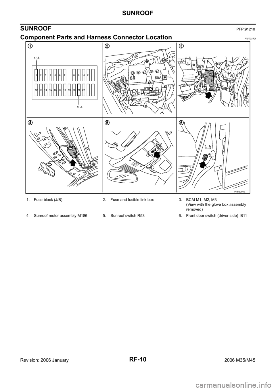
Component Parts and Harness Connector LocationNIS0023Q
PIIB6291E
1. Fuse block (J/B) 2. Fuse and fusible link box 3. BCM M1, M2, M3
(View with the glove box assembly
removed)
4. Sunroof motor assembly M186 5. Sunroof switch R53 6. Front door switch (driver side) B11
Page 5024 of 5621

SUNROOF
RF-11
C
D
E
F
G
H
J
K
L
MA
B
RF
Revision: 2006 January2006 M35/M45
System DescriptionNIS0023R
Power supplied at all time
through 50A fusible link (letter F , located in the fuse and fusible link box)
to BCM terminal 55.
through 10A fuse [No.21, located in the fuse block (J/B)]
to BCM terminal 42.
through BCM terminal 54
to sunroof motor assembly terminal 1.
When ignition switch ON or START position,
Power is supplied
through 15A fuse [No.1, located in the fuse block (J/B)]
to BCM terminal 38.
through BCM terminal 53
to sunroof motor assembly terminal 6.
Ground is supplied
to BCM terminal 52
through body grounds M16 and M70.
to sunroof motor assembly terminal 8
through body ground M16 and M70.
TILT UP / SLIDE CLOSE OPERATION
When tilt up / slide close switch is pressed,
Ground is supplied
to sunroof motor assembly terminal 11
through sunroof switch terminal 3
through sunroof switch terminal 2
through sunroof motor assembly terminal 9.
Then, the sunroof tilt up / slide close.
TILT DOWN / SLIDE OPEN OPERATION
When tilt down / slide open switch is pressed,
Ground is supplied
to sunroof motor assembly terminal 4
through sunroof switch terminal 1
through sunroof switch terminal 2
through sunroof motor assembly terminal 9.
Then, the sunroof tilt down / slide open.
AUTO OPERATION
The power sunroof AUTO feature makes it possible to slide open and slide close or tilt up and tilt down the
sunroof without holding the sunroof switch in the SLIDE OPEN/TILT DOWN or SLIDE CLOSE/TILT UP posi-
tion.
RETAINED POWER OPERATION
When the ignition switch is turned to OFF position from ON position, power is supplied for 45 seconds.
through BCM terminal 53.
to sunroof motor assembly terminal 6.
When power is supplied, the sunroof can be operated.
The retained power operation is canceled when the driver or passenger side door is opened.
RAP signal period can be changed by CONSULT-II. Refer to RF-16, "
CONSULT-II Function (BCM)" .
Page 5025 of 5621

RF-12
SUNROOF
Revision: 2006 January2006 M35/M45
ANTI-PINCH FUNCTION
The CPU of sunroof motor assembly monitors the sunroof motor operation and the sunroof position (fully-
closed or other) by the signals from sunroof motor.
When sunroof motor detects an interruption during the following slide close and tilt down operation, sunroof
motor assembly controls the motor until full up position (when tilt down operate) or 125 mm (4.92 in) or more to
open direction (when slide close operate).
The function is operated in the following conditions.
close operation and tilt down when ignition switch is in the ON position.
close operation and tilt down during retained power operation.
INITIALIZATION PROCEDURE
If the battery is disconnected, the sunroof motor connector is disconnected sunroof does not close or open
automatically, use the following procedure to return sunroof operation to normal.
1. Close the sunroof if it is not in the closed position. It may be necessary to repeatedly push the switch to
close the sunroof.
2. Press the SLIDE OPEH/TILT DOWN switch for approximately 1 second or more.
3. Initialization procedure is completed. Confirm proper operation of the sunroof (slide open, slide close, tilt
up, tilt down.)
Page 5028 of 5621

SUNROOF
RF-15
C
D
E
F
G
H
J
K
L
MA
B
RF
Revision: 2006 January2006 M35/M45
Terminals and Reference Value for BCMNIS0023T
Terminals and Reference Value for Sunroof Motor AssemblyNIS0023U
Te r m i -
nalWire
colorItem ConditionVoltage (V)
(Approx.)
12 P Front door switch (passenger side)OPEN (ON) 0
CLOSE (OFF) Battery voltage
38 W Power source (IGN) Ignition switch (ON or START) position Battery voltage
42 P Power source (Fuse) — Battery voltage
52 B Ground (power) — 0
53 BR RAP signalIgnition switch ON Battery voltage
Within 45 seconds after ignition switch is turned to
OFF positionBattery voltage
When driver side or passenger side door is opened
during retained power operation.0
54 O Power window power supply (BAT) — Battery voltage
55 W Power source (Fusible link) — Battery voltage
62 V Front door switch (driver side)OPEN (ON) 0
CLOSE (OFF) Battery voltage
Te r m i -
nalWire
colorItem ConditionVoltage (V)
(Approx.)
1 O BAT power supply (BCM) — Battery voltage
4LGSunroof (TILT DOWN/SLIDE
OPEN) switch signalIgnition switch ON and sunroof switch in
TILT DOWN / SLIDE OPEN position0
Other than above Battery voltage
6YRAP signalIgnition switch ON Battery voltage
Within 45 seconds after ignition switch is turned to
OFF positionBattery voltage
When driver side or passenger side door is opened
during retained power operation.0
8 B Ground — 0
9 Y Sunroof switch ground — 0
11 LSunroof (TILT UP/SLIDE CLOSE)
switch signalIgnition switch ON and sunroof switch in
TILT UP / SLIDE CLOSE position0
Other than above Battery voltage
Page 5031 of 5621

RF-18
SUNROOF
Revision: 2006 January2006 M35/M45
Work FlowNIS0023W
1. Check the symptom and customer's requests.
2. Understand the outline of system. Refer to RF-11, "
System Description" .
3. According to the trouble diagnosis chart, repair or replace the cause of the malfunction. Refer to RF-18,
"Diagnosis Symptom Chart" .
4. Does sunroof system operate normally? If Yes, GO TO 5. If No, GO TO 3.
5. INSPECTION END.
Diagnosis Symptom ChartNIS0023X
BCM Power Supply and Ground Circuit CheckNIS0023Y
1. CHECK FUSE
Check 50A fusible link (letter F, located in the fuse and fusible link box).
Check 15A fuse [No.1, located in the fuse block (J/B)]
Check 10A fuse [No.21, located in the fuse block (J/B)]
NOTE:
Refer to RF-10, "
Component Parts and Harness Connector Location" .
OK or NG
OK >> GO TO 2.
NG >> If fuse is blown out, be sure to eliminate cause of malfunction before installing new fuse. Refer to
PG-3, "
POWER SUPPLY ROUTING CIRCUIT" .
Symptom Diagnostic procedure and repair order Refer to page
Sunroof does not operate properly.1. Power supply and ground circuit check of BCMRF-18
2. Sunroof motor assembly power supply and ground
circuit checkRF-19
3. Sunroof switch system checkRF-21
4. Replace sunroof motor assembly.RF-25
Automatic operation dose not operate.1. Initialization procedure check.RF-122. Replace sunroof motor assembly.RF-25
Motor does not stop at sunroof fully -open or fully- closed
position.1. Initialization procedure check.RF-12
2. Replace sunroof motor assembly.RF-25
Retained power operation does not operate properly.1. Check the retained power operation mode setting.RF-172. Door switch check.RF-23
3. Replace sunroof motor assembly.RF-25
Sunroof does not operate anti-pinch function.1. Initialization procedure check.RF-122. Replace sunroof motor assembly.RF-25
Page 5032 of 5621

SUNROOF
RF-19
C
D
E
F
G
H
J
K
L
MA
B
RF
Revision: 2006 January2006 M35/M45
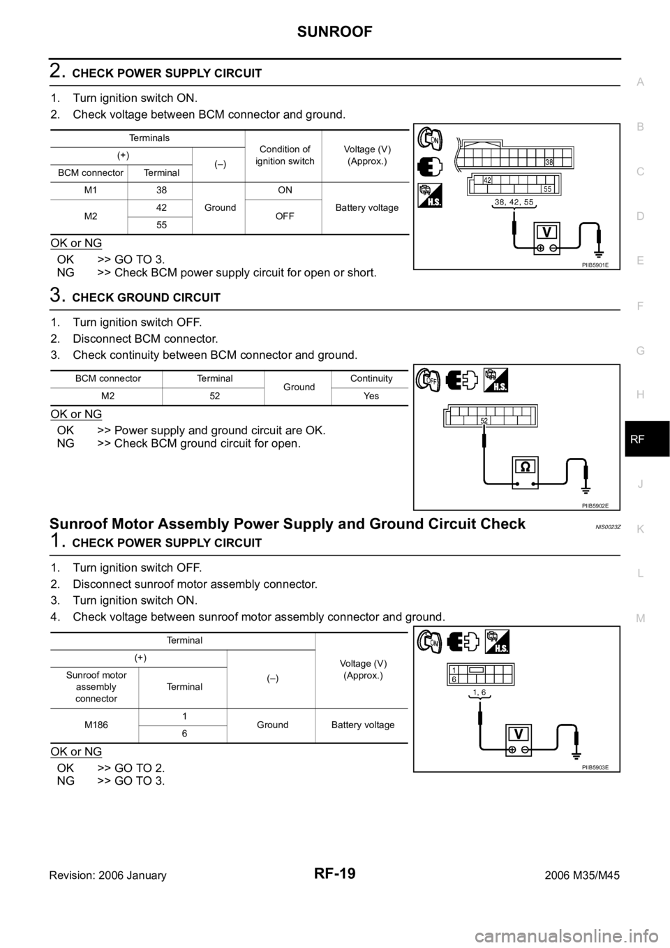
2. CHECK POWER SUPPLY CIRCUIT
1. Turn ignition switch ON.
2. Check voltage between BCM connector and ground.
OK or NG
OK >> GO TO 3.
NG >> Check BCM power supply circuit for open or short.
3. CHECK GROUND CIRCUIT
1. Turn ignition switch OFF.
2. Disconnect BCM connector.
3. Check continuity between BCM connector and ground.
OK or NG
OK >> Power supply and ground circuit are OK.
NG >> Check BCM ground circuit for open.
Sunroof Motor Assembly Power Supply and Ground Circuit CheckNIS0023Z
1. CHECK POWER SUPPLY CIRCUIT
1. Turn ignition switch OFF.
2. Disconnect sunroof motor assembly connector.
3. Turn ignition switch ON.
4. Check voltage between sunroof motor assembly connector and ground.
OK or NG
OK >> GO TO 2.
NG >> GO TO 3.
Terminals
Condition of
ignition switchVoltage (V)
(Approx.) (+)
(–)
BCM connector Terminal
M1 38
GroundON
Battery voltage
M242
OFF
55
PIIB5901E
BCM connector Terminal
GroundContinuity
M2 52 Yes
PIIB5902E
Terminal
Voltage (V)
(Approx.) (+)
(–) Sunroof motor
assembly
connectorTerminal
M1861
Ground Battery voltage
6
PIIB5903E
Page 5033 of 5621

RF-20
SUNROOF
Revision: 2006 January2006 M35/M45
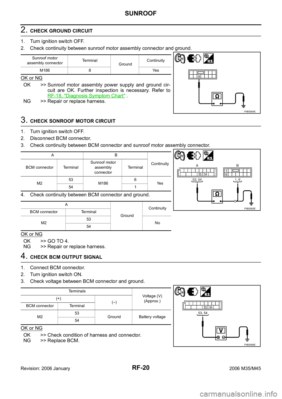
2. CHECK GROUND CIRCUIT
1. Turn ignition switch OFF.
2. Check continuity between sunroof motor assembly connector and ground.
OK or NG
OK >> Sunroof motor assembly power supply and ground cir-
cuit are OK. Further inspection is necessary. Refer to
RF-18, "
Diagnosis Symptom Chart" .
NG >> Repair or replace harness.
3. CHECK SONROOF MOTOR CIRCUIT
1. Turn ignition switch OFF.
2. Disconnect BCM connector.
3. Check continuity between BCM connector and sunroof motor assembly connector.
4. Check continuity between BCM connector and ground.
OK or NG
OK >> GO TO 4.
NG >> Repair or replace harness.
4. CHECK BCM OUTPUT SIGNAL
1. Connect BCM connector.
2. Turn ignition switch ON.
3. Check voltage between BCM connector and ground.
OK or NG
OK >> Check condition of harness and connector.
NG >> Replace BCM.
Sunroof motor
assembly connectorTerminal
GroundContinuity
M186 8 Yes
PIIB5904E
AB
Continuity
BCM connector TerminalSunroof motor
assembly
connectorTerminal
M253
M1866
Ye s
54 1
A
GroundContinuity
BCM connector Terminal
M253
No
54
PIIB5905E
Terminals
Voltage (V)
(Approx.) (+)
(–)
BCM connector Terminal
M253
Ground Battery voltage
54
PIIB5906E