2006 INFINITI M35 key
[x] Cancel search: keyPage 3574 of 5621

POWER WINDOW SYSTEM
GW-55
C
D
E
F
G
H
J
K
L
MA
B
GW
Revision: 2006 January2006 M35/M45
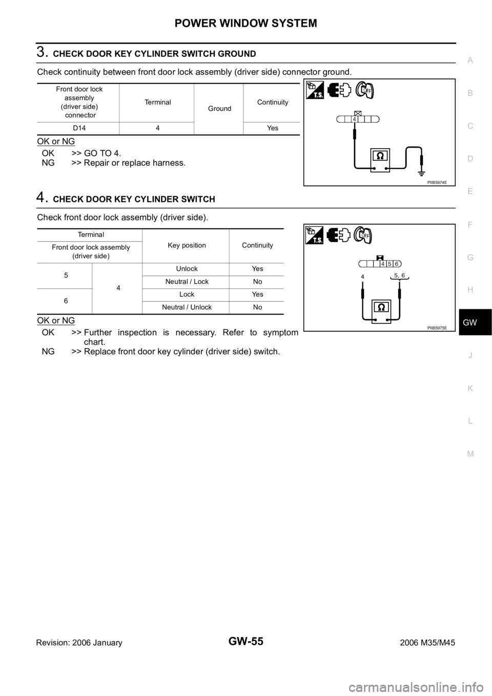
3. CHECK DOOR KEY CYLINDER SWITCH GROUND
Check continuity between front door lock assembly (driver side) connector ground.
OK or NG
OK >> GO TO 4.
NG >> Repair or replace harness.
4. CHECK DOOR KEY CYLINDER SWITCH
Check front door lock assembly (driver side).
OK or NG
OK >> Further inspection is necessary. Refer to symptom
chart.
NG >> Replace front door key cylinder (driver side) switch.
Front door lock
assembly
(driver side)
connectorTerminal
GroundContinuity
D14 4 Yes
PIIB5974E
Te r m i n a l
Key position Continuity
Front door lock assembly
(driver side)
5
4Unlock Yes
Neutral / Lock No
6Lock Yes
Neutral / Unlock No
PIIB5975E
Page 3575 of 5621

GW-56
POWER WINDOW SYSTEM
Revision: 2006 January2006 M35/M45
Power Window Serial Link Check (Passenger Side)NIS00223
1. CHECK POWER WINDOW SWITCH OUTPUT SIGNAL
With CONSULT-II
Check (“CDL LOCK SW ”, “CDL UNLOCK SW”) in DATA MONITOR mode for “POWER DOOR LOCK SYS-
TEM” with CONSULT-II. Refer to GW-31, "
DATE MONITOR" .
Without CONSULT-II
1. Remove key from ignition switch, and the door of driver side and passenger side is closed.
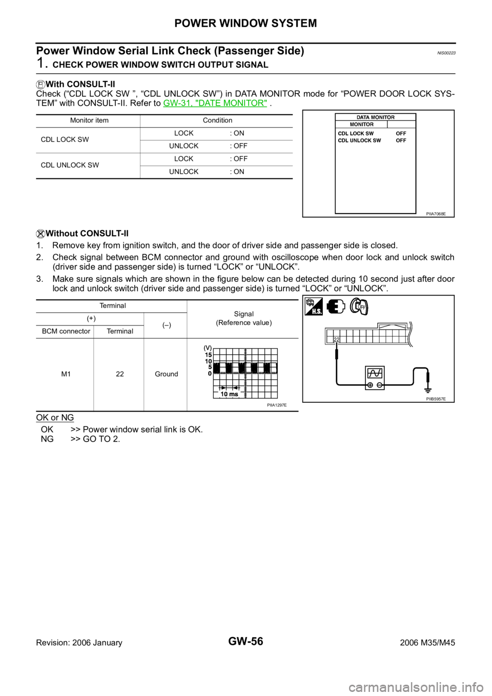
2. Check signal between BCM connector and ground with oscilloscope when door lock and unlock switch
(driver side and passenger side) is turned “LOCK” or “UNLOCK”.
3. Make sure signals which are shown in the figure below can be detected during 10 second just after door
lock and unlock switch (driver side and passenger side) is turned “LOCK” or “UNLOCK”.
OK or NG
OK >> Power window serial link is OK.
NG >> GO TO 2.
Monitor item Condition
CDL LOCK SW LOCK : ON
UNLOCK : OFF
CDL UNLOCK SW LOCK : OFF
UNLOCK : ON
PIIA7068E
Terminal
Signal
(Reference value) (+)
(–)
BCM connector Terminal
M1 22 Ground
PIIB5957EPIIA1297E
Page 3626 of 5621

REVERSE INTERLOCK DOOR MIRROR SYSTEM
GW-107
C
D
E
F
G
H
J
K
L
MA
B
GW
Revision: 2006 January2006 M35/M45
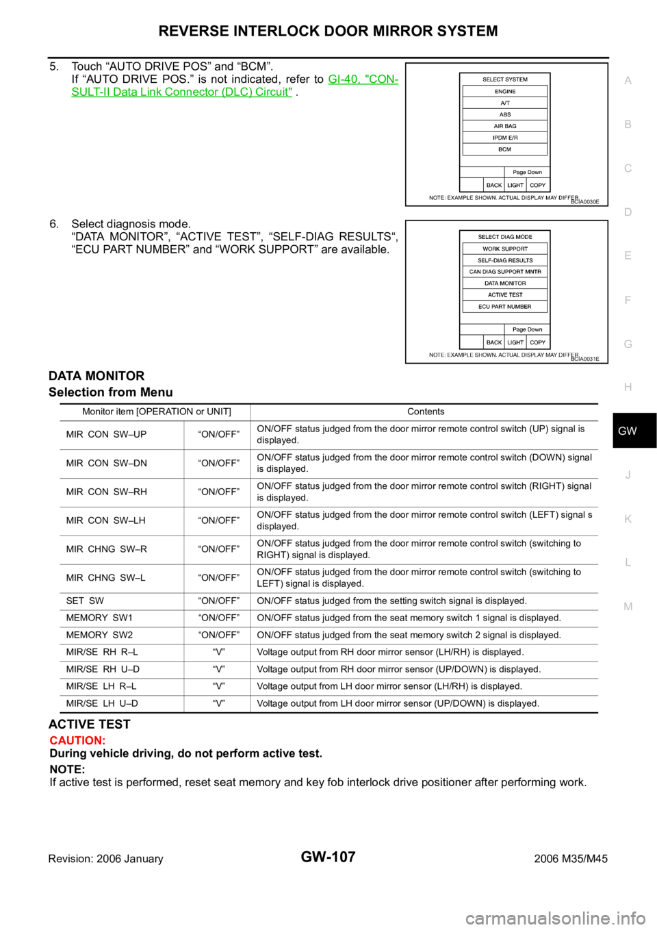
5. Touch “AUTO DRIVE POS” and “BCM”.
If “AUTO DRIVE POS.” is not indicated, refer to GI-40, "
CON-
SULT-II Data Link Connector (DLC) Circuit" .
6. Select diagnosis mode.
“DATA MONITOR”, “ACTIVE TEST”, “SELF-DIAG RESULTS“,
“ECU PART NUMBER” and “WORK SUPPORT” are available.
DATA MONITOR
Selection from Menu
ACTIVE TEST
CAUTION:
During vehicle driving, do not perform active test.
NOTE:
If active test is performed, reset seat memory and key fob interlock drive positioner after performing work.
BCIA0030E
BCIA0031E
Monitor item [OPERATION or UNIT] Contents
MIR CON SW–UP “ON/OFF”ON/OFF status judged from the door mirror remote control switch (UP) signal is
displayed.
MIR CON SW–DN “ON/OFF”ON/OFF status judged from the door mirror remote control switch (DOWN) signal
is displayed.
MIR CON SW–RH “ON/OFF”ON/OFF status judged from the door mirror remote control switch (RIGHT) signal
is displayed.
MIR CON SW–LH “ON/OFF”ON/OFF status judged from the door mirror remote control switch (LEFT) signal s
displayed.
MIR CHNG SW–R “ON/OFF”ON/OFF status judged from the door mirror remote control switch (switching to
RIGHT) signal is displayed.
MIR CHNG SW–L “ON/OFF”ON/OFF status judged from the door mirror remote control switch (switching to
LEFT) signal is displayed.
SET SW “ON/OFF” ON/OFF status judged from the setting switch signal is displayed.
MEMORY SW1 “ON/OFF” ON/OFF status judged from the seat memory switch 1 signal is displayed.
MEMORY SW2 “ON/OFF” ON/OFF status judged from the seat memory switch 2 signal is displayed.
MIR/SE RH R–L “V” Voltage output from RH door mirror sensor (LH/RH) is displayed.
MIR/SE RH U–D “V” Voltage output from RH door mirror sensor (UP/DOWN) is displayed.
MIR/SE LH R–L “V” Voltage output from LH door mirror sensor (LH/RH) is displayed.
MIR/SE LH U–D “V” Voltage output from LH door mirror sensor (UP/DOWN) is displayed.
Page 3670 of 5621

LAN-1
LAN SYSTEM
K ELECTRICAL
CONTENTS
C
D
E
F
G
H
I
J
L
M
SECTION LAN
A
B
LAN
Revision: 2006 January2006 M35/M45
LAN SYSTEM
CAN
PRECAUTIONS .......................................................... 7
Precautions for Supplemental Restraint System
(SRS) “AIR BAG” and “SEAT BELT PRE-TEN-
SIONER” .................................................................. 7
Precautions When Using CONSULT-II ..................... 7
CHECK POINTS FOR USING CONSULT-II ......... 7
Precautions For Trouble Diagnosis .......................... 7
CAN SYSTEM ....................................................... 7
Precautions For Harness Repair .............................. 8
CAN SYSTEM ....................................................... 8
TROUBLE DIAGNOSES WORK FLOW .................... 9
When Displaying CAN Communication System
Errors ....................................................................... 9
WHEN A MALFUNCTION IS DETECTED BY
CAN COMMUNICATION SYSTEM ....................... 9
WHEN A MALFUNCTION IS DETECTED
EXCEPT CAN COMMUNICATION SYSTEM ........ 9
TROUBLE DIAGNOSIS FLOW CHART ............. 10
Diagnosis Procedure ............................................... 11
SELECTING CAN SYSTEM TYPE (HOW TO
USE SPECIFICATION TABLE) ............................ 11
ACQUISITION OF DATA BY CONSULT-II .......... 12
HOW TO USE CHECK SHEET TABLE .............. 14
CAN Diagnostic Support Monitor ........................... 20
DESCRIPTION OF “CAN DIAG SUPPORT
MNTR” SCREEN FOR ECM ............................... 20
DESCRIPTION OF “CAN DIAG SUPPORT
MNTR” SCREEN FOR TCM ............................... 21
DESCRIPTION OF “CAN DIAG SUPPORT
MNTR” SCREEN FOR AWD CONTROL UNIT ... 21
DESCRIPTION OF “CAN DIAG SUPPORT
MNTR” SCREEN FOR AFS CONTROL UNIT .... 22
DESCRIPTION OF “CAN DIAG SUPPORT
MNTR” SCREEN FOR BCM ............................... 23
DESCRIPTION OF “CAN DIAG SUPPORT
MNTR” SCREEN FOR LDW CAMERA UNIT ..... 24
DESCRIPTION OF “CAN DIAG SUPPORT
MNTR” SCREEN FOR LOW TIRE PRESSURE WARNING CONTROL UNIT ............................... 25
DESCRIPTION OF “CAN DIAG SUPPORT
MNTR” SCREEN FOR INTELLIGENT KEY UNIT ... 26
DESCRIPTION OF “CAN DIAG SUPPORT
M N T R ” S C R E E N F O R U N I F I E D M E T E R A N D A /
C AMP. ................................................................. 27
DESCRIPTION OF “CAN DIAG SUPPORT
MNTR” SCREEN FOR AV(NAVI) CONTROL
UNIT .................................................................... 28
DESCRIPTION OF “CAN DIAG SUPPORT
MNTR” SCREEN FOR RAS CONTROL UNIT .... 29
DESCRIPTION OF “CAN DIAG SUPPORT
M N T R ” S C R E E N F O R P R E - C R A S H S E A T B E L T
CONTROL UNIT ................................................. 30
DESCRIPTION OF “CAN DIAG SUPPORT
MNTR” SCREEN FOR DRIVER SEAT CON-
TROL UNIT ...................................................... ... 31
DESCRIPTION OF “CAN DIAG SUPPORT
MNTR” SCREEN FOR ABS ACTUATOR AND
ELECTRIC UNIT (CONTROL UNIT) ................... 31
DESCRIPTION OF “CAN DIAG SUPPORT
MNTR” SCREEN FOR ICC SENSOR INTE-
GRATED UNIT .................................................... 32
DESCRIPTION OF “CAN DIAG SUPPORT
MNTR” SCREEN FOR IPDM E/R ....................... 33
CAN COMMUNICATION ........................................... 34
System Description ................................................. 34
CAN Communication Unit ....................................... 34
SYSTEM DIAGRAM ............................................ 34
INPUT/OUTPUT SIGNAL CHART ...................... 40
CAN SYSTEM (TYPE 1) ........................................... 48
Component Parts and Harness Connector Location ... 48
Schematic ............................................................... 49
Wiring Diagram — CAN — ..................................... 50
Check Sheet ........................................................... 53
CHECK SHEET RESULTS (EXAMPLE) ............. 56
Inspection Between TCM and Data Link Connector
Circuit ..................................................................
... 72
Inspection Between Data Link Connector and Driver
Seat Control Unit Circuit ......................................
... 73
Page 3671 of 5621

LAN-2Revision: 2006 January2006 M35/M45 Inspection Between Driver Seat Control Unit and
ABS Actuator and Electric Unit (Control Unit) Circuit ... 74
ECM Circuit Inspection ........................................... 75
TCM Circuit Inspection ........................................... 75
BCM Circuit Inspection ........................................... 76
Low Tire Pressure Warning Control Unit Circuit
Inspection ............................................................... 76
Steering Angle Sensor Circuit Inspection ............... 77
Intelligent Key Unit Circuit Inspection ..................... 77
Unified Meter and A/C Amp. Circuit Inspection ...... 78
AV Control Unit Circuit Inspection ........................... 78
Data Link Connector Circuit Inspection .................. 79
Driver Seat Control Unit Circuit Inspection ............. 79
ABS Actuator and Electric Unit (Control Unit) Circuit
Inspection ............................................................... 80
IPDM E/R Circuit Inspection ................................... 80
CAN Communication Circuit Inspection .................. 81
IPDM E/R Ignition Relay Circuit Inspection ............ 88
CAN SYSTEM (TYPE 2) ........................................... 89
Component Parts and Harness Connector Location ... 89
Schematic ............................................................... 90
Wiring Diagram — CAN — ..................................... 91
Check Sheet ........................................................... 94
CHECK SHEET RESULTS (EXAMPLE) ............. 97
Inspection Between TCM and Data Link Connector
Circuit ...................................................................113
Inspection Between Data Link Connector and Driver
Seat Control Unit Circuit ......................................
.114
Inspection Between Driver Seat Control Unit and
ABS Actuator and Electric Unit (Control Unit) Circuit .115
ECM Circuit Inspection .........................................116
TCM Circuit Inspection .........................................116
BCM Circuit Inspection .........................................117
Low Tire Pressure Warning Control Unit Circuit
Inspection .............................................................117
Steering Angle Sensor Circuit Inspection .............118
Intelligent Key Unit Circuit Inspection ...................118
Unified Meter and A/C Amp. Circuit Inspection ....119
NAVI Control Unit Circuit Inspection .....................119
Data Link Connector Circuit Inspection ................120
Driver Seat Control Unit Circuit Inspection ...........120
ABS Actuator and Electric Unit (Control Unit) Circuit
Inspection .............................................................121
IPDM E/R Circuit Inspection .................................121
CAN Communication Circuit Inspection ................122
IPDM E/R Ignition Relay Circuit Inspection ..........129
CAN SYSTEM (TYPE 3) .........................................130
Component Parts and Harness Connector Location .130
Schematic .............................................................131
Wiring Diagram — CAN — ...................................132
Check Sheet .........................................................136
CHECK SHEET RESULTS (EXAMPLE) ...........139
Inspection Between TCM and Data Link Connector
Circuit ...................................................................158
Inspection Between Data Link Connector and Pre-
Crash Seat Belt Control Unit Circuit .....................159
Inspection Between Pre-Crash Seat Belt Control
Unit and Driver Seat Control Unit Circuit ..............160
Inspection Between Driver Seat Control Unit and ABS Actuator and Electric Unit (Control Unit) Circuit .160
ECM Circuit Inspection .........................................161
TCM Circuit Inspection ......................................... .162
AFS Control Unit Circuit Inspection ......................162
BCM Circuit Inspection .........................................163
Low Tire Pressure Warning Control Unit Circuit
Inspection ..............................................................163
Steering Angle Sensor Circuit Inspection ..............164
Intelligent Key Unit Circuit Inspection ...................164
Unified Meter and A/C Amp. Circuit Inspection .....165
AV Control Unit Circuit Inspection .........................165
Data Link Connector Circuit Inspection .................166
Pre-Crash Seat Belt Control Unit Circuit Inspection .166
Driver Seat Control Unit Circuit Inspection ...........167
ABS Actuator and Electric Unit (Control Unit) Circuit
Inspection ..............................................................167
IPDM E/R Circuit Inspection .................................168
CAN Communication Circuit Inspection ................169
IPDM E/R Ignition Relay Circuit Inspection ...........176
CAN SYSTEM (TYPE 4) ..........................................177
Component Parts and Harness Connector Location .177
Schematic .............................................................178
Wiring Diagram — CAN — ...................................179
Check Sheet .........................................................183
CHECK SHEET RESULTS (EXAMPLE) ............186
Inspection Between TCM and Data Link Connector
Circuit ....................................................................205
Inspection Between Data Link Connector and Pre-
Crash Seat Belt Control Unit Circuit ......................206
Inspection Between Pre-Crash Seat Belt Control
Unit and Driver Seat Control Unit Circuit ..............207
Inspection Between Driver Seat Control Unit and
ABS Actuator and Electric Unit (Control Unit) Circuit .207
ECM Circuit Inspection .........................................208
TCM Circuit Inspection ......................................... .209
AFS Control Unit Circuit Inspection ......................209
BCM Circuit Inspection .........................................210
Low Tire Pressure Warning Control Unit Circuit
Inspection ..............................................................210
Steering Angle Sensor Circuit Inspection ..............211
Intelligent Key Unit Circuit Inspection ...................211
Unified Meter and A/C Amp. Circuit Inspection .....212
NAVI Control Unit Circuit Inspection .....................212
Data Link Connector Circuit Inspection .................213
Pre-Crash Seat Belt Control Unit Circuit Inspection .213
Driver Seat Control Unit Circuit Inspection ...........214
ABS Actuator and Electric Unit (Control Unit) Circuit
Inspection ..............................................................214
IPDM E/R Circuit Inspection ................................
.215
CAN Communication Circuit Inspection ................216
IPDM E/R Ignition Relay Circuit Inspection ...........223
CAN SYSTEM (TYPE 5) ..........................................224
Component Parts and Harness Connector Location .224
Schematic .............................................................225
Wiring Diagram — CAN — ...................................226
Check Sheet .........................................................230
CHECK SHEET RESULTS (EXAMPLE) ............233
Inspection Between TCM and Data Link Connector
Circuit ....................................................................255
Page 3672 of 5621

LAN-3
C
D
E
F
G
H
I
J
L
MA
B
LAN
Revision: 2006 January2006 M35/M45 Inspection Between Data Link Connector and Pre-
Crash Seat Belt Control Unit Circuit .....................256
Inspection Between Pre-Crash Seat Belt Control
Unit and Driver Seat Control Unit Circuit ..............257
Inspection Between Driver Seat Control Unit and
ABS Actuator and Electric Unit (Control Unit) Circuit .257
Inspection Between ABS Actuator and Electric Unit
and ICC Sensor Integrated Unit Circuit ................258
ECM Circuit Inspection .........................................259
TCM Circuit Inspection .........................................259
AFS Control Unit Circuit Inspection ......................260
BCM Circuit Inspection .........................................260
LDW Camera Unit Circuit Inspection ...................261
Low Tire Pressure Warning Control Unit Circuit
Inspection .............................................................261
Steering Angle Sensor Circuit Inspection .............262
Intelligent Key Unit Circuit Inspection ...................262
Unified Meter and A/C Amp. Circuit Inspection ....263
NAVI Control Unit Circuit Inspection .....................263
Data Link Connector Circuit Inspection ................264
Pre-Crash Seat Belt Control Unit Circuit Inspection .264
Driver Seat Control Unit Circuit Inspection ...........265
ABS Actuator and Electric Unit (Control Unit) Circuit
Inspection .............................................................265
ICC Sensor Integrated Unit Circuit Inspection .....266
IPDM E/R Circuit Inspection .................................266
CAN Communication Circuit Inspection ...............267
IPDM E/R Ignition Relay Circuit Inspection ..........274
CAN SYSTEM (TYPE 6) .........................................275
Component Parts and Harness Connector Location .275
Schematic ............................................................276
Wiring Diagram — CAN — ...................................277
Check Sheet .........................................................281
CHECK SHEET RESULTS (EXAMPLE) ...........284
Inspection Between TCM and Data Link Connector
Circuit ...................................................................303
Inspection Between Data Link Connector and RAS
Control Unit Circuit ...............................................304
Inspection Between RAS Control Unit and Driver
Seat Control Unit Circuit ......................................
.305
Inspection Between Driver Seat Control Unit and
ABS Actuator and Electric Unit (Control Unit) Circuit .305
ECM Circuit Inspection .........................................306
TCM Circuit Inspection .........................................306
AFS Control Unit Circuit Inspection ......................307
BCM Circuit Inspection .........................................307
Low Tire Pressure Warning Control Unit Circuit
Inspection .............................................................308
Steering Angle Sensor Circuit Inspection .............308
Intelligent Key Unit Circuit Inspection ...................309
Unified Meter and A/C Amp. Circuit Inspection ....309
AV Control Unit Circuit Inspection ........................310
Data Link Connector Circuit Inspection ................310
RAS Control Unit Circuit Inspection ...................... 311
Driver Seat Control Unit Circuit Inspection ............ 311
ABS Actuator and Electric Unit (Control Unit) Circuit
Inspection ............................................................
.312
IPDM E/R Circuit Inspection .................................312CAN Communication Circuit Inspection ...............313
IPDM E/R Ignition Relay Circuit Inspection ..........320
CAN SYSTEM (TYPE 7) .........................................321
Component Parts and Harness Connector Location .321
Schematic .............................................................322
Wiring Diagram — CAN — ...................................323
Check Sheet .........................................................327
CHECK SHEET RESULTS (EXAMPLE) ...........330
Inspection Between TCM and Data Link Connector
Circuit ...................................................................349
Inspection Between Data Link Connector and RAS
Control Unit Circuit ...............................................350
Inspection Between RAS Control Unit and Driver
Seat Control Unit Circuit ......................................
.351
Inspection Between Driver Seat Control Unit and
ABS Actuator and Electric Unit (Control Unit) Circuit .351
ECM Circuit Inspection .........................................352
TCM Circuit Inspection .........................................352
AFS Control Unit Circuit Inspection ......................353
BCM Circuit Inspection .........................................353
Low Tire Pressure Warning Control Unit Circuit
Inspection .............................................................354
Steering Angle Sensor Circuit Inspection .............354
Intelligent Key Unit Circuit Inspection ...................355
Unified Meter and A/C Amp. Circuit Inspection ....355
NAVI Control Unit Circuit Inspection .....................356
Data Link Connector Circuit Inspection ................356
RAS Control Unit Circuit Inspection ......................357
Driver Seat Control Unit Circuit Inspection ...........357
ABS Actuator and Electric Unit (Control Unit) Circuit
Inspection .............................................................358
IPDM E/R Circuit Inspection .................................358
CAN Communication Circuit Inspection ...............359
IPDM E/R Ignition Relay Circuit Inspection ..........366
CAN SYSTEM (TYPE 8) .........................................367
Component Parts and Harness Connector Location .367
Schematic .............................................................368
Wiring Diagram — CAN — ...................................369
Check Sheet .........................................................373
CHECK SHEET RESULTS (EXAMPLE) ...........376
Inspection Between TCM and Data Link Connector
Circuit ...................................................................397
Inspection Between Data Link Connector and RAS
Control Unit Circuit ...............................................398
Inspection Between RAS Control Unit and Pre-
Crash Seat Belt Control Unit Circuit .....................399
Inspection Between Pre-Crash Seat Belt Control
Unit and Driver Seat Control Unit Circuit ..............399
Inspection Between Driver Seat Control Unit and
ABS Actuator and Electric Unit (Control Unit) Circuit .400
ECM Circuit Inspection .........................................400
TCM Circuit Inspection .........................................401
AFS Control Unit Circuit Inspection ......................402
BCM Circuit Inspection .........................................402
Low Tire Pressure Warning Control Unit Circuit
Inspection ............................................................
.403
Steering Angle Sensor Circuit Inspection .............403
Intelligent Key Unit Circuit Inspection ...................404
Unified Meter and A/C Amp. Circuit Inspection ....404
Page 3673 of 5621

LAN-4Revision: 2006 January2006 M35/M45 AV Control Unit Circuit Inspection .........................405
Data Link Connector Circuit Inspection ................405
RAS Control Unit Circuit Inspection ......................406
Pre-Crash Seat Belt Control Unit Circuit Inspection .406
Driver Seat Control Unit Circuit Inspection ...........407
ABS Actuator and Electric Unit (Control Unit) Circuit
Inspection .............................................................407
IPDM E/R Circuit Inspection .................................408
CAN Communication Circuit Inspection ................409
IPDM E/R Ignition Relay Circuit Inspection ..........416
CAN SYSTEM (TYPE 9) .........................................417
Component Parts and Harness Connector Location .417
Schematic .............................................................418
Wiring Diagram — CAN — ...................................419
Check Sheet .........................................................423
CHECK SHEET RESULTS (EXAMPLE) ...........426
Inspection Between TCM and Data Link Connector
Circuit ...................................................................447
Inspection Between Data Link Connector and RAS
Control Unit Circuit ...............................................448
Inspection Between RAS Control Unit and Pre-
Crash Seat Belt Control Unit Circuit .....................449
Inspection Between Pre-Crash Seat Belt Control
Unit and Driver Seat Control Unit Circuit ..............449
Inspection Between Driver seat control unit and ABS
Actuator and Electric Unit (Control Unit) Circuit ....450
ECM Circuit Inspection .........................................450
TCM Circuit Inspection .........................................451
AFS Control Unit Circuit Inspection ......................452
BCM Circuit Inspection .........................................452
Low Tire Pressure Warning Control Unit Circuit
Inspection .............................................................453
Steering Angle Sensor Circuit Inspection .............453
Intelligent Key Unit Circuit Inspection ...................454
Unified Meter and A/C Amp. Circuit Inspection ....454
NAVI Control Unit Circuit Inspection .....................455
Data Link Connector Circuit Inspection ................455
RAS Control Unit Circuit Inspection ......................456
Pre-Crash Seat Belt Control Unit Circuit Inspection .456
Driver Seat Control Unit Circuit Inspection ...........457
ABS Actuator and Electric Unit (Control Unit) Circuit
Inspection .............................................................457
IPDM E/R Circuit Inspection .................................458
CAN Communication Circuit Inspection ................459
IPDM E/R Ignition Relay Circuit Inspection ..........466
CAN SYSTEM (TYPE 10) .......................................467
Component Parts and Harness Connector Location .467
Schematic .............................................................468
Wiring Diagram — CAN — ...................................469
Check Sheet .........................................................473
CHECK SHEET RESULTS (EXAMPLE) ...........476
Inspection Between TCM and Data Link Connector
Circuit ...................................................................500
Inspection Between Data Link Connector and RAS
Control Unit Circuit ...............................................501
Inspection Between RAS Control Unit and Pre-
Crash Seat Belt Control Unit Circuit .....................502
Inspection Between Pre-Crash Seat Belt Control
Unit and Driver Seat Control Unit Circuit ..............502Inspection Between Driver Seat Control Unit and
ABS Actuator and Electric Unit (Control Unit) Circuit .503
Inspection Between ABS Actuator and Electric Unit
and ICC Sensor Integrated Unit Circuit .................504
ECM Circuit Inspection .........................................504
TCM Circuit Inspection ......................................... .505
AFS Control Unit Circuit Inspection ......................505
BCM Circuit Inspection .........................................506
LDW Camera Unit Circuit Inspection ....................506
Low Tire Pressure Warning Control Unit Circuit
Inspection ..............................................................507
Steering Angle Sensor Circuit Inspection ..............507
Intelligent Key Unit Circuit Inspection ...................508
Unified Meter and A/C Amp. Circuit Inspection .....508
NAVI Control Unit Circuit Inspection .....................509
Data Link Connector Circuit Inspection .................509
RAS Control Unit Circuit Inspection ......................510
Pre-Crash Seat Belt Control Unit Circuit Inspection .510
Driver Seat Control Unit Circuit Inspection ...........511
ABS Actuator and Electric Unit (Control Unit) Circuit
Inspection ..............................................................511
ICC Sensor Integrated Unit Circuit Inspection ......512
IPDM E/R Circuit Inspection .................................512
CAN Communication Circuit Inspection ................513
IPDM E/R Ignition Relay Circuit Inspection ...........520
CAN SYSTEM (TYPE 11) ........................................521
Component Parts and Harness Connector Location .521
Schematic .............................................................522
Wiring Diagram — CAN — ...................................523
Check Sheet .........................................................526
CHECK SHEET RESULTS (EXAMPLE) ............529
Inspection Between TCM and Data Link Connector
Circuit ....................................................................546
Inspection Between Data Link Connector and Driver
Seat Control Unit Circuit .......................................547
Inspection Between Driver Seat Control Unit and
ABS Actuator and Electric Unit (Control Unit) Circuit .548
ECM Circuit Inspection .........................................549
TCM Circuit Inspection ......................................... .549
AWD Control Unit Circuit Inspection .....................550
BCM Circuit Inspection .........................................550
Low Tire Pressure Warning Control Unit Circuit
Inspection ..............................................................551
Steering Angle Sensor Circuit Inspection ..............551
Intelligent Key Unit Circuit Inspection ...................552
Unified Meter and A/C Amp. Circuit Inspection .....552
AV Control Unit Circuit Inspection .........................553
Data Link Connector Circuit Inspection ................
.553
Driver Seat Control Unit Circuit Inspection ...........554
ABS Actuator and Electric Unit (Control Unit) Circuit
Inspection ..............................................................554
IPDM E/R Circuit Inspection .................................555
CAN Communication Circuit Inspection ................556
IPDM E/R Ignition Relay Circuit Inspection ...........563
CAN SYSTEM (TYPE 12) ........................................564
Component Parts and Harness Connector Location .564
Schematic .............................................................565
Wiring Diagram — CAN — ...................................566
Check Sheet .........................................................569
Page 3674 of 5621

LAN-5
C
D
E
F
G
H
I
J
L
MA
B
LAN
Revision: 2006 January2006 M35/M45 CHECK SHEET RESULTS (EXAMPLE) ...........572
Inspection Between TCM and Data Link Connector
Circuit ...................................................................589
Inspection Between Data Link Connector and Driver
Seat Control Unit Circuit ......................................
.590
Inspection Between Driver Seat Control Unit and
ABS Actuator and Electric Unit (Control Unit) Circuit .591
ECM Circuit Inspection .........................................592
TCM Circuit Inspection .........................................592
AWD Control Unit Circuit Inspection ....................593
BCM Circuit Inspection .........................................593
Low Tire Pressure Warning Control Unit Circuit
Inspection .............................................................594
Steering Angle Sensor Circuit Inspection .............594
Intelligent Key Unit Circuit Inspection ...................595
Unified Meter and A/C Amp. Circuit Inspection ....595
NAVI Control Unit Circuit Inspection .....................596
Data Link Connector Circuit Inspection ................596
Driver Seat Control Unit Circuit Inspection ...........597
ABS Actuator and Electric Unit (Control Unit) Circuit
Inspection .............................................................597
IPDM E/R Circuit Inspection .................................598
CAN Communication Circuit Inspection ...............599
IPDM E/R Ignition Relay Circuit Inspection ..........606
CAN SYSTEM (TYPE 13) .......................................607
Component Parts and Harness Connector Location .607
Schematic ............................................................608
Wiring Diagram — CAN — ...................................609
Check Sheet .........................................................613
CHECK SHEET RESULTS (EXAMPLE) ...........616
Inspection Between TCM and Data Link Connector
Circuit ...................................................................636
Inspection Between Data Link Connector and Pre-
Crash Seat Belt Control Unit Circuit .....................637
Inspection Between Pre-Crash Seat Belt Control
Unit and Driver Seat Control Unit Circuit ..............638
Inspection Between Driver Seat Control Unit and
ABS Actuator and Electric Unit (Control Unit) Circuit .638
ECM Circuit Inspection .........................................639
TCM Circuit Inspection .........................................640
AWD Control Unit Circuit Inspection ....................640
AFS Control Unit Circuit Inspection ......................641
BCM Circuit Inspection .........................................641
Low Tire Pressure Warning Control Unit Circuit
Inspection .............................................................642
Steering Angle Sensor Circuit Inspection .............642
Intelligent Key Unit Circuit Inspection ...................643
Unified Meter and A/C Amp. Circuit Inspection ....643
AV Control Unit Circuit Inspection ........................644
Data Link Connector Circuit Inspection ................644
Pre-Crash Seat Belt Control Unit Circuit Inspection .645
Driver Seat Control Unit Circuit Inspection ...........645
ABS Actuator and Electric Unit (Control Unit) Circuit
Inspection .............................................................646
IPDM E/R Circuit Inspection .................................646
CAN Communication Circuit Inspection ...............647
IPDM E/R Ignition Relay Circuit Inspection ..........655
CAN SYSTEM (TYPE 14) .......................................656
Component Parts and Harness Connector Location .656Schematic .............................................................657
Wiring Diagram — CAN — ...................................658
Check Sheet .........................................................662
CHECK SHEET RESULTS (EXAMPLE) ...........665
Inspection Between TCM and Data Link Connector
Circuit ...................................................................685
Inspection Between Data Link Connector and Pre-
Crash Seat Belt Control Unit Circuit .....................686
Inspection Between Pre-Crash Seat Belt Control
Unit and Driver Seat Control Unit Circuit ..............687
Inspection Between Driver Seat Control Unit and
ABS Actuator and Electric Unit (Control Unit) Circuit .687
ECM Circuit Inspection .........................................688
TCM Circuit Inspection .........................................689
AWD Control Unit Circuit Inspection .....................689
AFS Control Unit Circuit Inspection ......................690
BCM Circuit Inspection .........................................690
Low Tire Pressure Warning Control Unit Circuit
Inspection .............................................................691
Steering Angle Sensor Circuit Inspection .............691
Intelligent Key Unit Circuit Inspection ...................692
Unified Meter and A/C Amp. Circuit Inspection ....692
NAVI Control Unit Circuit Inspection .....................693
Data Link Connector Circuit Inspection ................693
Pre-Crash Seat Belt Control Unit Circuit Inspection .694
Driver Seat Control Unit Circuit Inspection ...........694
ABS Actuator and Electric Unit (Control Unit) Circuit
Inspection .............................................................695
IPDM E/R Circuit Inspection .................................695
CAN Communication Circuit Inspection ...............696
IPDM E/R Ignition Relay Circuit Inspection ..........704
CAN SYSTEM (TYPE 15) .......................................705
Component Parts and Harness Connector Location .705
Schematic .............................................................706
Wiring Diagram — CAN — ...................................707
Check Sheet .........................................................711
CHECK SHEET RESULTS (EXAMPLE) ...........714
Inspection Between TCM and Data Link Connector
Circuit ...................................................................737
Inspection Between Data Link Connector and Pre-
Crash Seat Belt Control Unit Circuit .....................738
Inspection Between Pre-Crash Seat Belt Control
Unit and Driver Seat Control Unit Circuit ..............739
Inspection Between Driver Seat Control Unit and
ABS Actuator and Electric Unit (Control Unit) Circuit .739
Inspection Between ABS Actuator and Electric Unit
and ICC Sensor Integrated Unit Circuit ................740
ECM Circuit Inspection .........................................741
TCM Circuit Inspection .........................................741
AWD Control Unit Circuit Inspection .....................742
AFS Control Unit Circuit Inspection ......................742
BCM Circuit Inspection .........................................743
LDW Camera Unit Circuit Inspection ....................743
Low Tire Pressure Warning Control Unit Circuit
Inspection .............................................................744
Steering Angle Sensor Circuit Inspection .............744
Intelligent Key Unit Circuit Inspection ...................745
Unified Meter and A/C Amp. Circuit Inspection ....745
NAVI Control Unit Circuit Inspection .....................746