2006 INFINITI M35 check oil
[x] Cancel search: check oilPage 4810 of 5621
CHASSIS AND BODY MAINTENANCE
MA-33
C
D
E
F
G
H
I
J
K
MA
B
MA
Revision: 2006 January2006 M35/M45
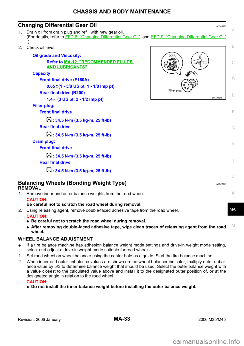
Changing Differential Gear OilNLS00086
1. Drain oil from drain plug and refill with new gear oil.
(For details, refer to FFD-8, "
Changing Differential Gear Oil" and RFD-9, "Changing Differential Gear Oil"
.)
2. Check oil level.
Balancing Wheels (Bonding Weight Type)NLS00087
REMOVAL
1. Remove inner and outer balance weights from the road wheel.
CAUTION:
Be careful not to scratch the road wheel during removal.
2. Using releasing agent, remove double-faced adhesive tape from the road wheel.
CAUTION:
Be careful not to scratch the road wheel during removal.
After removing double-faced adhesive tape, wipe clean traces of releasing agent from the road
wheel.
WHEEL BALANCE ADJUSTMENT
If a tire balance machine has adhesion balance weight mode settings and drive-in weight mode setting,
select and adjust a drive-in weight mode suitable for road wheels.
1. Set road wheel on wheel balancer using the center hole as a guide. Start the tire balance machine.
2. When inner and outer unbalance values are shown on the wheel balancer indicator, multiply outer unbal-
ance value by 5/3 to determine balance weight that should be used. Select the outer balance weight with
a value closest to the calculated value above and install it to the designated outer position of, or at the
designated angle in relation to the road wheel.
CAUTION:
Do not install the inner balance weight before installing the outer balance weight. Oil grade and Viscosity:
Refer to MA-12, "
RECOMMENDED FLUIDS
AND LUBRICANTS" .
Capacity:
Front final drive (F160A)
0.65 (1 - 3/8 US pt, 1 - 1/8 lmp pt)
Rear final drive (R200)
1.4 (3 US pt, 2 - 1/2 lmp pt)
Filler plug:
Front final drive
: 34.5 N-m (3.5 kg-m, 25 ft-lb)
Rear final drive
: 34.5 N-m (3.5 kg-m, 25 ft-lb)
Drain plug:
Front final drive
: 34.5 N-m (3.5 kg-m, 25 ft-lb)
Rear final drive
: 34.5 N-m (3.5 kg-m, 25 ft-lb)
SDIA1151E
Page 4814 of 5621
CHASSIS AND BODY MAINTENANCE
MA-37
C
D
E
F
G
H
I
J
K
MA
B
MA
Revision: 2006 January2006 M35/M45
Checking Power Steering Fluid and LinesNLS0008E
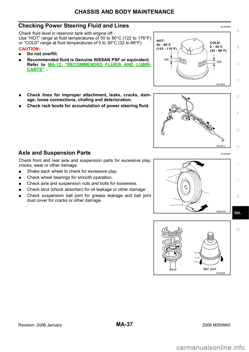
Check fluid level in reservoir tank with engine off.
Use “HOT” range at fluid temperatures of 50 to 80
C (122 to 176F)
or “COLD” range at fluid temperatures of 0 to 30
C (32 to 86F).
CAUTION:
Do not overfill.
Recommended fluid is Genuine NISSAN PSF or equivalent.
Refer to MA-12, "
RECOMMENDED FLUIDS AND LUBRI-
CANTS" .
Check lines for improper attachment, leaks, cracks, dam-
age, loose connections, chafing and deterioration.
Check rack boots for accumulation of power steering fluid.
Axle and Suspension PartsNLS0008F
Check front and rear axle and suspension parts for excessive play,
cracks, wear or other damage.
Shake each wheel to check for excessive play.
Check wheel bearings for smooth operation.
Check axle and suspension nuts and bolts for looseness.
Check strut (shock absorber) for oil leakage or other damage.
Check suspension ball joint for grease leakage and ball joint
dust cover for cracks or other damage.
SST850C
SST851C
SMA525A
SFA392B
Page 4816 of 5621
CHASSIS AND BODY MAINTENANCE
MA-39
C
D
E
F
G
H
I
J
K
MA
B
MA
Revision: 2006 January2006 M35/M45
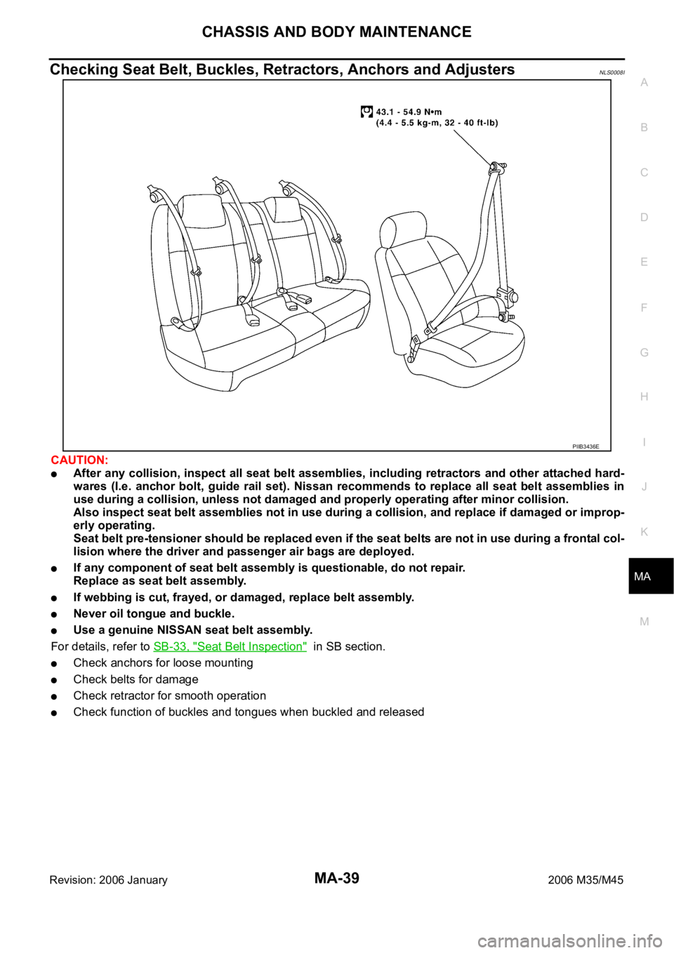
Checking Seat Belt, Buckles, Retractors, Anchors and AdjustersNLS0008I
CAUTION:
After any collision, inspect all seat belt assemblies, including retractors and other attached hard-
wares (I.e. anchor bolt, guide rail set). Nissan recommends to replace all seat belt assemblies in
use during a collision, unless not damaged and properly operating after minor collision.
Also inspect seat belt assemblies not in use during a collision, and replace if damaged or improp-
erly operating.
Seat belt pre-tensioner should be replaced even if the seat belts are not in use during a frontal col-
lision where the driver and passenger air bags are deployed.
If any component of seat belt assembly is questionable, do not repair.
Replace as seat belt assembly.
If webbing is cut, frayed, or damaged, replace belt assembly.
Never oil tongue and buckle.
Use a genuine NISSAN seat belt assembly.
For details, refer to SB-33, "
Seat Belt Inspection" in SB section.
Check anchors for loose mounting
Check belts for damage
Check retractor for smooth operation
Check function of buckles and tongues when buckled and released
PIIB3436E
Page 4817 of 5621
MA-40
SERVICE DATA AND SPECIFICATIONS (SDS)
Revision: 2006 January2006 M35/M45
SERVICE DATA AND SPECIFICATIONS (SDS)PFP:00030
Standard and LimitNLS0008J
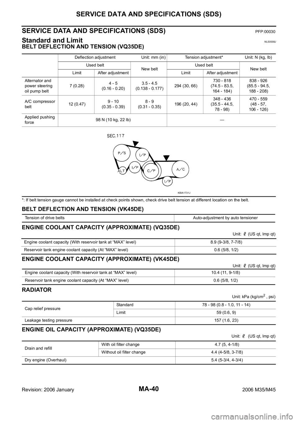
BELT DEFLECTION AND TENSION (VQ35DE)
*: If belt tension gauge cannot be installed at check points shown, check drive belt tension at different location on the belt.
BELT DEFLECTION AND TENSION (VK45DE)
ENGINE COOLANT CAPACITY (APPROXIMATE) (VQ35DE)
Unit: (US qt, lmp qt)
ENGINE COOLANT CAPACITY (APPROXIMATE) (VK45DE)
Unit: (US qt, lmp qt)
RADIATOR
Unit: kPa (kg/cm2 , psi)
ENGINE OIL CAPACITY (APPROXIMATE) (VQ35DE)
Unit: (US qt, lmp qt) Deflection adjustment Unit: mm (in) Tension adjustment* Unit: N (kg, lb)
Used belt
New beltUsed belt
New belt
Limit After adjustment Limit After adjustment
Alternator and
power steering
oil pump belt7 (0.28)4 - 5
(0.16 - 0.20)3.5 - 4.5
(0.138 - 0.177)294 (30, 66)730 - 818
(74.5 - 83.5,
164 - 184)838 - 926
(85.5 - 94.5,
188 - 208)
A/C compressor
belt12 (0.47)9 - 10
(0.35 - 0.39)8 - 9
(0.31 - 0.35)196 (20, 44)348 - 436
(35.5 - 44.5,
78 - 98)470 - 559
(48 - 57,
106 - 126)
Applied pushing
force98 N (10 kg, 22 lb) —
KBIA1731J
Tension of drive belts Auto-adjustment by auto tensioner
Engine coolant capacity (With reservoir tank at “MAX” level) 8.9 (9-3/8, 7-7/8)
Reservoir tank engine coolant capacity (At “MAX” level) 0.6 (5/8, 1/2)
Engine coolant capacity (With reservoir tank at “MAX” level) 10.4 (11, 9-1/8)
Reservoir tank engine coolant capacity (At “MAX” level) 0.6 (5/8, 1/2)
Cap relief pressureStandard 78 - 98 (0.8 - 1.0, 11 - 14)
Limit 59 (0.6, 9)
Leakage testing pressure157 (1.6, 23)
Drain and refill With oil filter change 4.7 (5, 4-1/8)
Without oil filter change 4.4 (4-5/8, 3-7/8)
Dry engine (Overhaul) 5.4 (5-3/4, 4-3/4)
Page 4851 of 5621
PG-24
IPDM E/R (INTELLIGENT POWER DISTRIBUTION MODULE ENGINE ROOM)
Revision: 2006 January2006 M35/M45
Auto Active TestNKS004E7
DESCRIPTION
In auto active test mode, operation inspection can be performed when IPDM E/R sends a drive signal to the
following systems:
Rear window defogger
Front wiper (LO, HI)
Tail lamps, parking lamps and license plate lamps
Front fog lamps
Headlamps (LO, HI)
A/C compressor (magnetic clutch)
Cooling fan
Oil pressure warning lamp
OPERATION PROCEDURE
1. Close hood and front door (passenger side), and then lift wiper arms away from windshield (to prevent
glass damage by wiper operation).
NOTE:
When auto active test is performed with hood opened, sprinkle water on windshield beforehand.
2. Turn ignition switch OFF.
3. Turn ignition switch ON, and within 20 seconds, press driver's door switch 10 times (close other doors).
Then turn ignition switch OFF.
4. Turn ignition switch ON within 10 seconds after ignition switch OFF.
5. When auto active test mode is actuated, horn chirps once. Oil pressure warning lamp starts blinking.
6. After a series of operations is repeated three times, auto active test is completed.
NOTE:
When auto active test mode has to be cancelled halfway, turn ignition switch OFF.
CAUTION:
Never start the engine.
If the engine starting operation is made, delete DTC on the self-diag results of CONSULT-II.
Refer to BL-81, "
CONSULT-II Application Items" .
Be sure to inspect GW-52, "Door Switch Check" when the auto active test cannot be performed.
Page 4954 of 5621

PS-1
POWER STEERING SYSTEM
G STEERING
CONTENTS
C
D
E
F
H
I
J
K
L
M
SECTION PS
A
B
PS
Revision: 2006 January2006 M35/M45
POWER STEERING SYSTEM
PRECAUTIONS .......................................................... 3
Precautions for Supplemental Restraint System
(SRS) “AIR BAG” and “SEAT BELT PRE-TEN-
SIONER” .................................................................. 3
Precautions Necessary for Steering Wheel Rotation
after Battery Disconnect ........................................... 3
OPERATION PROCEDURE ................................. 3
Precautions for Steering System .............................. 4
PREPARATION ........................................................... 5
Special Service Tools [SST] ..................................... 5
Commercial Service Tools ........................................ 6
NOISE, VIBRATION AND HARSHNESS (NVH)
TROUBLESHOOTING ................................................ 7
NVH Trouble Shooting Chart .................................... 7
POWER STEERING FLUID ........................................ 8
Checking Fluid Level ...........................................
..... 8
Checking Fluid Leakage ........................................... 8
Air Bleeding Hydraulic System ................................. 8
STEERING WHEEL .................................................. 10
On-Vehicle Inspection and Service ........................ 10
CHECKING CONDITION OF INSTALLATION .... 10
CHECKING STEERING WHEEL PLAY .............. 10
CHECKING NEUTRAL POSITION STEERING
WHEEL ............................................................... 10
CHECKING STEERING WHEEL TURNING
FORCE ................................................................ 10
CHECKING FRONT WHEEL TURNING ANGLE .... 11
Removal and Installation ........................................ 12
REMOVAL ........................................................
... 12
INSTALLATION ................................................... 12
STEERING COLUMN ............................................... 13
Removal and Installation ........................................ 13
COMPONENTS .................................................. 13
REMOVAL OF UPPER JOINT, COLLAR, HOLE
COVER SEAL, HOLE COVER, LOWER SHAFT
AND LOWER JOINT ........................................... 14
INSPECTION AFTER REMOVAL ....................... 14INSTALLATION OF UPPER JOINT, COLLAR,
HOLE COVER SEAL, HOLE COVER, LOWER
SHAFT AND LOWER JOINT .............................. 14
REMOVAL OF STEERING COLUMN ASSEM-
BLY ...................................................................... 15
INSPECTION AFTER REMOVAL ....................... 16
INSTALLATION OF STEERING COLUMN
ASSEMBLY ......................................................... 16
INSPECTION AFTER INSTALLATION ................ 16
Disassembly and Assembly .................................... 17
COMPONENTS ................................................... 17
DISASSEMBLY ................................................... 17
INSPECTION AFTER DISASSEMBLY ................ 17
ASSEMBLY ......................................................... 17
INSPECTION AFTER ASSEMBLY ...................... 17
POWER STEERING GEAR ...................................... 18
Removal and Installation ........................................ 18
COMPONENTS ................................................... 18
REMOVAL ........................................................
... 18
INSTALLATION ................................................... 19
INSPECTION AFTER INSTALLATION ................ 19
Disassembly and Assembly .................................
... 20
COMPONENTS ................................................... 20
DISASSEMBLY ................................................... 21
INSPECTION AFTER DISASSEMBLY ................ 22
ASSEMBLY ......................................................... 24
POWER STEERING OIL PUMP ............................... 29
On-Vehicle Inspection and Service ......................... 29
CHECKING RELIEF OIL PRESSURE ................ 29
Removal and Installation ........................................ 29
REMOVAL ........................................................
... 29
INSTALLATION ................................................... 29
Disassembly and Assembly (Models with VK45DE) ... 30
COMPONENTS ................................................... 30
INSPECTION BEFORE DISASSEMBLY ............. 30
DISASSEMBLY ................................................... 31
INSPECTION AFTER DISASSEMBLY ................ 31
Page 4961 of 5621
PS-8
POWER STEERING FLUID
Revision: 2006 January2006 M35/M45
POWER STEERING FLUIDPFP:KLF20
Checking Fluid LevelNGS000D5
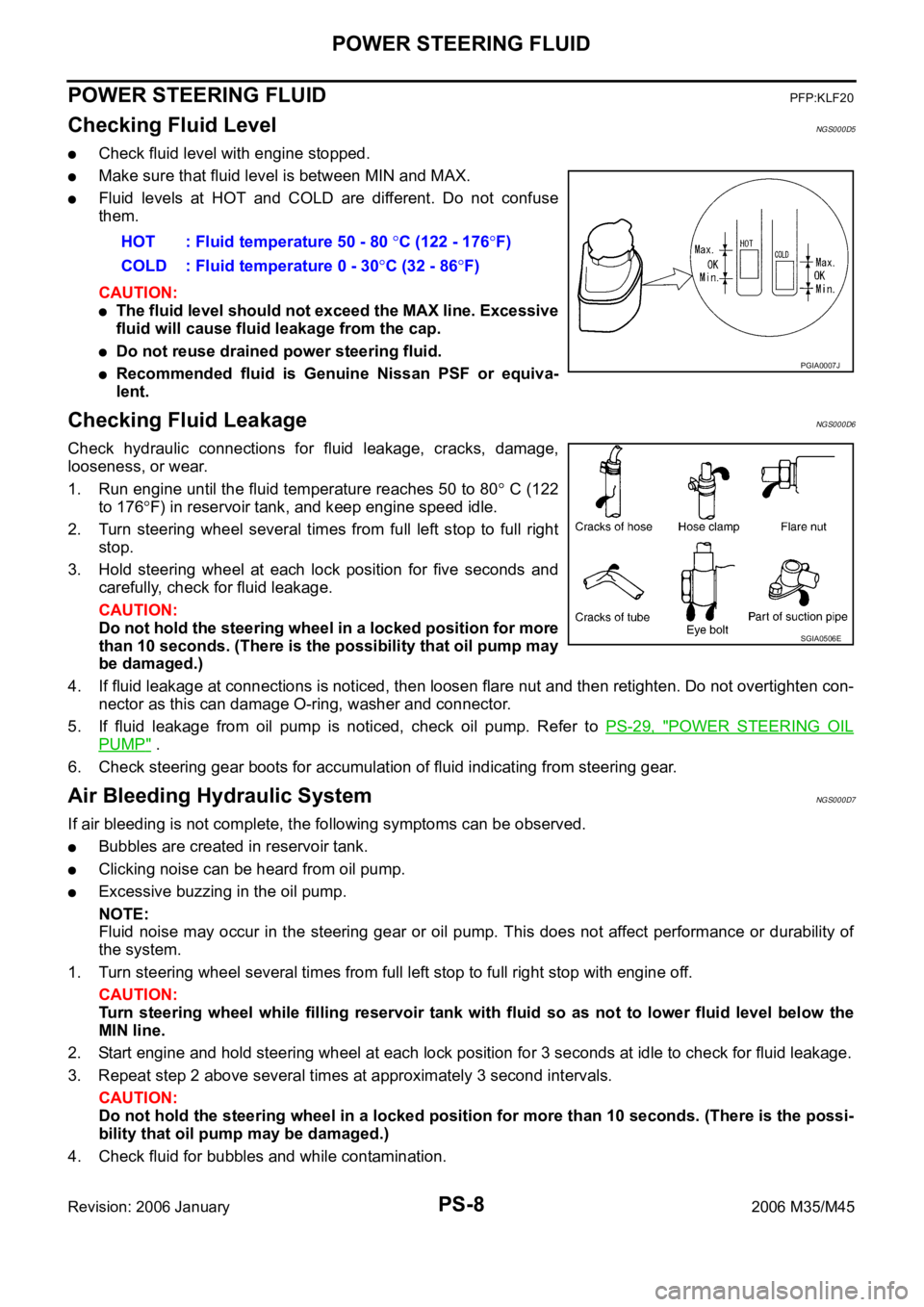
Check fluid level with engine stopped.
Make sure that fluid level is between MIN and MAX.
Fluid levels at HOT and COLD are different. Do not confuse
them.
CAUTION:
The fluid level should not exceed the MAX line. Excessive
fluid will cause fluid leakage from the cap.
Do not reuse drained power steering fluid.
Recommended fluid is Genuine Nissan PSF or equiva-
lent.
Checking Fluid LeakageNGS000D6
Check hydraulic connections for fluid leakage, cracks, damage,
looseness, or wear.
1. Run engine until the fluid temperature reaches 50 to 80
C (122
to 176
F) in reservoir tank, and keep engine speed idle.
2. Turn steering wheel several times from full left stop to full right
stop.
3. Hold steering wheel at each lock position for five seconds and
carefully, check for fluid leakage.
CAUTION:
Do not hold the steering wheel in a locked position for more
than 10 seconds. (There is the possibility that oil pump may
be damaged.)
4. If fluid leakage at connections is noticed, then loosen flare nut and then retighten. Do not overtighten con-
nector as this can damage O-ring, washer and connector.
5. If fluid leakage from oil pump is noticed, check oil pump. Refer to PS-29, "
POWER STEERING OIL
PUMP" .
6. Check steering gear boots for accumulation of fluid indicating from steering gear.
Air Bleeding Hydraulic SystemNGS000D7
If air bleeding is not complete, the following symptoms can be observed.
Bubbles are created in reservoir tank.
Clicking noise can be heard from oil pump.
Excessive buzzing in the oil pump.
NOTE:
Fluid noise may occur in the steering gear or oil pump. This does not affect performance or durability of
the system.
1. Turn steering wheel several times from full left stop to full right stop with engine off.
CAUTION:
Turn steering wheel while filling reservoir tank with fluid so as not to lower fluid level below the
MIN line.
2. Start engine and hold steering wheel at each lock position for 3 seconds at idle to check for fluid leakage.
3. Repeat step 2 above several times at approximately 3 second intervals.
CAUTION:
Do not hold the steering wheel in a locked position for more than 10 seconds. (There is the possi-
bility that oil pump may be damaged.)
4. Check fluid for bubbles and while contamination.HOT : Fluid temperature 50 - 80
C (122 - 176F)
COLD : Fluid temperature 0 - 30
C (32 - 86F)
PGIA0007J
SGIA0506E
Page 4963 of 5621
PS-10
STEERING WHEEL
Revision: 2006 January2006 M35/M45
STEERING WHEELPFP:48430
On-Vehicle Inspection and ServiceNGS000D8
CHECKING CONDITION OF INSTALLATION
Check installation conditions of steering gear assembly, front suspension assembly, axle and steering col-
umn assembly.
Check if movement exists when steering wheel is moved up and down, to the left and right and to the axial
direction.
Check steering gear assembly mounting bolts and nut for looseness. Refer to PS-18, "COMPONENTS" .
CHECKING STEERING WHEEL PLAY
Turn steering wheel so that front wheels come to the straight-ahead position. Start engine and lightly turn
steering wheel to the left and right until front wheels start to move. Measure steering wheel movement on
the outer circumference.
When the measurement value is outside the standard value, check backlash for each joint of steering col-
umn assembly and installation condition of steering gear assembly.
CHECKING NEUTRAL POSITION STEERING WHEEL
Make sure that steering gear assembly, steering column assembly and steering wheel are installed in the
correct position.
Perform neutral position inspection after wheel alignment. Refer to FSU-6, "Wheel Alignment Inspection"
(2WD), FSU-23, "Wheel Alignment Inspection" (AWD).
Set vehicle to the straight-ahead position and confirm steering wheel is in the neutral position.
Loosen outer socket lock nut and turn inner socket to left and right equally to make fine adjustments if
steering wheel is not in the neutral position.
CHECKING STEERING WHEEL TURNING FORCE
1. Park vehicle on a level and dry surface, set parking brake.
2. Start engine.
3. Bring power steering fluid up to adequate operating temperature. [Make sure temperature of fluid is
approximately 50 to 80
C (122 to 176F).]
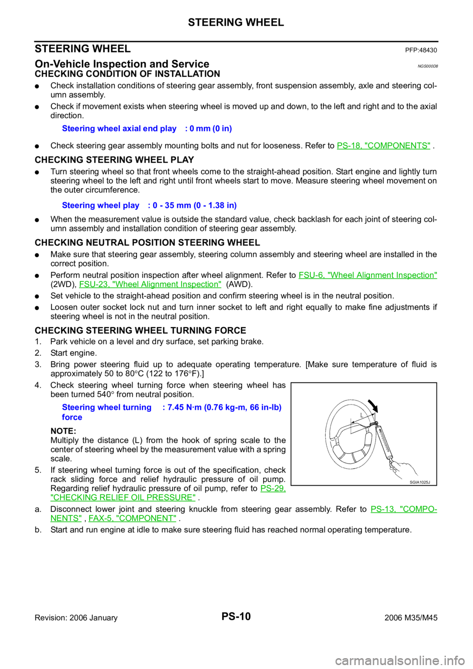
4. Check steering wheel turning force when steering wheel has
been turned 540
from neutral position.
NOTE:
Multiply the distance (L) from the hook of spring scale to the
center of steering wheel by the measurement value with a spring
scale.
5. If steering wheel turning force is out of the specification, check
rack sliding force and relief hydraulic pressure of oil pump.
Regarding relief hydraulic pressure of oil pump, refer to PS-29,
"CHECKING RELIEF OIL PRESSURE" .
a. Disconnect lower joint and steering knuckle from steering gear assembly. Refer to PS-13, "
COMPO-
NENTS" , FAX-5, "COMPONENT" .
b. Start and run engine at idle to make sure steering fluid has reached normal operating temperature. Steering wheel axial end play : 0 mm (0 in)
Steering wheel play : 0 - 35 mm (0 - 1.38 in)
Steering wheel turning
force: 7.45 Nꞏm (0.76 kg-m, 66 in-lb)
SGIA1025J