2006 INFINITI M35 check oil
[x] Cancel search: check oilPage 5097 of 5621

RSU-16
REAR LOWER LINK & COIL SPRING
Revision: 2006 January2006 M35/M45
REAR LOWER LINK & COIL SPRINGPFP:551B0
Removal and InstallationNES000JF
REMOVAL
1. Remove tire with a power tool.
2. Set a jack under rear lower link to relieve the coil spring tension.
3. Loosen mounting bolt and nut of rear lower link inside of suspension member, and then remove mounting
bolt and nut inside of axle with a power tool.
4. Slowly lower jack, then remove upper seat, coil spring and rubber sheet from rear lower link.
5. Remove mounting bolt and nut inside of suspension member to remove rear lower link with a power tool.
INSPECTION AFTER REMOVAL
Check rear lower link, bushing and coil spring for deformation, cracks, and damage. Replace rear lower link
and coil spring if there are.
INSTALLATION
Installation is the reverse order of removal. For tightening torque. Refer to RSU-7, "Components" .
CAUTION:
Do not reuse non-reusable parts.
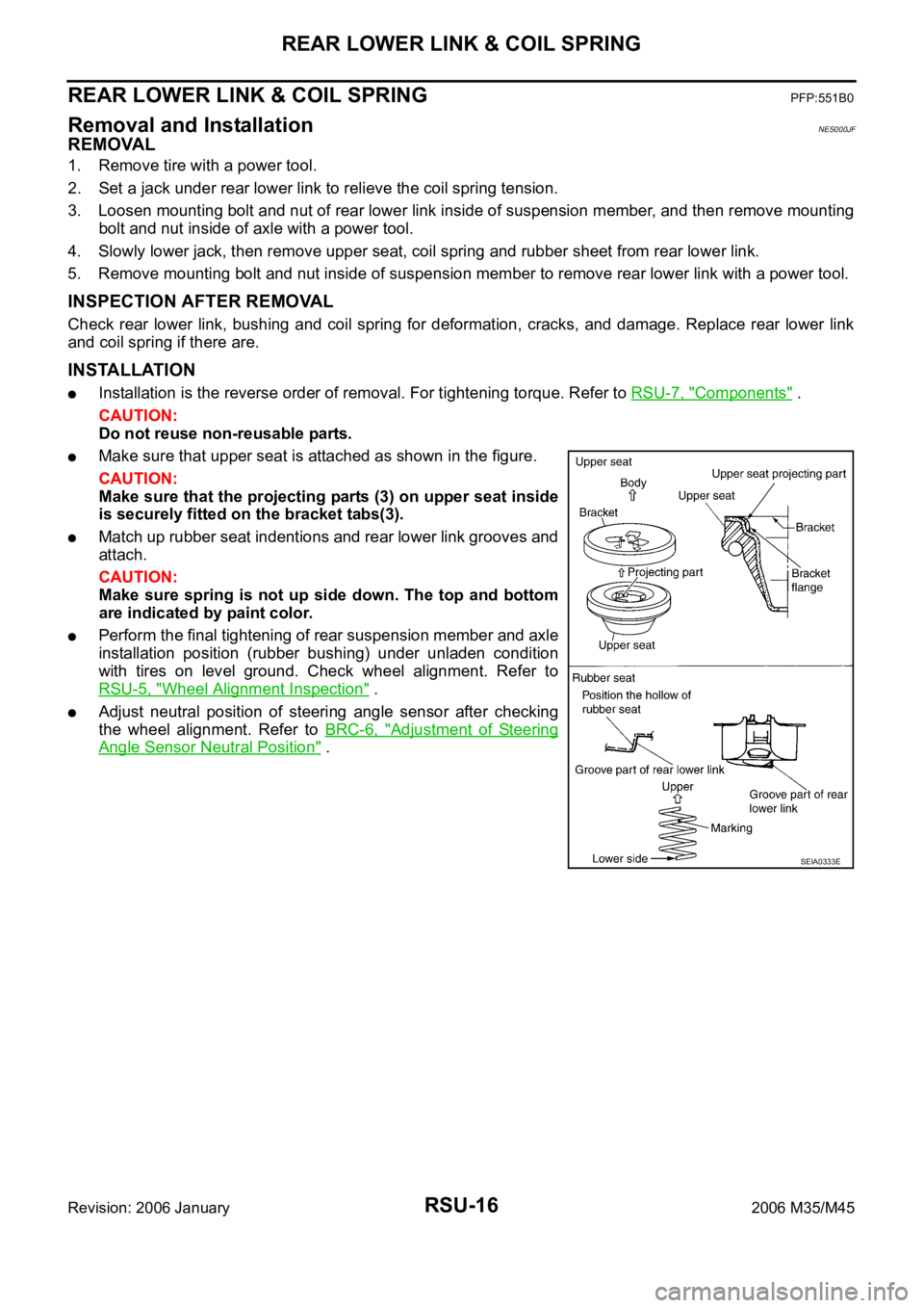
Make sure that upper seat is attached as shown in the figure.
CAUTION:
Make sure that the projecting parts (3) on upper seat inside
is securely fitted on the bracket tabs(3).
Match up rubber seat indentions and rear lower link grooves and
attach.
CAUTION:
Make sure spring is not up side down. The top and bottom
are indicated by paint color.
Perform the final tightening of rear suspension member and axle
installation position (rubber bushing) under unladen condition
with tires on level ground. Check wheel alignment. Refer to
RSU-5, "
Wheel Alignment Inspection" .
Adjust neutral position of steering angle sensor after checking
the wheel alignment. Refer to BRC-6, "
Adjustment of Steering
Angle Sensor Neutral Position" .
SEIA0333E
Page 5101 of 5621

SB-2
PRECAUTIONS
Revision: 2006 January2006 M35/M45
PRECAUTIONSPFP:00001
Precautions for Supplemental Restraint System (SRS) “AIR BAG” and “SEAT
BELT PRE-TENSIONER”
NHS0007V
The Supplemental Restraint System such as “AIR BAG” and “SEAT BELT PRE-TENSIONER”, used along
with a front seat belt, helps to reduce the risk or severity of injury to the driver and front passenger for certain
types of collision. This system includes seat belt switch inputs and dual stage front air bag modules. The SRS
system uses the seat belt switches to determine the front air bag deployment, and may only deploy one front
air bag, depending on the severity of a collision and whether the front occupants are belted or unbelted.
Information necessary to service the system safely is included in the SRS and SB section of this Service Man-
ual.
WAR NING :
To avoid rendering the SRS inoperative, which could increase the risk of personal injury or death
in the event of a collision which would result in air bag inflation, all maintenance must be per-
formed by an authorized NISSAN/INFINITI dealer.
Improper maintenance, including incorrect removal and installation of the SRS, can lead to per-
sonal injury caused by unintentional activation of the system. For removal of Spiral Cable and Air
Bag Module, see the SRS section.
Do not use electrical test equipment on any circuit related to the SRS unless instructed to in this
Service Manual. SRS wiring harnesses can be identified by yellow and/or orange harnesses or
harness connectors.
Precaution for Seat Belt ServiceNHS0007W
CAUTION:
Before removing the front seat belt pre-tensioner assembly, turn the ignition switch off, discon-
nect the both battery cables and wait at least 3 minutes.
Do not use electrical test equipment for front seat belt pre-tensioner connector.
After replacing or reinstalling front seat belt pre-tensioner assembly, or reconnecting front seat
belt pre-tensioner connector, check the system function. Refer to SRS-19, "
SRS Operation Check"
.
Do not use disassemble buckle or seat belt assembly.
Replace anchor bolts if they are deformed or worn out.
Never oil tongue and buckle.
If any component of seat belt assembly is questionable, do not repair. Replace the whole seat belt
assembly.
If webbing is cut, frayed, or damaged, replace seat belt assembly.
When replacing seat belt assembly, use a genuine NISSAN seat belt assembly.
AFTER A COLLISION
WAR NING :
Inspect all seat belt assemblies including retractors and attaching hardware after any collision.
NISSAN recommends that all seat belt assemblies in use during a collision be replaced unless the col-
lision was minor and the belts show no damage and continue to operate properly. Failure to do so
could result in serious personal injury in an accident. Seat belt assemblies not in use during a colli-
sion should also be replaced if either damage or improper operation is noted. Seat belt pre-tensioner
should be replaced even if the seat belts are not in use during a frontal collision in which the air bags
are deployed.
Replace any seat belt assembly (including anchor bolts) if:
The seat belt was in use at the time of a collision (except for minor collisions and the belts, retractors and
buckles show no damage and continue to operate properly).
The seat belt was damaged in an accident. (i.e. torn webbing, bent retractor or guide).
The seat belt attaching point was damaged in an accident. Inspect the seat belt attaching area for damage
or distortion and repair as necessary before installing a new seat belt assembly.
Anchor bolts are deformed or worn out.
The front seat belt pre-tensioner should be replaced even if the seat belts are not in use during the colli-
sion in which the air bags are deployed.
Page 5175 of 5621

SC-38
CHARGING SYSTEM
Revision: 2006 January2006 M35/M45
Removal (AWD Models)
1. Disconnect the battery cable from the negative terminal.
2. Remove power steering oil reservoir tank from the bracket.
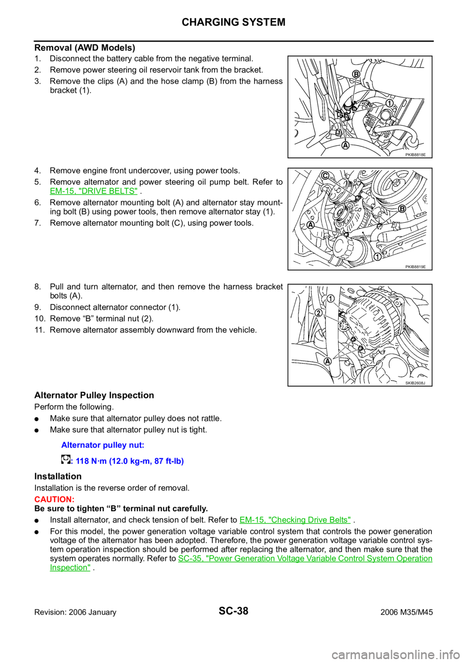
3. Remove the clips (A) and the hose clamp (B) from the harness
bracket (1).
4. Remove engine front undercover, using power tools.
5. Remove alternator and power steering oil pump belt. Refer to
EM-15, "
DRIVE BELTS" .
6. Remove alternator mounting bolt (A) and alternator stay mount-
ing bolt (B) using power tools, then remove alternator stay (1).
7. Remove alternator mounting bolt (C), using power tools.
8. Pull and turn alternator, and then remove the harness bracket
bolts (A).
9. Disconnect alternator connector (1).
10. Remove “B” terminal nut (2).
11. Remove alternator assembly downward from the vehicle.
Alternator Pulley Inspection
Perform the following.
Make sure that alternator pulley does not rattle.
Make sure that alternator pulley nut is tight.
Installation
Installation is the reverse order of removal.
CAUTION:
Be sure to tighten “B” terminal nut carefully.
Install alternator, and check tension of belt. Refer to EM-15, "Checking Drive Belts" .
For this model, the power generation voltage variable control system that controls the power generation
voltage of the alternator has been adopted. Therefore, the power generation voltage variable control sys-
tem operation inspection should be performed after replacing the alternator, and then make sure that the
system operates normally. Refer to SC-35, "
Power Generation Voltage Variable Control System Operation
Inspection" .
PKIB8818E
PKIB8819E
SKIB2608J
Alternator pulley nut:
: 118 Nꞏm (12.0 kg-m, 87 ft-lb)
Page 5184 of 5621

PRECAUTIONS
SE-3
C
D
E
F
G
H
J
K
L
MA
B
SE
Revision: 2006 January2006 M35/M45
PRECAUTIONSPFP:00001
Precautions for Supplemental Restraint System (SRS) “AIR BAG” and “SEAT
BELT PRE-TENSIONER”
NIS0025I
The Supplemental Restraint System such as “AIR BAG” and “SEAT BELT PRE-TENSIONER”, used along
with a front seat belt, helps to reduce the risk or severity of injury to the driver and front passenger for certain
types of collision. This system includes seat belt switch inputs and dual stage front air bag modules. The SRS
system uses the seat belt switches to determine the front air bag deployment, and may only deploy one front
air bag, depending on the severity of a collision and whether the front occupants are belted or unbelted.
Information necessary to service the system safely is included in the SRS and SB section of this Service Man-
ual.
WAR NING :
To avoid rendering the SRS inoperative, which could increase the risk of personal injury or death
in the event of a collision which would result in air bag inflation, all maintenance must be per-
formed by an authorized NISSAN/INFINITI dealer.
Improper maintenance, including incorrect removal and installation of the SRS, can lead to per-
sonal injury caused by unintentional activation of the system. For removal of Spiral Cable and Air
Bag Module, see the SRS section.
Do not use electrical test equipment on any circuit related to the SRS unless instructed to in this
Service Manual. SRS wiring harnesses can be identified by yellow and/or orange harnesses or
harness connectors.
Service NoticeNIS0025J
When removing or installing various parts, place a cloth or padding onto the vehicle body to prevent
scratches.
Handle trim, molding, instruments, grille, etc. carefully during removing or installing. Be careful not to oil or
damage them.
Apply sealing compound where necessary when installing parts.
When applying sealing compound, be careful that the sealing compound does not protrude from parts.
When replacing any metal parts (for example body outer panel, members, etc.), be sure to take rust pre-
vention measures.
Precautions for WorkNIS0025K
When removing or disassembling each component, be careful not to damage or deform it. If a component
may be subject to interference, be sure to protect it with a shop cloth.
When removing (disengaging) components with a screwdriver or similar tool, be sure to wrap the compo-
nent with a shop cloth or vinyl tape to protect it.
Protect the removed parts with a shop cloth and keep them.
Replace a deformed or damaged clip.
If a part is specified as a non-reusable part, always replace it with new one.
Be sure to tighten bolts and nuts securely to the specified torque.
After re-installation is completed, be sure to check that each part works normally.
Follow the steps below to clean components.
–Water soluble foul: Dip a soft cloth into lukewarm water, and wring the water out of the cloth to wipe the
fouled area.
Then rub with a soft and dry cloth.
–Oily foul: Dip a soft cloth into lukewarm water with mild detergent (concentration: within 2 to 3%), and wipe
the fouled area.
Then dip a cloth into fresh water, and wring the water out of the cloth to wipe the detergent off. Then rub
with a soft and dry cloth.
Do not use organic solvent such as thinner, benzene, alcohol, and gasoline.
For genuine leather seats, use a genuine leather seat cleaner.
Page 5424 of 5621
![INFINITI M35 2006 Factory Service Manual TROUBLE DIAGNOSIS
STC-9
[EPS]
C
D
E
F
H
I
J
K
L
MA
B
STC
Revision: 2006 January2006 M35/M45
For Fast and Accurate Trouble DiagnosisNGS000E1
Check the following items with the vehicle stopped
Is air pr INFINITI M35 2006 Factory Service Manual TROUBLE DIAGNOSIS
STC-9
[EPS]
C
D
E
F
H
I
J
K
L
MA
B
STC
Revision: 2006 January2006 M35/M45
For Fast and Accurate Trouble DiagnosisNGS000E1
Check the following items with the vehicle stopped
Is air pr](/manual-img/42/57023/w960_57023-5423.png)
TROUBLE DIAGNOSIS
STC-9
[EPS]
C
D
E
F
H
I
J
K
L
MA
B
STC
Revision: 2006 January2006 M35/M45
For Fast and Accurate Trouble DiagnosisNGS000E1
Check the following items with the vehicle stopped
Is air pressure and size of tires proper?
Is the specified part used for the steering wheel?
Is control unit a genuine part?
Are there any fluid leakage from steering gear assembly, power steering oil pump, and hydraulic pipes,
etc? Refer to PS-8, "
POWER STEERING FLUID" .
Is the fluid level proper? Refer to PS-8, "POWER STEERING FLUID" .
Is the wheel alignment adjusted properly? Refer to FSU-19, "SERVICE DATA AND SPECIFICATIONS
(SDS)" (2WD), FSU-36, "SERVICE DATA AND SPECIFICATIONS (SDS)" (AWD).
Are there any damage or modification to suspension or body resulting in increased weight or altered
ground clearance?
Check each link installation condition of suspension and axle.
Check each connector connection condition.
Check the following items while driving the vehicle
Check conditions when the malfunction occurred (5W 1H).
Is the engine condition normal?
Basic InspectionNGS000E2
POWER SUPPLY CIRCUIT TERMINAL LOOSENESS AND BATTERY
Check battery terminals for looseness on both positive and negative ones and ground connection. Also make
sure that battery voltage does not drop.
Inspection: Power Steering Control Unit Power Supply Circuit and GroundNGS000E3
1. CHECK POWER STEERING CONTROL UNIT CONNECTOR
Turn ignition switch OFF, disconnect power steering control unit harness connector, and check terminal for
deformation, disconnection, looseness, etc.
OK or NG
OK >> GO TO 2.
NG >> Connector terminal connection is loose, damaged, open, or shorted. Repair or replace the termi-
nal.
2. CHECK POWER STEERING CONTROL UNIT GROUND CIRCUIT
Disconnect power steering control unit harness connector M8, and
then check continuity between power steering control unit harness
connector M8 and ground.
OK or NG
OK >> GO TO 3.
NG >> Ground circuit open or shorted. Repair or replace any
inoperative parts. Terminal 2 – Ground : Continuity exist.
SGIA1231E
Page 5428 of 5621
![INFINITI M35 2006 Factory Service Manual REAR ACTIVE STEER
STC-13
[RAS]
C
D
E
F
H
I
J
K
L
MA
B
STC
Revision: 2006 January2006 M35/M45
[RAS]REAR ACTIVE STEERPFP:55705
Removal and InstallationNGS000E5
COMPONENTS
REMOVAL
1. Remove coil spring. INFINITI M35 2006 Factory Service Manual REAR ACTIVE STEER
STC-13
[RAS]
C
D
E
F
H
I
J
K
L
MA
B
STC
Revision: 2006 January2006 M35/M45
[RAS]REAR ACTIVE STEERPFP:55705
Removal and InstallationNGS000E5
COMPONENTS
REMOVAL
1. Remove coil spring.](/manual-img/42/57023/w960_57023-5427.png)
REAR ACTIVE STEER
STC-13
[RAS]
C
D
E
F
H
I
J
K
L
MA
B
STC
Revision: 2006 January2006 M35/M45
[RAS]REAR ACTIVE STEERPFP:55705
Removal and InstallationNGS000E5
COMPONENTS
REMOVAL
1. Remove coil spring. Refer to RSU-16, "REAR LOWER LINK & COIL SPRING" .
2. Disconnect harness connector from RAS actuator assembly and rear suspension member.
3. Remove fixing bolts and nuts of RAS actuator assembly (1), and
then remove RAS actuator assembly (1) from rear suspension
member.
INSTALLATION
Installation is the reverse order of removal. For tightening torque, refer to STC-13, "COMPONENTS" .
When installing RAS actuator assembly to rear suspension member, check the mounting surfaces of RAS
actuator assembly and rear suspension member for oil, dirt, sand, or other foreign materials.
To perform the neutral position adjustment. Refer to STC-14, "Neutral Position Adjustment" .
1. Rear lower link 2. Decenter cam 3. RAS actuator assembly
Refer to GI-11, "
Components" , for the symbols in the figure.
SGIA1238E
SGIA1239E
Page 5447 of 5621
![INFINITI M35 2006 Factory Service Manual STC-32
[RAS]
TROUBLE DIAGNOSIS
Revision: 2006 January2006 M35/M45
For Fast and Accurate Trouble DiagnosisNGS000EN
Check the following items with the vehicle stopped
Is air pressure and size of tires p INFINITI M35 2006 Factory Service Manual STC-32
[RAS]
TROUBLE DIAGNOSIS
Revision: 2006 January2006 M35/M45
For Fast and Accurate Trouble DiagnosisNGS000EN
Check the following items with the vehicle stopped
Is air pressure and size of tires p](/manual-img/42/57023/w960_57023-5446.png)
STC-32
[RAS]
TROUBLE DIAGNOSIS
Revision: 2006 January2006 M35/M45
For Fast and Accurate Trouble DiagnosisNGS000EN
Check the following items with the vehicle stopped
Is air pressure and size of tires proper?
Is the specified part used for the steering wheel?
Is control unit a genuine part?
Are there any fluid leakage from steering gear assembly, power steering oil pump, and hydraulic pipes,
etc? Refer to PS-8, "
POWER STEERING FLUID" .
Is the fluid level proper? Refer to PS-8, "POWER STEERING FLUID" .
Is the wheel alignment is adjusted properly? Refer to FSU-19, "SERVICE DATA AND SPECIFICATIONS
(SDS)" (2WD), FSU-36, "SERVICE DATA AND SPECIFICATIONS (SDS)" (AWD).
Are there any damage or modification to suspension or body resulting in increased weight or altered
ground clearance?
Check each link installation condition of suspension and axle.
Is the battery voltage proper?
Check each connector connection condition.
Check the following items while driving the vehicle
Conditions when the error occurred (5W 1H).
Is the engine is normal?
Basic InspectionNGS000EO
BASIC INSPECTION 1: POWER SUPPLY CIRCUIT TERMINAL LOOSENESS AND BATTERY
Check battery terminals for looseness on both positive and negative ones and ground connection. Also make
sure that battery voltage does not drop.
BASIC INSPECTION 2: RAS WARNING LAMP INSPECTION
1. Make sure RAS warning lamp turns on when ignition switch is turned ON.
If it does not turn on, refer to STC-33, "Trouble Diagnosis Chart" .
2. Make sure that RAS warning lamp turns off when the engine is started after ignition switch is turned ON. If
it does not turn off, perform self-diagnosis. Refer to STC-28, "
SELF-DIAG RESULT MODE" .
3. Always erase DTC memory after completing self-diagnosis. Refer to STC-29, "
How to Erase Self-Diag-
nostic Results" .
BASIC INSPECTION 3: RAS CONTROL UNIT POWER SUPPLY CIRCUIT AND GROUND CIR-
CUIT INSPECTION
1. CHECK RAS CONTROL UNIT CONNECTOR
Turn ignition switch OFF, disconnect RAS control unit harness connector, and check terminal for deformation,
disconnection, looseness, etc.
OK or NG
OK >> GO TO 2.
NG >> Poor connection of connector terminal. Repair or replace the terminal.
2. CHECK RAS CONTROL UNIT GROUND CIRCUIT
1. Disconnect RAS control unit harness connector B127, and then
check continuity between RAS control unit harness connector
B127 and ground.
OK or NG
OK >> GO TO 3.
NG >> Ground circuit open or shorted. Repair or replace any
inoperative parts. Terminal 34 – Ground : Continuity
SGIA1244E
Page 5474 of 5621

TRANSFER FLUID
TF-9
C
E
F
G
H
I
J
K
L
MA
B
TF
Revision: 2006 January2006 M35/M45
TRANSFER FLUIDPFP:31001
ReplacementNDS000D9
DRAINING
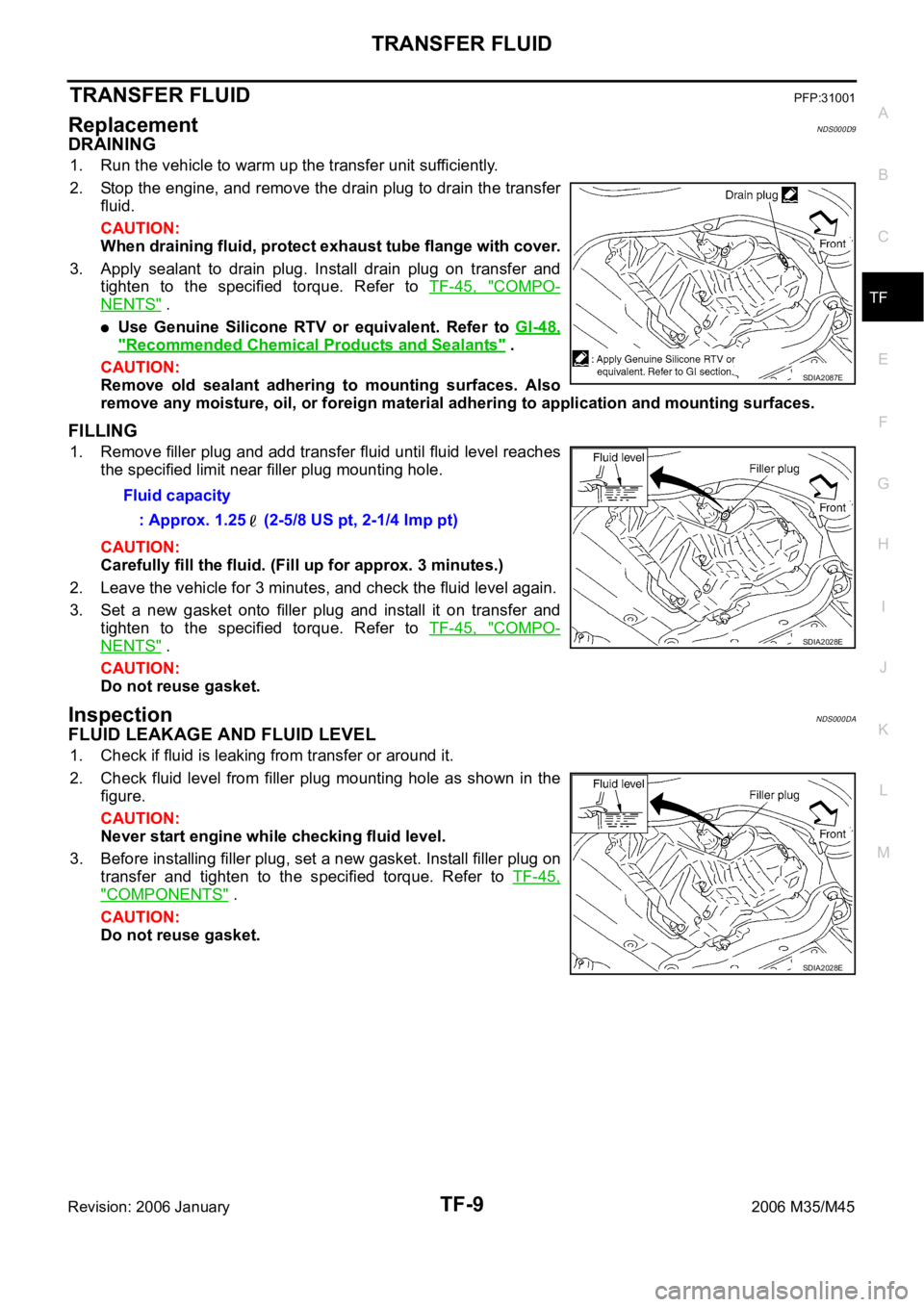
1. Run the vehicle to warm up the transfer unit sufficiently.
2. Stop the engine, and remove the drain plug to drain the transfer
fluid.
CAUTION:
When draining fluid, protect exhaust tube flange with cover.
3. Apply sealant to drain plug. Install drain plug on transfer and
tighten to the specified torque. Refer to TF-45, "
COMPO-
NENTS" .
Use Genuine Silicone RTV or equivalent. Refer to GI-48,
"Recommended Chemical Products and Sealants" .
CAUTION:
Remove old sealant adhering to mounting surfaces. Also
remove any moisture, oil, or foreign material adhering to application and mounting surfaces.
FILLING
1. Remove filler plug and add transfer fluid until fluid level reaches
the specified limit near filler plug mounting hole.
CAUTION:
Carefully fill the fluid. (Fill up for approx. 3 minutes.)
2. Leave the vehicle for 3 minutes, and check the fluid level again.
3. Set a new gasket onto filler plug and install it on transfer and
tighten to the specified torque. Refer to TF-45, "
COMPO-
NENTS" .
CAUTION:
Do not reuse gasket.
InspectionNDS000DA
FLUID LEAKAGE AND FLUID LEVEL
1. Check if fluid is leaking from transfer or around it.
2. Check fluid level from filler plug mounting hole as shown in the
figure.
CAUTION:
Never start engine while checking fluid level.
3. Before installing filler plug, set a new gasket. Install filler plug on
transfer and tighten to the specified torque. Refer to TF-45,
"COMPONENTS" .
CAUTION:
Do not reuse gasket.
SDIA2087E
Fluid capacity
: Approx. 1.25 (2-5/8 US pt, 2-1/4 lmp pt)
SDIA2028E
SDIA2028E