Page 4654 of 5621
TURN SIGNAL AND HAZARD WARNING LAMPS
LT-227
C
D
E
F
G
H
I
J
L
MA
B
LT
Revision: 2006 January2006 M35/M45
Hazard Warning Lamp Does Not Operate But Turn Signal Lamp OperateNKS003RV
1. CHECK CIRCUIT BETWEEN HAZARD SWITCH AND BCM
With CONSULT-II
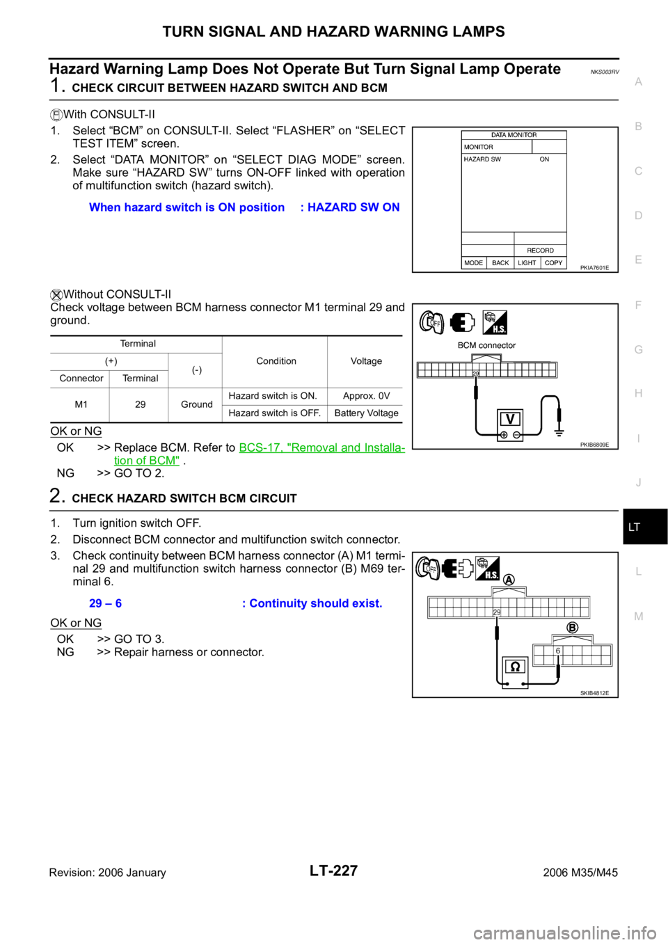
1. Select “BCM” on CONSULT-II. Select “FLASHER” on “SELECT
TEST ITEM” screen.
2. Select “DATA MONITOR” on “SELECT DIAG MODE” screen.
Make sure “HAZARD SW” turns ON-OFF linked with operation
of multifunction switch (hazard switch).
Without CONSULT-II
Check voltage between BCM harness connector M1 terminal 29 and
ground.
OK or NG
OK >> Replace BCM. Refer to BCS-17, "Removal and Installa-
tion of BCM" .
NG >> GO TO 2.
2. CHECK HAZARD SWITCH BCM CIRCUIT
1. Turn ignition switch OFF.
2. Disconnect BCM connector and multifunction switch connector.
3. Check continuity between BCM harness connector (A) M1 termi-
nal 29 and multifunction switch harness connector (B) M69 ter-
minal 6.
OK or NG
OK >> GO TO 3.
NG >> Repair harness or connector.When hazard switch is ON position : HAZARD SW ON
PKIA7601E
Terminal
Condition Voltage (+)
(-)
Connector Terminal
M1 29 GroundHazard switch is ON. Approx. 0V
Hazard switch is OFF. Battery Voltage
PKIB6809E
29 – 6 : Continuity should exist.
SKIB4812E
Page 4655 of 5621
LT-228
TURN SIGNAL AND HAZARD WARNING LAMPS
Revision: 2006 January2006 M35/M45
3. CHECK HAZARD SWITCH GROUND CIRCUIT
Check continuity between multifunction switch harness connector
terminal 14 and ground.
OK or NG
OK >> GO TO 4.
NG >> Repair harness or connector.
4. CHECK HAZARD SWITCH
Check continuity multifunction switch (hazard switch).
OK or NG
OK >> Replace BCM. Replace BCM if turn signal lamp does
not work after setting the connector again. Refer to
BCS-17, "
Removal and Installation of BCM" .
NG >> Replace multifunction switch. Refer to AV- 2 9 2 , "
Multifunction Switch" .
Turn Signal Indicator Lamp Does Not OperateNKS003RW
1. CHECK BULB
Check bulb of turn signal indicator lamp in combination meter.
OK or NG
OK >> Replace combination meter.
NG >> Replace indicator bulb.14 – Ground : Continuity should exist.
SKIB4813E
Multifunction switch
(Hazard switch)
Condition Continuity
Terminal
614Hazard switch is ON. Yes
Hazard switch is OFF. No
SKIB4814E
Page 4660 of 5621
COMBINATION SWITCH
LT-233
C
D
E
F
G
H
I
J
L
MA
B
LT
Revision: 2006 January2006 M35/M45
Combination Switch Reading FunctionNKS003S6
For details, refer to BCS-3, "COMBINATION SWITCH READING FUNCTION" .
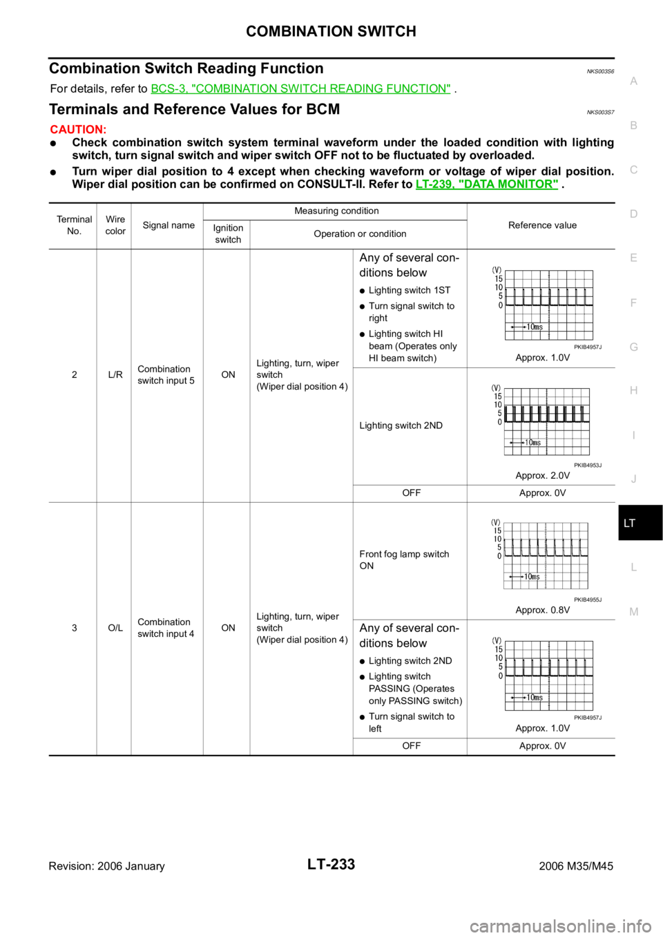
Terminals and Reference Values for BCMNKS003S7
CAUTION:
Check combination switch system terminal waveform under the loaded condition with lighting
switch, turn signal switch and wiper switch OFF not to be fluctuated by overloaded.
Turn wiper dial position to 4 except when checking waveform or voltage of wiper dial position.
Wiper dial position can be confirmed on CONSULT-II. Refer to LT-239, "
DATA MONITOR" .
Terminal
No.Wire
colorSignal nameMeasuring condition
Reference value
Ignition
switchOperation or condition
2L/RCombination
switch input 5ONLighting, turn, wiper
switch
(Wiper dial position 4)
Any of several con-
ditions below
Lighting switch 1ST
Turn signal switch to
right
Lighting switch HI
beam (Operates only
HI beam switch)Approx. 1.0V
Lighting switch 2ND
Approx. 2.0V
OFF Approx. 0V
3O/LCombination
switch input 4ONLighting, turn, wiper
switch
(Wiper dial position 4)Front fog lamp switch
ON
Approx. 0.8V
Any of several con-
ditions below
Lighting switch 2ND
Lighting switch
PASSING (Operates
only PASSING switch)
Turn signal switch to
leftApprox. 1.0V
OFF Approx. 0V
PKIB4957J
PKIB4953J
PKIB4955J
PKIB4957J
Page 4665 of 5621
LT-238
COMBINATION SWITCH
Revision: 2006 January2006 M35/M45
CONSULT-II Functions (BCM)NKS003S8
CONSULT-II can display each diagnostic item using the diagnostic test mode shown following.
CONSULT-II BASIC OPERATION
CAUTION:
If CONSULT-II is used with no connection of CONSULT-II CONVERTER, malfunctions might be
detected in self-diagnosis depending on control unit which carry out CAN communication.
1. With the ignition switch OFF, connect CONSULT-II and CON-
SULT-II CONVERTER to the data link connector, and then turn
ignition switch ON.
2. Touch “START (NISSAN BASED VHCL)”.
3. Touch “BCM” on “SELECT SYSTEM” screen.
If “BCM” is not indicated, check power supply and ground of
BCM. If it is normal, refer to GI-40, "
CONSULT-II Data Link Con-
nector (DLC) Circuit" .
4. Touch “COMB SW”.
BCM diagnosis part Diagnosis mode Description
COMB SW DATA MONITOR Displays BCM input data in real time.
SKIB3794E
BCIA0029E
BCIA0030E
SKIB4803E
Page 4667 of 5621
LT-240
COMBINATION SWITCH
Revision: 2006 January2006 M35/M45
Combination Switch InspectionNKS003S9
1. SYSTEM CHECK
Referring to table below, check the system to which malfunctioning switch belongs.
>> Check the system to which malfunctioning switch belongs, and then GO TO 2.
2. SYSTEM CHECK
With CONSULT-II
CAUTION:
If CONSULT-II is used with no connection of CONSULT-II CONVERTER, malfunctions might be
detected in self-diagnosis depending on control unit which carry out CAN communication.
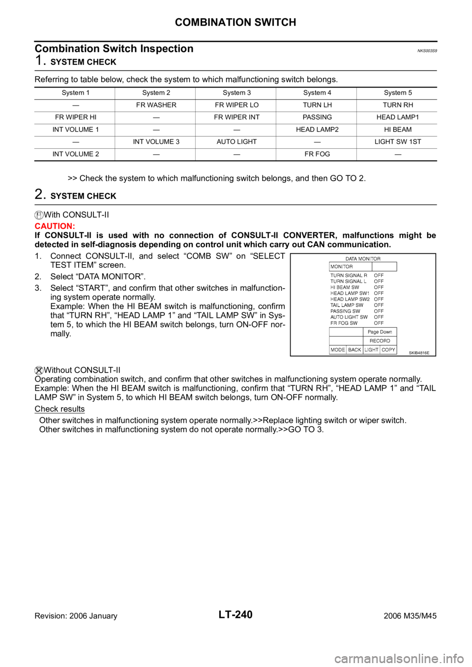
1. Connect CONSULT-II, and select “COMB SW” on “SELECT
TEST ITEM” screen.
2. Select “DATA MONITOR”.
3. Select “START”, and confirm that other switches in malfunction-
ing system operate normally.
Example: When the HI BEAM switch is malfunctioning, confirm
that “TURN RH”, “HEAD LAMP 1” and “TAIL LAMP SW” in Sys-
tem 5, to which the HI BEAM switch belongs, turn ON-OFF nor-
mally.
Without CONSULT-II
Operating combination switch, and confirm that other switches in malfunctioning system operate normally.
Example: When the HI BEAM switch is malfunctioning, confirm that “TURN RH”, “HEAD LAMP 1” and “TAIL
LAMP SW” in System 5, to which HI BEAM switch belongs, turn ON-OFF normally.
Check results
Other switches in malfunctioning system operate normally.>>Replace lighting switch or wiper switch.
Other switches in malfunctioning system do not operate normally.>>GO TO 3.
System 1 System 2 System 3 System 4 System 5
— FR WASHER FR WIPER LO TURN LH TURN RH
FR WIPER HI — FR WIPER INT PASSING HEAD LAMP1
INT VOLUME 1 — — HEAD LAMP2 HI BEAM
— INT VOLUME 3 AUTO LIGHT — LIGHT SW 1ST
INT VOLUME 2 — — FR FOG —
SKIB4816E
Page 4668 of 5621
COMBINATION SWITCH
LT-241
C
D
E
F
G
H
I
J
L
MA
B
LT
Revision: 2006 January2006 M35/M45
3. CHECK HARNESS
1. Turn ignition switch OFF.
2. Disconnect BCM and combination switch connectors.
3. Check for continuity between BCM harness connector (A) of the suspect system and the corresponding
combination switch connector (B).
4. Check for continuity between each of BCM harness connector in suspect malfunctioning system and
ground.
OK or NG
OK >> GO TO 4.
NG >> Check harness between BCM and combination switch for open or short circuit.
Sus-
pect
systemAB
Continuity
Connector Terminal Connector Terminal
1
M1Input 1 6
M296
Ye s Output 1 36 1
2Input 2 5 7
Output 2 35 2
3Input 3 4 10
Output 3 34 3
4Input 4 3 9
Output 4 33 4
5Input 5 2 8
Output 5 32 5
Suspect
systemBCM
connectorTerminal
GroundContinuity
1
M1Input 1 6
No Output 1 36
2Input 2 5
Output 2 35
3Input 3 4
Output 3 34
4Input 4 3
Output 4 33
5Input 5 2
Output 5 32
SKIB4819E
PKIA7506E
Page 4669 of 5621
LT-242
COMBINATION SWITCH
Revision: 2006 January2006 M35/M45
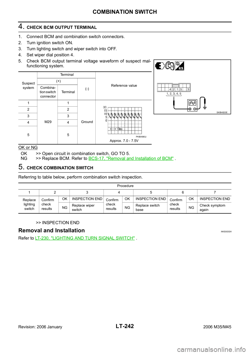
4. CHECK BCM OUTPUT TERMINAL
1. Connect BCM and combination switch connectors.
2. Turn ignition switch ON.
3. Turn lighting switch and wiper switch into OFF.
4. Set wiper dial position 4.
5. Check BCM output terminal voltage waveform of suspect mal-
functioning system.
OK or NG
OK >> Open circuit in combination switch, GO TO 5.
NG >> Replace BCM. Refer to BCS-17, "
Removal and Installation of BCM" .
5. CHECK COMBINATION SWITCH
Referring to table below, perform combination switch inspection.
>> INSPECTION END
Removal and InstallationNKS003SA
Refer to LT- 2 3 0 , "LIGHTING AND TURN SIGNAL SWITCH" .
Suspect
systemTerminal
Reference value (+)
(-) Combina-
tion switch
connectorTerminal
1
M291
Ground
Approx. 7.0 - 7.5V 22
33
44
55
SKIB4820E
PKIB4960J
Procedure
12 34567
Replace
lighting
switchConfirm
check
resultsOK INSPECTION END
Confirm
check
resultsOK INSPECTION END
Confirm
check
resultsOK INSPECTION END
NGReplace wiper
switchNGReplace switch
baseNGCheck symptom
again
Page 4684 of 5621
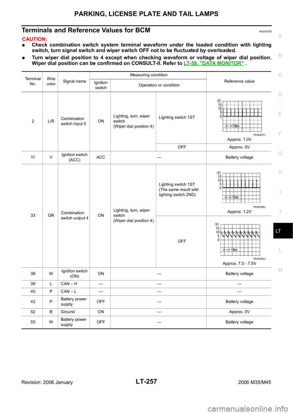
PARKING, LICENSE PLATE AND TAIL LAMPS
LT-257
C
D
E
F
G
H
I
J
L
MA
B
LT
Revision: 2006 January2006 M35/M45
Terminals and Reference Values for BCMNKS003SN
CAUTION:
Check combination switch system terminal waveform under the loaded condition with lighting
switch, turn signal switch and wiper switch OFF not to be fluctuated by overloaded.
Turn wiper dial position to 4 except when checking waveform or voltage of wiper dial position.
Wiper dial position can be confirmed on CONSULT-II. Refer to LT- 5 8 , "
DATA MONITOR" .
Terminal
No.Wire
colorSignal nameMeasuring condition
Reference value
Ignition
switchOperation or condition
2L/RCombination
switch input 5ONLighting, turn, wiper
switch
(Wiper dial position 4)Lighting switch 1ST
Approx. 1.0V
OFF Approx. 0V
11 VIgnition switch
(ACC)ACC — Battery voltage
33 GRCombination
switch output 4ONLighting, turn, wiper
switch
(Wiper dial position 4)Lighting switch 1ST
(The same result with
lighting switch 2ND)
Approx. 1.2V
OFF
Approx. 7.0 - 7.5V
38 WIgnition switch
(ON) ON — Battery voltage
39 L CAN
H — — —
40 P CAN
L — — —
42 PBattery power
supplyOFF — Battery voltage
52 B Ground ON — Approx. 0V
55 WBattery power
supplyOFF — Battery voltage
PKIB4957J
PKIB4958J
PKIB4960J