2006 INFINITI M35 check
[x] Cancel search: checkPage 4711 of 5621
LT-284
INTERIOR ROOM LAMP
Revision: 2006 January2006 M35/M45
CONSULT-II Functions (BCM)NKS003T7
CONSULT-II can display each diagnostic item using the diagnostic test modes shown following.
CONSULT-II BASIC OPERATION
CAUTION:
If CONSULT-II is used with no connection of CONSULT-II CONVERTER, malfunctions might be
detected in self-diagnosis depending on control unit which carry out CAN communication.
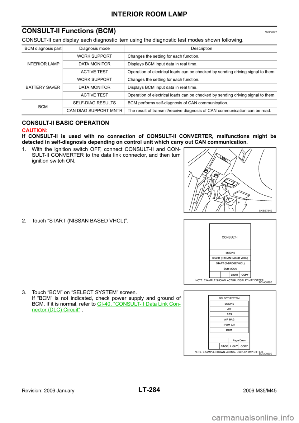
1. With the ignition switch OFF, connect CONSULT-II and CON-
SULT-II CONVERTER to the data link connector, and then turn
ignition switch ON.
2. Touch “START (NISSAN BASED VHCL)”.
3. Touch “BCM” on “SELECT SYSTEM” screen.
If “BCM” is not indicated, check power supply and ground of
BCM. If it is normal, refer to GI-40, "
CONSULT-II Data Link Con-
nector (DLC) Circuit" .
BCM diagnosis part Diagnosis mode Description
INTERIOR LAMPWORK SUPPORT Changes the setting for each function.
DATA MONITOR Displays BCM input data in real time.
ACTIVE TEST Operation of electrical loads can be checked by sending driving signal to them.
BATTERY SAVERWORK SUPPORT Changes the setting for each function.
DATA MONITOR Displays BCM input data in real time.
ACTIVE TEST Operation of electrical loads can be checked by sending driving signal to them.
BCMSELF-DIAG RESULTS BCM performs self-diagnosis of CAN communication.
CAN DIAG SUPPORT MNTR The result of transmit/receive diagnosis of CAN communication can be read.
SKIB3794E
BCIA0029E
BCIA0030E
Page 4714 of 5621
INTERIOR ROOM LAMP
LT-287
C
D
E
F
G
H
I
J
L
MA
B
LT
Revision: 2006 January2006 M35/M45
ACTIVE TEST (INT LAMP)
Operation Procedure
1. Touch “INT LAMP” on “SELECT TEST ITEM” screen.
2. Touch “ACTIVE TEST” on “SELECT DIAG MODE” screen.
3. Touch item to be tested and check operation of the selected item.
4. During the operation check, touching “BACK” deactivates the operation.
Display Item List
WORK SUPPORT (BATTERY SAVER)
Operation procedure
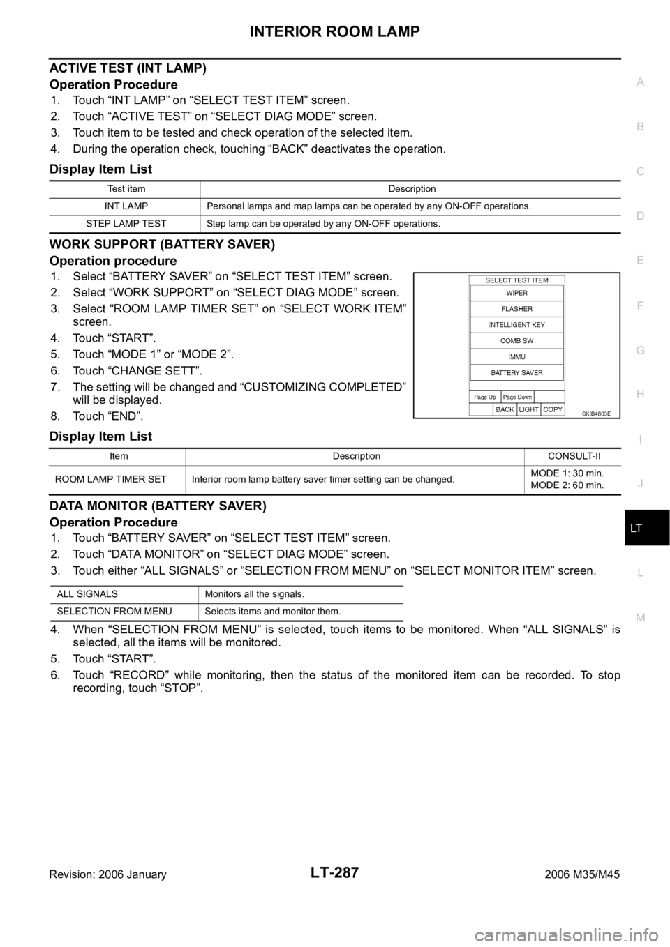
1. Select “BATTERY SAVER” on “SELECT TEST ITEM” screen.
2. Select “WORK SUPPORT” on “SELECT DIAG MODE” screen.
3. Select “ROOM LAMP TIMER SET” on “SELECT WORK ITEM”
screen.
4. Touch “START”.
5. Touch “MODE 1” or “MODE 2”.
6. Touch “CHANGE SETT”.
7. The setting will be changed and “CUSTOMIZING COMPLETED”
will be displayed.
8. Touch “END”.
Display Item List
DATA MONITOR (BATTERY SAVER)
Operation Procedure
1. Touch “BATTERY SAVER” on “SELECT TEST ITEM” screen.
2. Touch “DATA MONITOR” on “SELECT DIAG MODE” screen.
3. Touch either “ALL SIGNALS” or “SELECTION FROM MENU” on “SELECT MONITOR ITEM” screen.
4. When “SELECTION FROM MENU” is selected, touch items to be monitored. When “ALL SIGNALS” is
selected, all the items will be monitored.
5. Touch “START”.
6. Touch “RECORD” while monitoring, then the status of the monitored item can be recorded. To stop
recording, touch “STOP”.
Test item Description
INT LAMP Personal lamps and map lamps can be operated by any ON-OFF operations.
STEP LAMP TEST Step lamp can be operated by any ON-OFF operations.
SKIB4803E
Item Description CONSULT-II
ROOM LAMP TIMER SET Interior room lamp battery saver timer setting can be changed.MODE 1: 30 min.
MODE 2: 60 min.
ALL SIGNALS Monitors all the signals.
SELECTION FROM MENU Selects items and monitor them.
Page 4715 of 5621

LT-288
INTERIOR ROOM LAMP
Revision: 2006 January2006 M35/M45
Display Item List
NOTE:
This item is displayed, but cannot be monitored.
ACTIVE TEST (BATTERY SAVER)
Operation Procedure
1. Touch “BATTERY SAVER” on “SELECT TEST ITEM” screen.
2. Touch “ACTIVE TEST” on “SELECT DIAG MODE” screen.
3. Touch item to be tested and check operation of the selected item.
4. During the operation check, touching “BACK” deactivates the operation.
Display Item List
Monitor item Contents
IGN ON SW “ON/OFF”Displays “IGN ON position (ON)/OFF, ACC position (OFF)” judged from the ignition switch
signal.
ACC ON SW “ON/OFF”Displays “IGN ACC, ON position (ON)/OFF position (OFF)” status judged from the key
switch signal.
KEY ON SW “ON/OFF”Displays “Intelligent Key inserted into key slot (ON)/Intelligent Key removed from key slot
(OFF)” status judged from the key switch signal.
DOOR SW - DR “ON/OFF”Displays status of the driver door as judged from the driver door switch signal. (door is open:
ON/door is closed: OFF)
DOOR SW - AS “ON/OFF”Displays “door open (ON)/door closed (OFF)” status, determined from passenger door
switch signal.
DOOR SW - RR “ON/OFF”Displays “door open (ON)/door closed (OFF)” status, determined from rear door switch RH
signal.
DOOR SW - RL “ON/OFF”Displays “door open (ON)/door closed (OFF) ” status, determined from rear door switch LH
signal.
BACK DOOR SW
NOTE“OFF” —
CDL LOCK SW “ON/OFF”Displays “door locked (ON)/other (OFF) status, determined from central door lock switch
LOCK signal.
CDL UNLOCK SW “ON/OFF”Displays “door unlocked (ON)/other (OFF)” status, determined from central door lock switch
UNLOCK signal.
KEY CYL LK – SW “ON/OFF” Displays “door locked (ON)” status, determined from key cylinder switch in driver door.
KEY CYL UN – SW “ON/OFF” Displays “door unlocked (OFF)” status, determined from key cylinder switch in driver door.
I - KEY LOCK “ON/OFF” Displays “locked (ON)/other (OFF)” status, determined from lock signal.
I - KEY UNLOCK “ON/OFF” Displays “unlocked (ON)/other (OFF)” status, determined from unlock signal.
TRNK/HAT MNTR “ON/OFF”Displays “trunk open (ON)/trunk close (OFF)” status, determined from trunk room lamp
switch.
I - KEY DR UNLK “ON/OFF”Displays “ON” when only driver door is unlocked or “OFF” other cases by Intelligent Key or
any door request switch, determined from unlock signal.
I - KEY AS UNLK “ON/OFF”Displays “unlocked (ON)/locked (OFF)” states of passenger door by passenger side door
request switch, determined from unlock signal.
Test item Description
BATTERY SAVER Personal lamps and map lamps can be operated by any ON-OFF operations.
Page 4716 of 5621
INTERIOR ROOM LAMP
LT-289
C
D
E
F
G
H
I
J
L
MA
B
LT
Revision: 2006 January2006 M35/M45
Interior Room Lamp Control Does Not OperateNKS003T8
1. SELF-DIAGNOSIS
With CONSULT-II
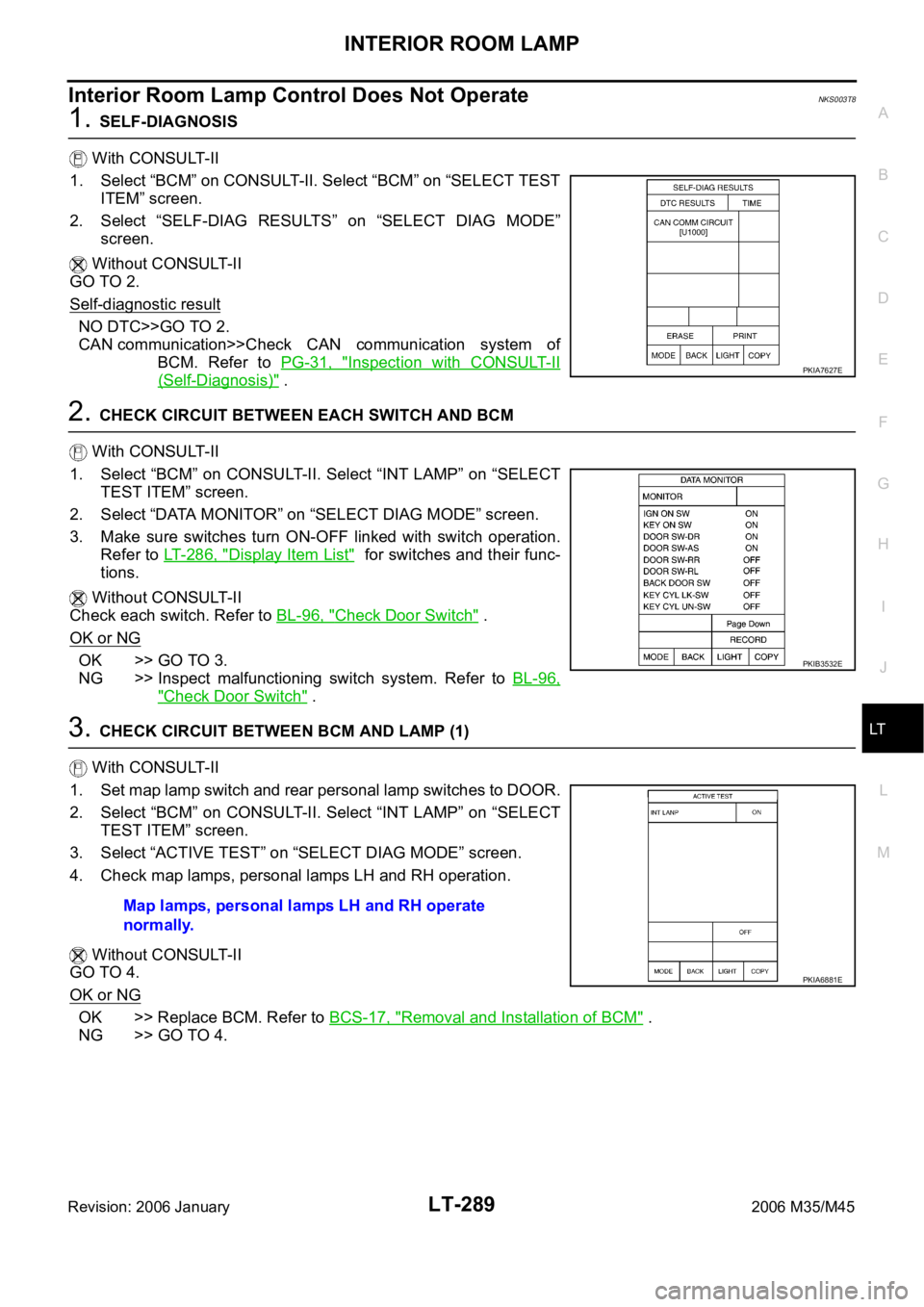
1. Select “BCM” on CONSULT-II. Select “BCM” on “SELECT TEST
ITEM” screen.
2. Select “SELF-DIAG RESULTS” on “SELECT DIAG MODE”
screen.
Without CONSULT-II
GO TO 2.
Self-diagnostic result
NO DTC>>GO TO 2.
CAN communication>>Check CAN communication system of
BCM. Refer to PG-31, "
Inspection with CONSULT-II
(Self-Diagnosis)" .
2. CHECK CIRCUIT BETWEEN EACH SWITCH AND BCM
With CONSULT-II
1. Select “BCM” on CONSULT-II. Select “INT LAMP” on “SELECT
TEST ITEM” screen.
2. Select “DATA MONITOR” on “SELECT DIAG MODE” screen.
3. Make sure switches turn ON-OFF linked with switch operation.
Refer to LT- 2 8 6 , "
Display Item List" for switches and their func-
tions.
Without CONSULT-II
Check each switch. Refer to BL-96, "
Check Door Switch" .
OK or NG
OK >> GO TO 3.
NG >> Inspect malfunctioning switch system. Refer to BL-96,
"Check Door Switch" .
3. CHECK CIRCUIT BETWEEN BCM AND LAMP (1)
With CONSULT-II
1. Set map lamp switch and rear personal lamp switches to DOOR.
2. Select “BCM” on CONSULT-II. Select “INT LAMP” on “SELECT
TEST ITEM” screen.
3. Select “ACTIVE TEST” on “SELECT DIAG MODE” screen.
4. Check map lamps, personal lamps LH and RH operation.
Without CONSULT-II
GO TO 4.
OK or NG
OK >> Replace BCM. Refer to BCS-17, "Removal and Installation of BCM" .
NG >> GO TO 4.
PKIA7627E
PKIB3532E
Map lamps, personal lamps LH and RH operate
normally.
PKIA6881E
Page 4717 of 5621
LT-290
INTERIOR ROOM LAMP
Revision: 2006 January2006 M35/M45
4. CHECK CIRCUIT BETWEEN BCM AND MAP LAMP (2)
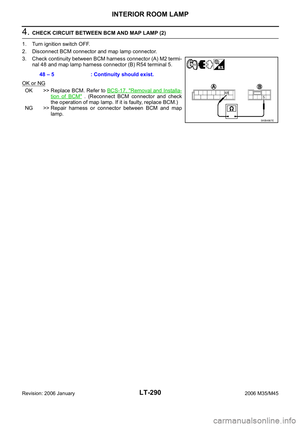
1. Turn ignition switch OFF.
2. Disconnect BCM connector and map lamp connector.
3. Check continuity between BCM harness connector (A) M2 termi-
nal 48 and map lamp harness connector (B) R54 terminal 5.
OK or NG
OK >> Replace BCM. Refer to BCS-17, "Removal and Installa-
tion of BCM" . (Reconnect BCM connector and check
the operation of map lamp. If it is faulty, replace BCM.)
NG >> Repair harness or connector between BCM and map
lamp. 48 – 5 : Continuity should exist.
SKIB4867E
Page 4744 of 5621
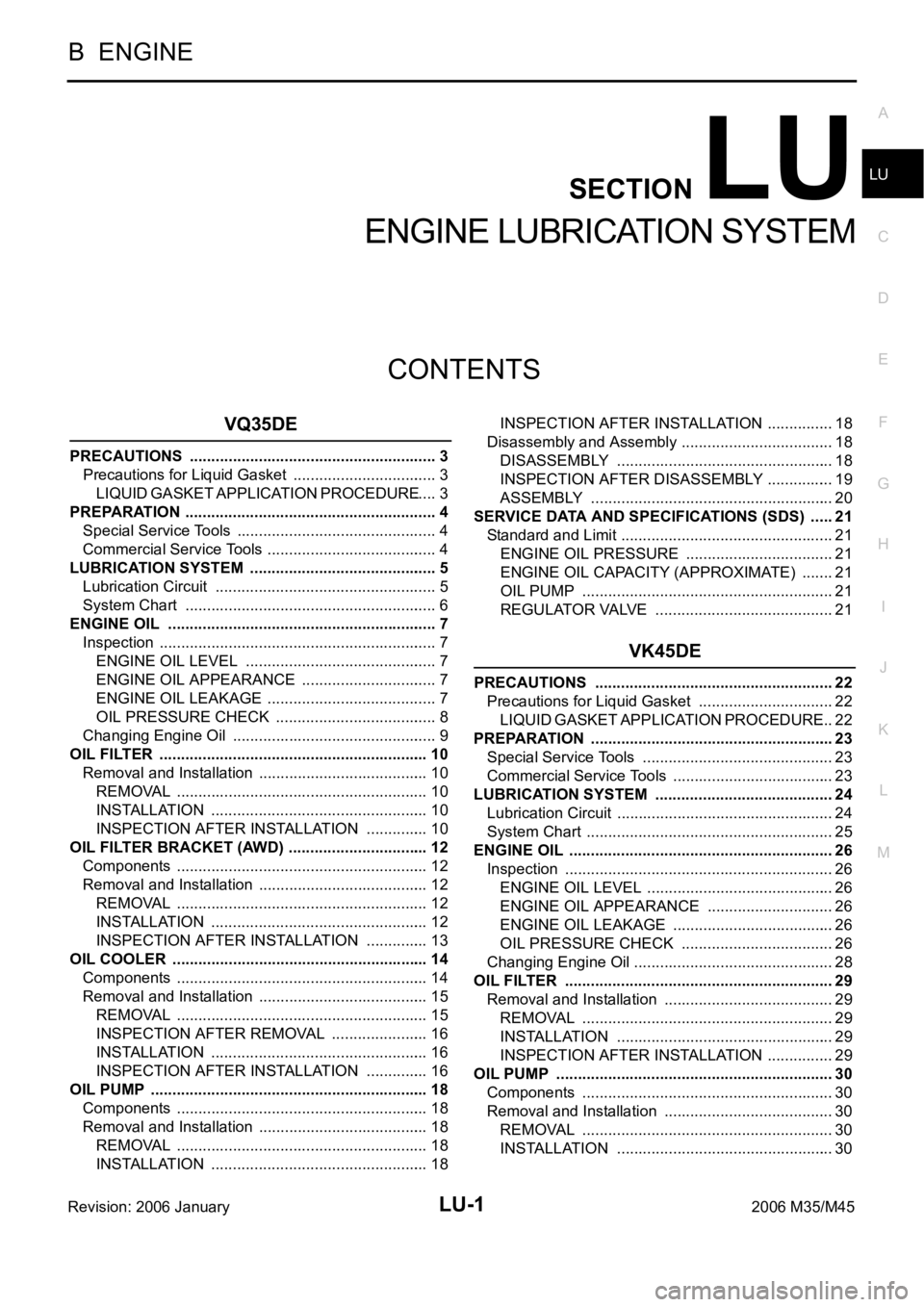
LU-1
ENGINE LUBRICATION SYSTEM
B ENGINE
CONTENTS
C
D
E
F
G
H
I
J
K
L
M
SECTION LU
A
LU
Revision: 2006 January2006 M35/M45
ENGINE LUBRICATION SYSTEM
VQ35DE
PRECAUTIONS .......................................................... 3
Precautions for Liquid Gasket .................................. 3
LIQUID GASKET APPLICATION PROCEDURE ..... 3
PREPARATION ........................................................... 4
Special Service Tools ............................................... 4
Commercial Service Tools ........................................ 4
LUBRICATION SYSTEM ............................................ 5
Lubrication Circuit .................................................... 5
System Chart ........................................................... 6
ENGINE OIL ............................................................... 7
Inspection ................................................................. 7
ENGINE OIL LEVEL ............................................. 7
ENGINE OIL APPEARANCE ................................ 7
ENGINE OIL LEAKAGE ........................................ 7
OIL PRESSURE CHECK ...................................... 8
Changing Engine Oil ................................................ 9
OIL FILTER ............................................................... 10
Removal and Installation ........................................ 10
REMOVAL ........................................................
... 10
INSTALLATION ................................................... 10
INSPECTION AFTER INSTALLATION ............... 10
OIL FILTER BRACKET (AWD) ................................. 12
Components ........................................................... 12
Removal and Installation ........................................ 12
REMOVAL ........................................................
... 12
INSTALLATION ................................................... 12
INSPECTION AFTER INSTALLATION ............... 13
OIL COOLER ............................................................ 14
Components ........................................................... 14
Removal and Installation ........................................ 15
REMOVAL ........................................................
... 15
INSPECTION AFTER REMOVAL ....................... 16
INSTALLATION ................................................... 16
INSPECTION AFTER INSTALLATION ............... 16
OIL PUMP ................................................................. 18
Components ........................................................... 18
Removal and Installation ........................................ 18
REMOVAL ........................................................
... 18
INSTALLATION ................................................... 18INSPECTION AFTER INSTALLATION ................ 18
Disassembly and Assembly .................................... 18
DISASSEMBLY ................................................... 18
INSPECTION AFTER DISASSEMBLY ................ 19
ASSEMBLY ......................................................... 20
SERVICE DATA AND SPECIFICATIONS (SDS) ...... 21
Standard and Limit .................................................. 21
ENGINE OIL PRESSURE ................................... 21
ENGINE OIL CAPACITY (APPROXIMATE) ........ 21
OIL PUMP ........................................................... 21
REGULATOR VALVE .......................................... 21
VK45DE
PRECAUTIONS ........................................................ 22
Precautions for Liquid Gasket ................................ 22
LIQUID GASKET APPLICATION PROCEDURE ... 22
PREPARATION ......................................................... 23
Special Service Tools ............................................. 23
Commercial Service Tools ...................................... 23
LUBRICATION SYSTEM .......................................... 24
Lubrication Circuit ................................................... 24
System Chart .......................................................... 25
ENGINE OIL .............................................................. 26
Inspection ............................................................... 26
ENGINE OIL LEVEL ............................................ 26
ENGINE OIL APPEARANCE .............................. 26
ENGINE OIL LEAKAGE ...................................... 26
OIL PRESSURE CHECK .................................... 26
Changing Engine Oil ............................................
... 28
OIL FILTER ............................................................... 29
Removal and Installation ........................................ 29
REMOVAL ........................................................
... 29
INSTALLATION ................................................... 29
INSPECTION AFTER INSTALLATION ................ 29
OIL PUMP ................................................................. 30
Components ........................................................... 30
Removal and Installation ........................................ 30
REMOVAL ........................................................
... 30
INSTALLATION ................................................... 30
Page 4750 of 5621
![INFINITI M35 2006 Factory Service Manual ENGINE OIL
LU-7
[VQ35DE]
C
D
E
F
G
H
I
J
K
L
MA
LU
Revision: 2006 January2006 M35/M45
ENGINE OILPFP:KLA92
InspectionNBS004PW
ENGINE OIL LEVEL
NOTE:
Before starting engine, put vehicle horizontally and INFINITI M35 2006 Factory Service Manual ENGINE OIL
LU-7
[VQ35DE]
C
D
E
F
G
H
I
J
K
L
MA
LU
Revision: 2006 January2006 M35/M45
ENGINE OILPFP:KLA92
InspectionNBS004PW
ENGINE OIL LEVEL
NOTE:
Before starting engine, put vehicle horizontally and](/manual-img/42/57023/w960_57023-4749.png)
ENGINE OIL
LU-7
[VQ35DE]
C
D
E
F
G
H
I
J
K
L
MA
LU
Revision: 2006 January2006 M35/M45
ENGINE OILPFP:KLA92
InspectionNBS004PW
ENGINE OIL LEVEL
NOTE:
Before starting engine, put vehicle horizontally and check the engine oil level. If engine is already started, stop
it and allow 10 minutes before checking.
1. Pull out oil level gauge and wipe it clean.
2. Insert oil level gauge and make sure the engine oil level is within
the range shown in the figure.
3. If it is out of range, adjust it.
NOTE:
When checking the engine oil level, insert oil level gauge with its
tip aligned with oil level gauge guide on cylinder head. (In figure,
air cleaner case and air duct are removed.)
ENGINE OIL APPEARANCE
Check engine oil for white turbidity or heavy contamination.
If engine oil becomes turbid and white, it is highly probable that it is contaminated with engine coolant.
Repair or replace damaged parts.
ENGINE OIL LEAKAGE
Check for engine oil leakage around the following areas:
Oil pans (lower and upper)
Oil pan drain plug
Oil pressure switch
Oil filter
Oil filter bracket (AWD models)
Oil cooler
Water pump cover
Chain tensioner cover
Intake valve timing control cover and intake valve timing control solenoid valve
Mating surface between cylinder head and rocker cover
Mating surface between front timing chain case and rear timing chain case
Mating surface between rear timing chain case and cylinder head
Mating surface between rear timing chain case and cylinder block
Mating surface between rear timing chain case and oil pan (upper)
Mating surface between cylinder block and cylinder head
PBIC0249E
KBIA1343E
Page 4751 of 5621
![INFINITI M35 2006 Factory Service Manual LU-8
[VQ35DE]
ENGINE OIL
Revision: 2006 January2006 M35/M45
Crankshaft oil seals (front and rear)
Camshaft position sensor (PHASE)
OIL PRESSURE CHECK
WAR NING :
Be careful not to get burn yourself, as INFINITI M35 2006 Factory Service Manual LU-8
[VQ35DE]
ENGINE OIL
Revision: 2006 January2006 M35/M45
Crankshaft oil seals (front and rear)
Camshaft position sensor (PHASE)
OIL PRESSURE CHECK
WAR NING :
Be careful not to get burn yourself, as](/manual-img/42/57023/w960_57023-4750.png)
LU-8
[VQ35DE]
ENGINE OIL
Revision: 2006 January2006 M35/M45
Crankshaft oil seals (front and rear)
Camshaft position sensor (PHASE)
OIL PRESSURE CHECK
WAR NING :
Be careful not to get burn yourself, as engine oil may be hot.
Oil pressure check should be done in “Parking position”.
1. Check the engine oil level. Refer to LU-7, "
ENGINE OIL LEVEL" .
2. Remove front engine undercover with power tool.
3. Disconnect harness connector at oil pressure switch, and
remove oil pressure switch using deep socket (commercial ser-
vice tool).
CAUTION:
Do not drop or shock oil pressure switch.
Remove the oil pressure switch using a 26 mm (1.02 in) box
wrench. (AWD models)
4. Install the oil pressure gauge (SST) and hose (SST).
5. Start the engine and warm it up to normal operating temperature.
6. Check the engine oil pressure with engine running under no-load.
NOTE:
When the engine oil temperature is low, the engine oil pressure becomes high.
Engine oil pressure [Engine oil temperature at 80
C (176 F)]
If difference is extreme, check engine oil passage and oil pump for engine oil leaks.
7. After the inspections, install oil pressure switch as follows:
SBIA0452E
SBIA0453E
SLC926
Engine speed (rpm)
Approximate discharge pressure [kPa (kg/cm2 , psi)]
Idle speed More than 98 (1.0, 14)
2,000 More than 294 (3.0, 43)