2006 INFINITI M35 Rear suspension
[x] Cancel search: Rear suspensionPage 3434 of 5621
![INFINITI M35 2006 Factory Service Manual FRONT SUSPENSION ASSEMBLY
FSU-7
[2WD]
C
D
F
G
H
I
J
K
L
MA
B
FSU
Revision: 2006 January2006 M35/M45
THE ALIGNMENT PROCESS
IMPORTANT:
Use only the alignment specifications listed in this Service Manual INFINITI M35 2006 Factory Service Manual FRONT SUSPENSION ASSEMBLY
FSU-7
[2WD]
C
D
F
G
H
I
J
K
L
MA
B
FSU
Revision: 2006 January2006 M35/M45
THE ALIGNMENT PROCESS
IMPORTANT:
Use only the alignment specifications listed in this Service Manual](/manual-img/42/57023/w960_57023-3433.png)
FRONT SUSPENSION ASSEMBLY
FSU-7
[2WD]
C
D
F
G
H
I
J
K
L
MA
B
FSU
Revision: 2006 January2006 M35/M45
THE ALIGNMENT PROCESS
IMPORTANT:
Use only the alignment specifications listed in this Service Manual.
When displaying the alignment settings, many alignment machines use “indicators”: (Green/red, plus or
minus, Go/No Go). Do NOT use these indicators.
–The alignment specifications programmed into your machine that operate these indicators may not be cor-
rect.
–This may result in an ERROR.
Some newer alignment machines are equipped with an optional “Rolling Compensation” method to “com-
pensate” the sensors (alignment targets or head units). DO NOT use this “Rolling Compensation”
method.
–Use the “Jacking Compensation Method”. After installing the alignment targets or head units, raise the
vehicle and rotate the wheels 1/2 turn both ways.
–See Instructions in the alignment machine you're using for more information on this.
INSPECTION OF CAMBER, CASTER AND KINGPIN INCLINATION ANGLES
Camber, caster, kingpin inclination angles cannot be adjusted.
Before inspection, mount front wheels onto turning radius gauge. Mount rear wheels onto a stand that has
same height so vehicle will remain horizontal.
Using a CCK Gauge
Install the CCK gauge attachment [SST: KV991040S0 ( – )] with the following procedure on wheel, then
measure wheel alignment.
1. Remove three wheel nuts, and install the guide bolts to hub bolt.
2. Screw the adapter into the plate until it contacts the plate tightly.
3. Screw the center plate into the plate.
4. Insert the plate assembly on the guide bolt. Put the spring in,
and then evenly screw the three guide bolt nuts. When fastening
the guide nuts, do not completely compress the spring.
5. Place the dent of alignment gauge onto the projection of the
center plate and tightly contact them to measure.
CAUTION:
If camber, caster, or kingpin inclination angle is outside
the standard, check front suspension parts for wear and
damage. Replace suspect parts if a malfunction is
detected.
Kingpin inclination angle is reference value, no inspec-
tion is required.
SEIA0240E
Camber, caster, kingpin inclination angles:
Refer to FSU-19, "
SERVICE DATA AND SPECIFICA-
TIONS (SDS)" .
SEIA0241E
Page 3451 of 5621
![INFINITI M35 2006 Factory Service Manual FSU-24
[AWD]
FRONT SUSPENSION ASSEMBLY
Revision: 2006 January2006 M35/M45
THE ALIGNMENT PROCESS
IMPORTANT:
Use only the alignment specifications listed in this Service Manual.
When displaying the a INFINITI M35 2006 Factory Service Manual FSU-24
[AWD]
FRONT SUSPENSION ASSEMBLY
Revision: 2006 January2006 M35/M45
THE ALIGNMENT PROCESS
IMPORTANT:
Use only the alignment specifications listed in this Service Manual.
When displaying the a](/manual-img/42/57023/w960_57023-3450.png)
FSU-24
[AWD]
FRONT SUSPENSION ASSEMBLY
Revision: 2006 January2006 M35/M45
THE ALIGNMENT PROCESS
IMPORTANT:
Use only the alignment specifications listed in this Service Manual.
When displaying the alignment settings, many alignment machines use “indicators”: (Green/red, plus or
minus, Go/No Go). Do NOT use these indicators.
–The alignment specifications programmed into your machine that operate these indicators may not be cor-
rect.
–This may result in an ERROR.
Some newer alignment machines are equipped with an optional “Rolling Compensation” method to “com-
pensate” the sensors (alignment targets or head units). DO NOT use this “Rolling Compensation”
method.
–Use the “Jacking Compensation Method”. After installing the alignment targets or head units, raise the
vehicle and rotate the wheels 1/2 turn both ways.
–See Instructions in the alignment machine you're using for more information on this.
INSPECTION OF CAMBER, CASTER AND KINGPIN INCLINATION ANGLES
Camber, caster, kingpin inclination angles cannot be adjusted.
Before inspection, mount front wheels onto turning radius gauge. Mount rear wheels onto a stand that has
same height so vehicle will remain horizontal.
Using a CCK Gauge
Install the CCK gauge attachment [SST: KV991040S0 ( – )] with the following procedure on wheel, then
measure wheel alignment.
1. Remove three wheel nuts, and install the guide bolts to hub bolt.
2. Screw the adapter into the plate until it contacts the plate tightly.
3. Screw the center plate into the plate.
4. Insert the plate assembly on the guide bolt. Put the spring in,
and then evenly screw the three guide bolt nuts. When fastening
the guide nuts, do not completely compress the spring.
5. Place the dent of alignment gauge onto the projection of the
center plate and tightly contact them to measure.
CAUTION:
If camber, caster, or kingpin inclination angle is outside
the standard, check front suspension parts for wear and
damage. Replace suspect parts if a malfunction is
detected.
Kingpin inclination angle is reference value, no inspec-
tion is required.
SEIA0240E
Camber, caster, kingpin inclination angles:
Refer to FSU-36, "
SERVICE DATA AND SPECIFICA-
TIONS (SDS)" .
SEIA0241E
Page 3505 of 5621
GI-42
LIFTING POINT
Revision: 2006 January2006 M35/M45
LIFTING POINTPFP:00000
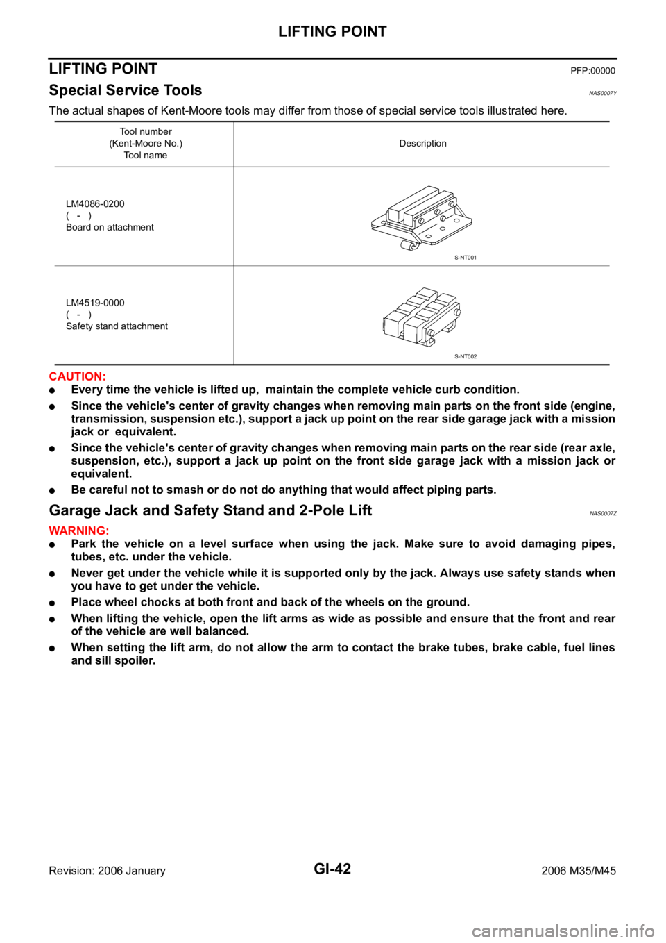
Special Service Tools NAS0007Y
The actual shapes of Kent-Moore tools may differ from those of special service tools illustrated here.
CAUTION:
Every time the vehicle is lifted up, maintain the complete vehicle curb condition.
Since the vehicle's center of gravity changes when removing main parts on the front side (engine,
transmission, suspension etc.), support a jack up point on the rear side garage jack with a mission
jack or equivalent.
Since the vehicle's center of gravity changes when removing main parts on the rear side (rear axle,
suspension, etc.), support a jack up point on the front side garage jack with a mission jack or
equivalent.
Be careful not to smash or do not do anything that would affect piping parts.
Garage Jack and Safety Stand and 2-Pole LiftNAS0007Z
WAR NING :
Park the vehicle on a level surface when using the jack. Make sure to avoid damaging pipes,
tubes, etc. under the vehicle.
Never get under the vehicle while it is supported only by the jack. Always use safety stands when
you have to get under the vehicle.
Place wheel chocks at both front and back of the wheels on the ground.
When lifting the vehicle, open the lift arms as wide as possible and ensure that the front and rear
of the vehicle are well balanced.
When setting the lift arm, do not allow the arm to contact the brake tubes, brake cable, fuel lines
and sill spoiler.
Tool number
(Kent-Moore No.)
Tool nameDescription
LM4086-0200
( - )
Board on attachment
LM4519-0000
( - )
Safety stand attachment
S-NT001
S-NT002
Page 3508 of 5621
TOW TRUCK TOWING
GI-45
C
D
E
F
G
H
I
J
K
L
MB
GI
Revision: 2006 January2006 M35/M45
AWD MODELS
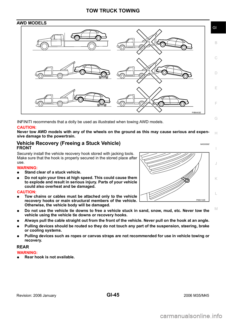
INFINITI recommends that a dolly be used as illustrated when towing AWD models.
CAUTION:
Never tow AWD models with any of the wheels on the ground as this may cause serious and expen-
sive damage to the powertrain.
Vehicle Recovery (Freeing a Stuck Vehicle) NAS00082
FRONT
Securely install the vehicle recovery hook stored with jacking tools.
Make sure that the hook is properly secured in the stored place after
use.
WAR NING :
Stand clear of a stuck vehicle.
Do not spin your tires at high speed. This could cause them
to explode and result in serious injury. Parts of your vehicle
could also overheat and be damaged.
CAUTION:
Tow chains or cables must be attached only to the vehicle
recovery hooks or main structural members of the vehicle.
Otherwise, the vehicle body will be damaged.
Do not use the vehicle tie downs to free a vehicle stuck in sand, snow, mud, etc. Never tow the
vehicle using the vehicle tie downs or recovery hooks.
Always pull the cable straight out from the front of the vehicle. Never pull on the hook at an angle.
Pulling devices should be routed so they do not touch any part of the suspension, steering, brake
or cooling systems.
Pulling devices such as ropes or canvas straps are not recommended for use in vehicle towing or
recovery.
REAR
WAR NING :
Rear hook is not available.
PIIB6403E
PIIB3130E
Page 3648 of 5621
IDX-7
A
C
D
E
F
G
H
I
J
K
L B
IDX
ALPHABETICAL INDEX
LT-266
Rear disc brake ................................................. BR-29
Rear door ............................................ BL-190, GW-67
Rear parcel shelf finisher ..................................... EI-42
Rear seat ......................................................... SE-172
Rear seat belt .................................................... SB-32
Rear suspension ............................................... RSU-5
Rear window ..................................................... GW-61
Rear window defogger ...................................... GW-73
Refrigerant connection precaution ..................... ATC-7
Refrigerant discharging evacuating charging ATC-151
Refrigerant general precaution .......................... ATC-7
Refrigerant lines ............................................ ATC-151
Refrigerant pressure sensor ........... EC-692, EC-1434,
ATC-98
, ATC-167
Refrigeration cycle ........................................... ATC-20
Removal and installation (A/T) ........... AT-271, AT-275
Removal and installation (Transfer) .................... TF-44
Reverse interlock door mirror ........................... GW-96
Revolution sensor (A/T) ...................... AT-119, AT-261
Rocker cover(VK45DE) ................................... EM-199
Rocker cover(VQ35DE) ..................................... EM-51
Room lamp - See Interior lamp ......................... LT-267
ROOM/L - Wiring diagram ................................ LT-274
RP/SEN - Wiring diagram ................ EC-693, EC-1435
S
SAE J1979 - Service $01 - 09 ............. EC-54
, EC-764
SEAT - Wiring diagram ...................................... SE-98
Seat belt inspection ........................................... SB-33
Seat belt, front ................................................... SB-30
Seat belt, rear .................................................... SB-32
Seat, rear ......................................................... SE-172
Self-diagnosis (Transfer) .................................... TF-22
SEN/PW - Wiring diagram ............... EC-500, EC-1219
SHIFT - Wiring diagram ................................... AT-230
Shift lock system .............................................. AT-229
Shock absorber (rear) ..................................... RSU-10
Side air bag (satellite) sensor .......................... SRS-46
Side curtain air bag .......................................... SRS-43
Side trim .............................................................. EI-37
SMJ (super multiple junction) .......................... PG-106
Spark plug replacement ..................................... MA-27
Spark plug replacement(VQ35DE) .................... MA-20
Spark plug(VK45DE) ....................................... EM-191
Spark plug(VQ35DE) ......................................... EM-43
Specification value ............................. EC-155, EC-868
Speedometer ........................................................ DI-5
Spiral cable ...................................................... SRS-40
SROOF - Wiring diagram .................................. RF-13
SRS - See Supplemental Restraint System ...... SRS-5
SRS - Wiring diagram ...................................... SRS-12
SRS Trouble diagnoses ..................................... SRS-8
Stabilizer bar (rear) ......................................... RSU-17
Stall test (A/T) .................................................... AT-53
Standardized relay ........................................... PG-109
START - Wiring diagram ................................... SC-11
Starter ................................................................ SC-10
Starting system .................................................. SC-10
Steering gear and linkage inspection ................ MA-36
Steering linkage ................................................. PS-18
Steering wheel and column ................... PS-10, PS-13
Steering wheel turning force .............................. PS-10
Stop lamp .......................................................... LT-243
Stop lamp switch .............................. EC-598, EC-1329
STSIG - Wiring diagram ................................... AT-109
Sun roof, electric ................................................ RF-10
Sunload sensor ............................. ATC-119, ATC-128
Sunroof .................................................. RF-25, RF-28
Sunshade ............................................................ EI-44
Supplemental Restraint System ....................... SRS-5
Supplemental restraint system - Wiring diagram ..........
SRS-12
Suspension ....................................................... MA-37
Symbols and abbreviations ...................... GI-11, GI-24
System readiness test (SRT) code ...... EC-60, EC-770
T
Tachometer ........................................................... DI-5
Tail lamp ........................................................... LT-249
TCM circuit diagram ........................................... AT-52
TCM inspection table ......................................... AT-89
Thermostat(VK45DE) ....................................... CO-55
Thermostat(VQ35DE) ....................................... CO-29
Three way catalyst function (Bank 1) EC-392, EC-1113
Three way catalyst function (Bank 2) EC-392, EC-1113
Three way catalyst precautions ............................ GI-6
Three way catalyst(VK45DE) .......................... EM-183
Throttle control motor ....................... EC-619, EC-1351
Throttle control motor relay .............. EC-607, EC-1338
Throttle position sensor (TPS) .......... EC-231, EC-354,
EC-533
, EC-535, EC-640, EC-954, EC-1077, EC-1259,
EC-1261
, EC-1372
Throttle valve closed position learning . EC-95, EC-806
Tie-rod ............................................................... PS-18
Timing chain(VK45DE) ................................... EM-203
Timing chain(VQ35DE) ..................................... EM-64
Tire rotation ....................................................... MA-35
TLID - Wiring diagram ...................................... BL-211
Top tether strap child restraint ........................... SB-37
Torque converter installation ............. AT-274, AT-277
Torque convertor clutch solenoid valve AT-126, AT-128
TPS1 - Wiring diagram .................... EC-356, EC-1079
TPS2 - Wiring diagram ...................... EC-233, EC-956
TPS3 - Wiring diagram .................... EC-642, EC-1374
Transfer control unit inspection table ................. TF-20
TRNSCV - Wiring diagram ............................... BL-281
Trouble diagnoses .............................................. GI-12
Trunk lid ........................................................... BL-203
Trunk lid opener - See Trunk lid ...................... BL-209
TURN - Wiring diagram .................................... LT-215
Turn signal lamp ............................................... LT-211
Two trip detection logic ........................ EC-54, EC-764
Tyre pressure monitoring system - trouble diagnoses ..
WT-13
Page 4563 of 5621

LT-136
ACTIVE AFS
Revision: 2006 January2006 M35/M45
HEADLAMP AUTO AIMING
Headlamp auto aiming control automatically corrects vertical deviation of light axis that is brought by the
change of vehicle height with changing number of passenger and laden weight, and relieves dazzle to oncom-
ing vehicles.
AFS control unit determines the current vehicle conditions by each received signals, and sends commands to
the low beam headlamps to auto aiming. With the headlamps (HIGH/LOW) illuminated and engine running,
the low beam headlamps are operative by AFS control unit commands.
The height sensor is located on the left side of the rear suspension member and detects rear vehicle height
change by sensing the displacement of the rear suspension arm. And transmits a height sensor signal to the
AFS control unit.
With reference to the rear vehicle height under the empty condition, light axis of low beam with low rear vehi-
cle height is relatively higher than that with the empty condition. AFS control unit switches drive signal corrects
height of low beam axis to maintain height of light axis with empty condition.
Light axis of low beam with high rear vehicle height is relatively lower than that with empty condition. Light axis
of low beam with empty condition is set as upper limit of headlamp auto aiming control operation. Control to
correct deviation is not performed when light axis of low beam gets relatively higher than that with empty con-
dition. Timing of control is switched in accordance with driving conditions.
Headlamp auto aiming operation
*1: Included high beam illuminated
*2: Control timing of drive signal is switched by vehicle speed and accelerating/decelerating vehicle.
*3: Control is performed without regard to the condition of AFS switch. Headlamp auto aiming control function cannot be cancelled.
OUTLINE
Power is supplied
When the ignition switch is ON or START position, power is supplied
through 10A fuse [No.12, located in fuse block (J/B)]
to AFS control unit terminal 1
to front combination lamp LH and RH terminal 13
to AFS switch terminal 1.
Ground is supplied
to AFS control unit terminal 25
through grounds M16 and M70,
to front combination lamp LH and RH terminal 11
through grounds E22 and E43.
SKIB4707E
Operating range With 18-inch wheel (Reference value) With 19-inch wheel (Reference value) Vehicle height
A 0 mm (Standard position) 0 mm (Standard position) Unloaded vehicle position
B Approx. 200 mm (7.9 in) Approx.180 mm (7.1 in) Low
Low beam status Vehicle speed Engine speed AFS switch
Illuminated*
1Control switch by driving conditions*2While engine running
Irrespective*3
Page 4568 of 5621
ACTIVE AFS
LT-141
C
D
E
F
G
H
I
J
L
MA
B
LT
Revision: 2006 January2006 M35/M45
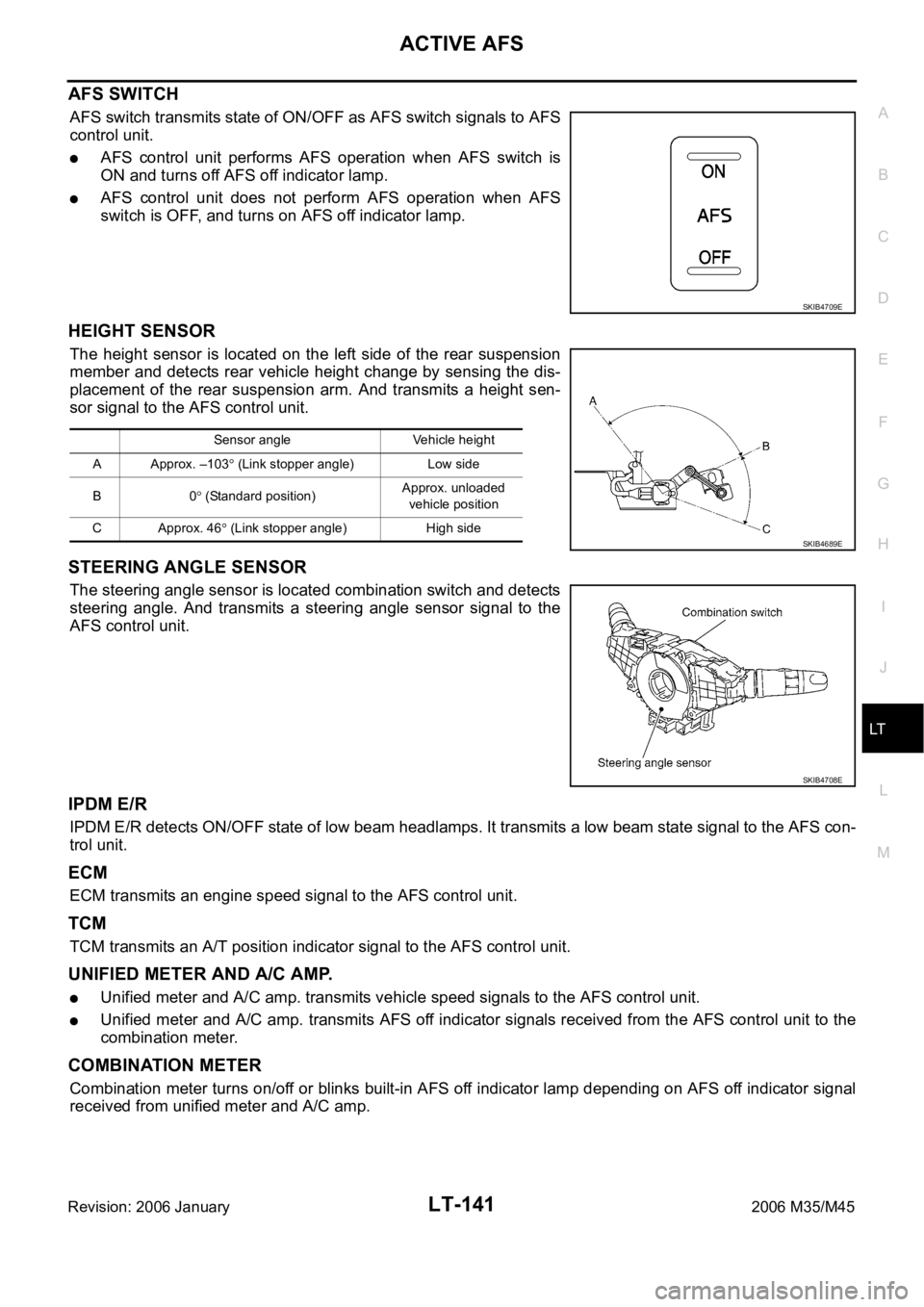
AFS SWITCH
AFS switch transmits state of ON/OFF as AFS switch signals to AFS
control unit.
AFS control unit performs AFS operation when AFS switch is
ON and turns off AFS off indicator lamp.
AFS control unit does not perform AFS operation when AFS
switch is OFF, and turns on AFS off indicator lamp.
HEIGHT SENSOR
The height sensor is located on the left side of the rear suspension
member and detects rear vehicle height change by sensing the dis-
placement of the rear suspension arm. And transmits a height sen-
sor signal to the AFS control unit.
STEERING ANGLE SENSOR
The steering angle sensor is located combination switch and detects
steering angle. And transmits a steering angle sensor signal to the
AFS control unit.
IPDM E/R
IPDM E/R detects ON/OFF state of low beam headlamps. It transmits a low beam state signal to the AFS con-
trol unit.
ECM
ECM transmits an engine speed signal to the AFS control unit.
TCM
TCM transmits an A/T position indicator signal to the AFS control unit.
UNIFIED METER AND A/C AMP.
Unified meter and A/C amp. transmits vehicle speed signals to the AFS control unit.
Unified meter and A/C amp. transmits AFS off indicator signals received from the AFS control unit to the
combination meter.
COMBINATION METER
Combination meter turns on/off or blinks built-in AFS off indicator lamp depending on AFS off indicator signal
received from unified meter and A/C amp.
SKIB4709E
Sensor angle Vehicle height
A Approx. –103
(Link stopper angle) Low side
B0
(Standard position)Approx. unloaded
vehicle position
C Approx. 46
(Link stopper angle) High side SKIB4689E
SKIB4708E
Page 4814 of 5621
CHASSIS AND BODY MAINTENANCE
MA-37
C
D
E
F
G
H
I
J
K
MA
B
MA
Revision: 2006 January2006 M35/M45
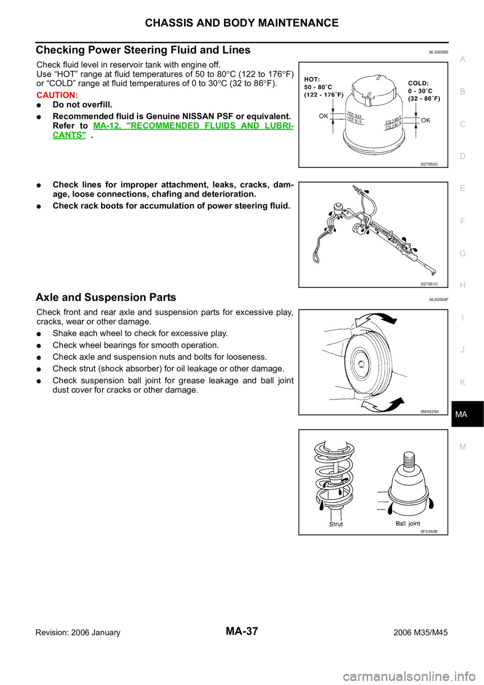
Checking Power Steering Fluid and LinesNLS0008E
Check fluid level in reservoir tank with engine off.
Use “HOT” range at fluid temperatures of 50 to 80
C (122 to 176F)
or “COLD” range at fluid temperatures of 0 to 30
C (32 to 86F).
CAUTION:
Do not overfill.
Recommended fluid is Genuine NISSAN PSF or equivalent.
Refer to MA-12, "
RECOMMENDED FLUIDS AND LUBRI-
CANTS" .
Check lines for improper attachment, leaks, cracks, dam-
age, loose connections, chafing and deterioration.
Check rack boots for accumulation of power steering fluid.
Axle and Suspension PartsNLS0008F
Check front and rear axle and suspension parts for excessive play,
cracks, wear or other damage.
Shake each wheel to check for excessive play.
Check wheel bearings for smooth operation.
Check axle and suspension nuts and bolts for looseness.
Check strut (shock absorber) for oil leakage or other damage.
Check suspension ball joint for grease leakage and ball joint
dust cover for cracks or other damage.
SST850C
SST851C
SMA525A
SFA392B