Page 5096 of 5621

FRONT LOWER LINK
RSU-15
C
D
F
G
H
I
J
K
L
MA
B
RSU
Revision: 2006 January2006 M35/M45
FRONT LOWER LINKPFP:55110
Removal and InstallationNES000JE
REMOVAL
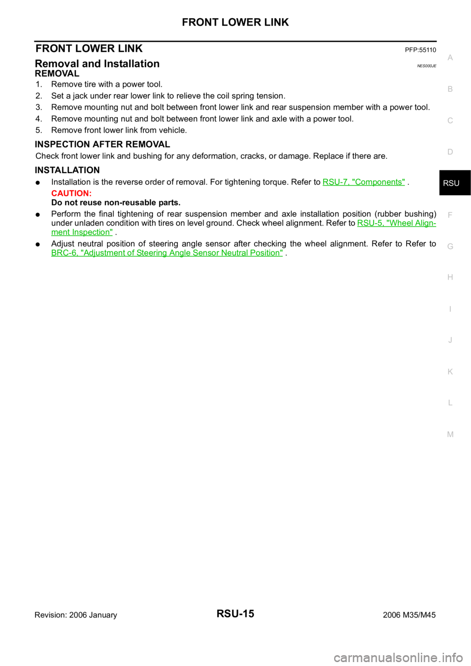
1. Remove tire with a power tool.
2. Set a jack under rear lower link to relieve the coil spring tension.
3. Remove mounting nut and bolt between front lower link and rear suspension member with a power tool.
4. Remove mounting nut and bolt between front lower link and axle with a power tool.
5. Remove front lower link from vehicle.
INSPECTION AFTER REMOVAL
Check front lower link and bushing for any deformation, cracks, or damage. Replace if there are.
INSTALLATION
Installation is the reverse order of removal. For tightening torque. Refer to RSU-7, "Components" .
CAUTION:
Do not reuse non-reusable parts.
Perform the final tightening of rear suspension member and axle installation position (rubber bushing)
under unladen condition with tires on level ground. Check wheel alignment. Refer to RSU-5, "
Wheel Align-
ment Inspection" .
Adjust neutral position of steering angle sensor after checking the wheel alignment. Refer to Refer to
BRC-6, "
Adjustment of Steering Angle Sensor Neutral Position" .
Page 5097 of 5621

RSU-16
REAR LOWER LINK & COIL SPRING
Revision: 2006 January2006 M35/M45
REAR LOWER LINK & COIL SPRINGPFP:551B0
Removal and InstallationNES000JF
REMOVAL
1. Remove tire with a power tool.
2. Set a jack under rear lower link to relieve the coil spring tension.
3. Loosen mounting bolt and nut of rear lower link inside of suspension member, and then remove mounting
bolt and nut inside of axle with a power tool.
4. Slowly lower jack, then remove upper seat, coil spring and rubber sheet from rear lower link.
5. Remove mounting bolt and nut inside of suspension member to remove rear lower link with a power tool.
INSPECTION AFTER REMOVAL
Check rear lower link, bushing and coil spring for deformation, cracks, and damage. Replace rear lower link
and coil spring if there are.
INSTALLATION
Installation is the reverse order of removal. For tightening torque. Refer to RSU-7, "Components" .
CAUTION:
Do not reuse non-reusable parts.
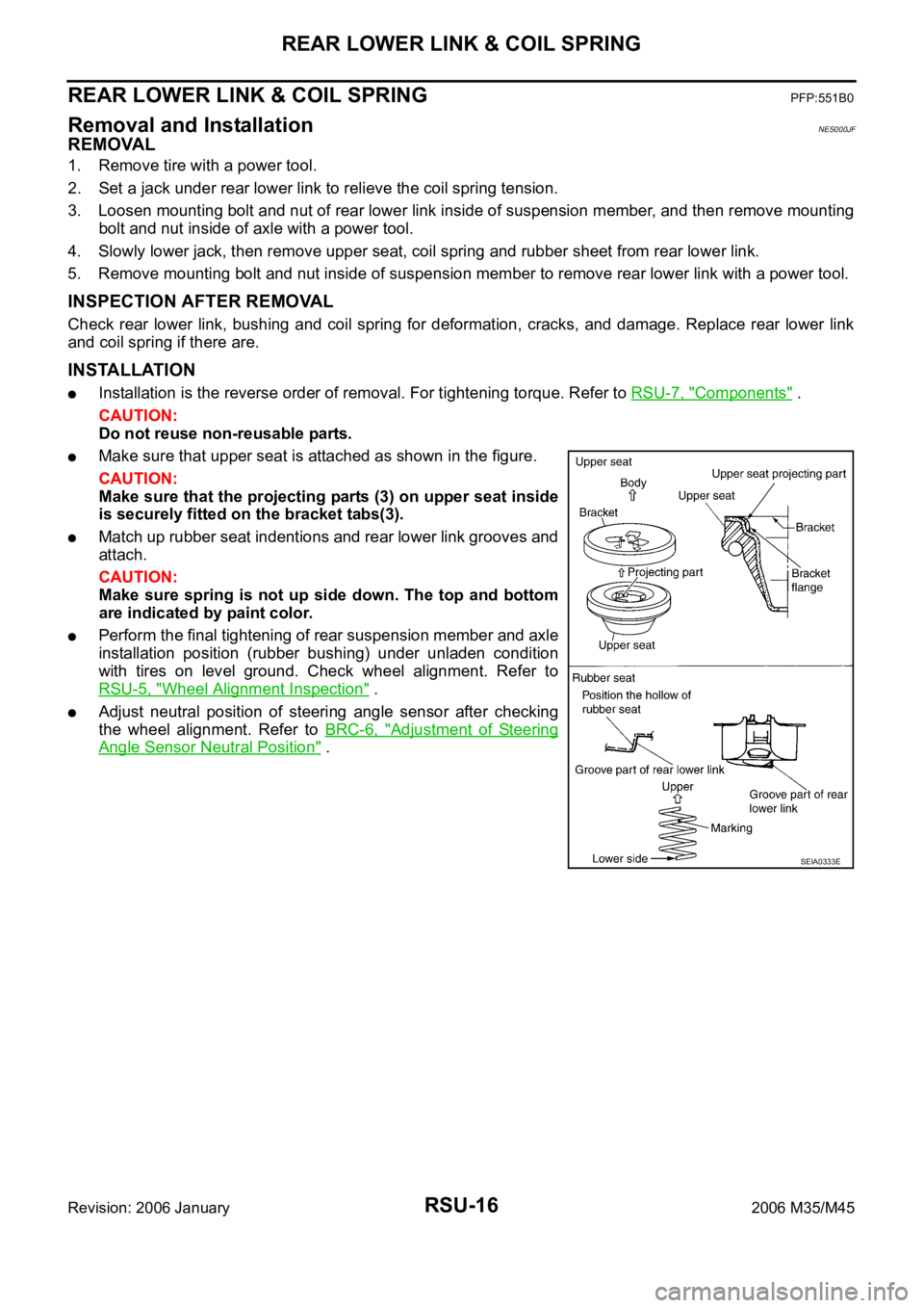
Make sure that upper seat is attached as shown in the figure.
CAUTION:
Make sure that the projecting parts (3) on upper seat inside
is securely fitted on the bracket tabs(3).
Match up rubber seat indentions and rear lower link grooves and
attach.
CAUTION:
Make sure spring is not up side down. The top and bottom
are indicated by paint color.
Perform the final tightening of rear suspension member and axle
installation position (rubber bushing) under unladen condition
with tires on level ground. Check wheel alignment. Refer to
RSU-5, "
Wheel Alignment Inspection" .
Adjust neutral position of steering angle sensor after checking
the wheel alignment. Refer to BRC-6, "
Adjustment of Steering
Angle Sensor Neutral Position" .
SEIA0333E
Page 5428 of 5621
![INFINITI M35 2006 Factory Service Manual REAR ACTIVE STEER
STC-13
[RAS]
C
D
E
F
H
I
J
K
L
MA
B
STC
Revision: 2006 January2006 M35/M45
[RAS]REAR ACTIVE STEERPFP:55705
Removal and InstallationNGS000E5
COMPONENTS
REMOVAL
1. Remove coil spring. INFINITI M35 2006 Factory Service Manual REAR ACTIVE STEER
STC-13
[RAS]
C
D
E
F
H
I
J
K
L
MA
B
STC
Revision: 2006 January2006 M35/M45
[RAS]REAR ACTIVE STEERPFP:55705
Removal and InstallationNGS000E5
COMPONENTS
REMOVAL
1. Remove coil spring.](/manual-img/42/57023/w960_57023-5427.png)
REAR ACTIVE STEER
STC-13
[RAS]
C
D
E
F
H
I
J
K
L
MA
B
STC
Revision: 2006 January2006 M35/M45
[RAS]REAR ACTIVE STEERPFP:55705
Removal and InstallationNGS000E5
COMPONENTS
REMOVAL
1. Remove coil spring. Refer to RSU-16, "REAR LOWER LINK & COIL SPRING" .
2. Disconnect harness connector from RAS actuator assembly and rear suspension member.
3. Remove fixing bolts and nuts of RAS actuator assembly (1), and
then remove RAS actuator assembly (1) from rear suspension
member.
INSTALLATION
Installation is the reverse order of removal. For tightening torque, refer to STC-13, "COMPONENTS" .
When installing RAS actuator assembly to rear suspension member, check the mounting surfaces of RAS
actuator assembly and rear suspension member for oil, dirt, sand, or other foreign materials.
To perform the neutral position adjustment. Refer to STC-14, "Neutral Position Adjustment" .
1. Rear lower link 2. Decenter cam 3. RAS actuator assembly
Refer to GI-11, "
Components" , for the symbols in the figure.
SGIA1238E
SGIA1239E
Page 5431 of 5621
![INFINITI M35 2006 Factory Service Manual STC-16
[RAS]
SYSTEM DESCRIPTION
Revision: 2006 January2006 M35/M45
SYSTEM DESCRIPTIONPFP:00000
ComponentsNGS000E8
RAS (Rear Active Steer) FunctionNGS000E9
A. RAS control unit B. Model following contro INFINITI M35 2006 Factory Service Manual STC-16
[RAS]
SYSTEM DESCRIPTION
Revision: 2006 January2006 M35/M45
SYSTEM DESCRIPTIONPFP:00000
ComponentsNGS000E8
RAS (Rear Active Steer) FunctionNGS000E9
A. RAS control unit B. Model following contro](/manual-img/42/57023/w960_57023-5430.png)
STC-16
[RAS]
SYSTEM DESCRIPTION
Revision: 2006 January2006 M35/M45
SYSTEM DESCRIPTIONPFP:00000
ComponentsNGS000E8
RAS (Rear Active Steer) FunctionNGS000E9
A. RAS control unit B. Model following control C. Target vehicle dynamics model
D. Rear wheel steering angle com-
mand value operationE. Rear wheel steering angle servo F. Vehicle speed signal (CAN)
G. Steering angle signal (CAN) H. Vehicle speed sensor I. Steering angle sensor
J. RAS actuator assembly
SGIA1241E
Part name Function
RAS control unit
Calculate the vehicle speed signal from CAN communication and the signals from steering
angle sensor and rear wheel steering angle sensor by a computer, and then control the rear
wheel steering angle.
Fail-safe function is activated when the electrical system is malfunctioning. The output signal
to the actuator is turned OFF during this mode. At that time, the RAS warning lamp illumi-
nates and indicates the system is malfunctioning.
It performs the communication control function with other control units via CAN communica-
tion.
This enables system diagnosis with CONSULT-II.
RAS actuatorThe efficiency of the rear wheel steer improves by locating the electric motor actuator into the
lower link of rear suspension.
Steering angle sensor
Measure the steering angle and send it to RAS control unit via CAN communication.
It is shared with the steering angle sensor for VDC.
Rear wheel steering angle sensor
It sends the rear wheel steering angle status to RAS control unit. The accuracy of rear wheel
steer improves by comparing the vehicle speed signal from CAN communication with the
rear wheel steering angle target value calculated from the wheel angle sensor signal, and it
controls them.
There are 2 types of rear wheel steering angle sensors (main/sub). If one of them is malfunc-
tioning, the other operates the fail-safe mode and stops the control.
RAS warning lamp
It turns on when the fail-safe function is operated and indicates that a RAS control malfunc-
tion has occurred.
It turns on when ignition switch turns on and turns off after the engine is started.
It indicates the suspect system by blinking when performing the self-diagnosis (without CON-
SULT-II).
Page 5463 of 5621
![INFINITI M35 2006 Factory Service Manual STC-48
[RAS]
TROUBLE DIAGNOSIS
Revision: 2006 January2006 M35/M45
Check RAS Static/Dynamic CharacteristicsNGS000F3
1. CHECK (1): RAS ACTUATOR STROKE
Perform CONSULT-II “ACTIVE TEST”, and then INFINITI M35 2006 Factory Service Manual STC-48
[RAS]
TROUBLE DIAGNOSIS
Revision: 2006 January2006 M35/M45
Check RAS Static/Dynamic CharacteristicsNGS000F3
1. CHECK (1): RAS ACTUATOR STROKE
Perform CONSULT-II “ACTIVE TEST”, and then](/manual-img/42/57023/w960_57023-5462.png)
STC-48
[RAS]
TROUBLE DIAGNOSIS
Revision: 2006 January2006 M35/M45
Check RAS Static/Dynamic CharacteristicsNGS000F3
1. CHECK (1): RAS ACTUATOR STROKE
Perform CONSULT-II “ACTIVE TEST”, and then check the actuator
stroke when turning the steering wheel clockwise or counterclock-
wise by 180
or more.
OK or NG
OK >> GO TO 2.
NG >> GO TO 3.
2. CHECK (2): RAS ACTUATOR STROKE
Perform CONSULT-II “ACTIVE TEST“. When turning the steering
wheel in neutral position (A), the rear wheel turns clockwise/counter-
clockwise periodically. At that time, check actuator stroke (B).
OK or NG
OK >> RAS static/dynamic characteristics inspection is com-
pleted.
NG >> GO TO 3.
3. CHECK RAS MOTOR
Check RAS motor itself separated from other parts. Refer to STC-49, "
RAS MOTOR" .
OK or NG
OK >> GO TO 4.
NG >> RAS motor malfunction. Check the stroke again after replacing.
4. CHECK REAR WHEEL STEERING ANGLE SENSOR
Check rear wheel steering angle sensor separated from other parts. Refer to STC-49, "
REAR WHEEL
STEERING ANGLE SENSOR" .
OK or NG
OK >> GO TO 5.
NG >> Rear wheel steering angle sensor malfunction. Check the stroke again after replacing.
5. CHECK RAS CONTROL UNIT
Replace RAS control unit. Check the symptom of malfunction again.
Is the malfunction corrected?
YES >> RAS control unit malfunction
NO >> GO TO 6.
6. REPLACE RAS ACTUATOR ASSEMBLY
Replace RAS actuator assembly. Check the symptom of malfunction again.
Is the malfunction corrected?
YES >> RAS actuator malfunction
NO >> Check rear suspension components. Refer to RSU-7, "
Components" . Neutral position (A)
Actuator stroke (B) : 2.8 - 3.0 mm (0.110 - 0.118 in)
SGIA1240E
Actuator stroke (B) : 2.3 - 2.5 mm (0.091 - 0.098 in)
SGIA1240E
Page 5530 of 5621

NOISE, VIBRATION AND HARSHNESS (NVH) TROUBLESHOOTING
WT-5
C
D
F
G
H
I
J
K
L
MA
B
WT
Revision: 2006 January2006 M35/M45
NOISE, VIBRATION AND HARSHNESS (NVH) TROUBLESHOOTINGPFP:00003
NVH Troubleshooting ChartNES000JN
Use chart below to help you find the cause of the symptom. If necessary, repair or replace these parts.
: ApplicableReference page
FAX-5
, FSU-6WT-6WT-7WT-41WT-8—
—
WT-41
NVH in PR section.
NVH in RFD section.
NVH in FAX and FSU sections.
NVH in RAX and RSU sections.
Refer to TIRES in this chart.
Refer to ROAD WHEEL in this chart.
NVH in FAX, RAX section.
NVH in BR section.
NVH in PS section.
Possible cause and SUSPECTED PARTS
Improper installation, looseness
Out-of-round
Imbalance
Incorrect tire pressure
Uneven tire wear
Deformation or damage
Non-uniformity
Incorrect tire size
PROPELLER SHAFT
DIFFERENTIAL
FRONT AXLE AND FRONT SUSPENSION
REAR AXLE AND REAR SUSPENSION
TIRES
ROAD WHEELS
DRIVE SHAFT
BRAKE
STEERING
SymptomTIRESNoise
Shake
Vibration
Shimmy
Judder
Poor quality ride or
handling
ROAD
WHEELNoiseShake
Shimmy, Judder
Poor quality ride or
handling