2006 INFINITI M35 check engine
[x] Cancel search: check enginePage 1124 of 5621
INTELLIGENT KEY SYSTEM/ENGINE START FUNCTION
BL-185
C
D
E
F
G
H
J
K
L
MA
B
BL
Revision: 2006 January2006 M35/M45
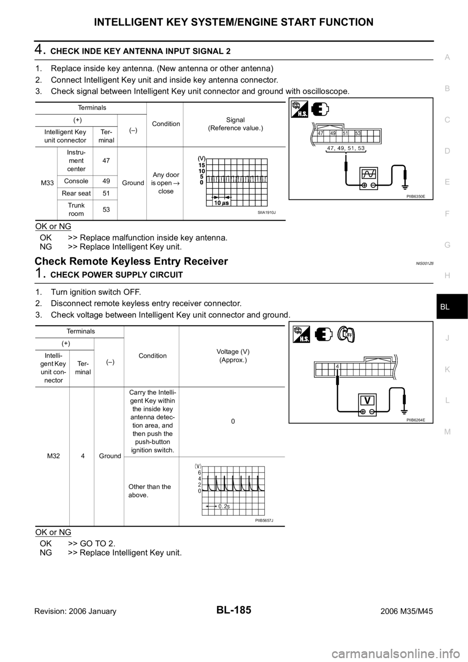
4. CHECK INDE KEY ANTENNA INPUT SIGNAL 2
1. Replace inside key antenna. (New antenna or other antenna)
2. Connect Intelligent Key unit and inside key antenna connector.
3. Check signal between Intelligent Key unit connector and ground with oscilloscope.
OK or NG
OK >> Replace malfunction inside key antenna.
NG >> Replace Intelligent Key unit.
Check Remote Keyless Entry ReceiverNIS001Z6
1. CHECK POWER SUPPLY CIRCUIT
1. Turn ignition switch OFF.
2. Disconnect remote keyless entry receiver connector.
3. Check voltage between Intelligent Key unit connector and ground.
OK or NG
OK >> GO TO 2.
NG >> Replace Intelligent Key unit.
Terminals
ConditionSignal
(Reference value.) (+)
(–)
Intelligent Key
unit connectorTe r -
minal
M33Instru-
ment
center47
GroundAny door
is open
close Console 49
Rear seat 51
Trunk
room53
PIIB6350E
SIIA1910J
Terminals
ConditionVoltage (V)
(Approx.) (+)
(–) Intelli-
gent Key
unit con-
nectorTe r -
minal
M32 4 GroundCarry the Intelli-
gent Key within
the inside key
antenna detec-
tion area, and
then push the
push-button
ignition switch.0
Other than the
above.
PIIB6264E
PIIB5657J
Page 1125 of 5621
BL-186
INTELLIGENT KEY SYSTEM/ENGINE START FUNCTION
Revision: 2006 January2006 M35/M45
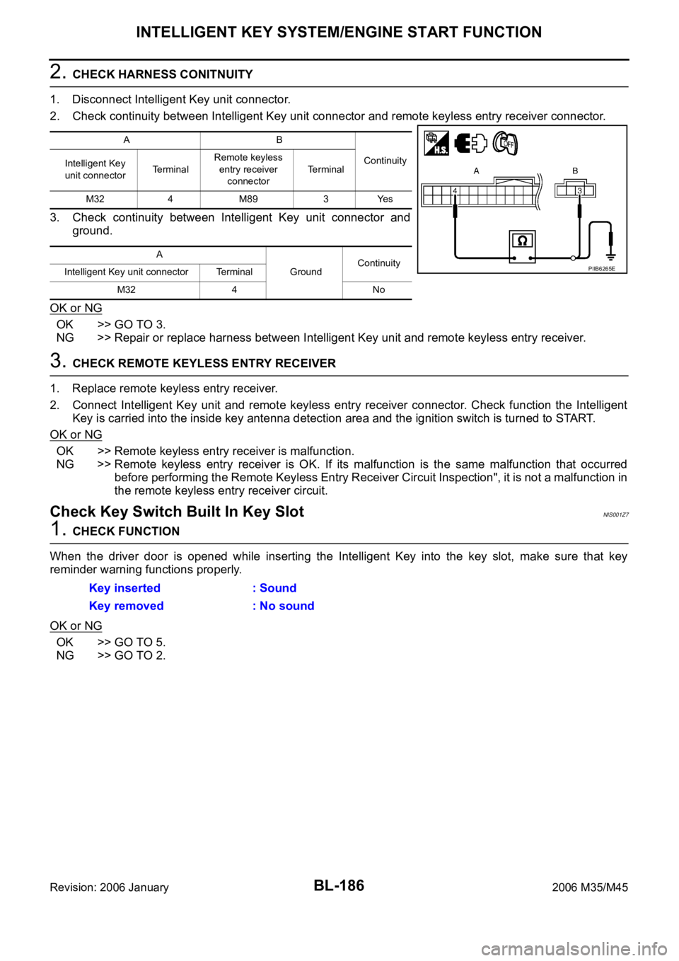
2. CHECK HARNESS CONITNUITY
1. Disconnect Intelligent Key unit connector.
2. Check continuity between Intelligent Key unit connector and remote keyless entry receiver connector.
3. Check continuity between Intelligent Key unit connector and
ground.
OK or NG
OK >> GO TO 3.
NG >> Repair or replace harness between Intelligent Key unit and remote keyless entry receiver.
3. CHECK REMOTE KEYLESS ENTRY RECEIVER
1. Replace remote keyless entry receiver.
2. Connect Intelligent Key unit and remote keyless entry receiver connector. Check function the Intelligent
Key is carried into the inside key antenna detection area and the ignition switch is turned to START.
OK or NG
OK >> Remote keyless entry receiver is malfunction.
NG >> Remote keyless entry receiver is OK. If its malfunction is the same malfunction that occurred
before performing the Remote Keyless Entry Receiver Circuit Inspection", it is not a malfunction in
the remote keyless entry receiver circuit.
Check Key Switch Built In Key SlotNIS001Z7
1. CHECK FUNCTION
When the driver door is opened while inserting the Intelligent Key into the key slot, make sure that key
reminder warning functions properly.
OK or NG
OK >> GO TO 5.
NG >> GO TO 2.
AB
Continuity
Intelligent Key
unit connectorTe r m i n a lRemote keyless
entry receiver
connectorTerminal
M32 4 M89 3 Yes
A
GroundContinuity
Intelligent Key unit connector Terminal
M32 4 No
PIIB6265E
Key inserted : Sound
Key removed : No sound
Page 1126 of 5621
INTELLIGENT KEY SYSTEM/ENGINE START FUNCTION
BL-187
C
D
E
F
G
H
J
K
L
MA
B
BL
Revision: 2006 January2006 M35/M45
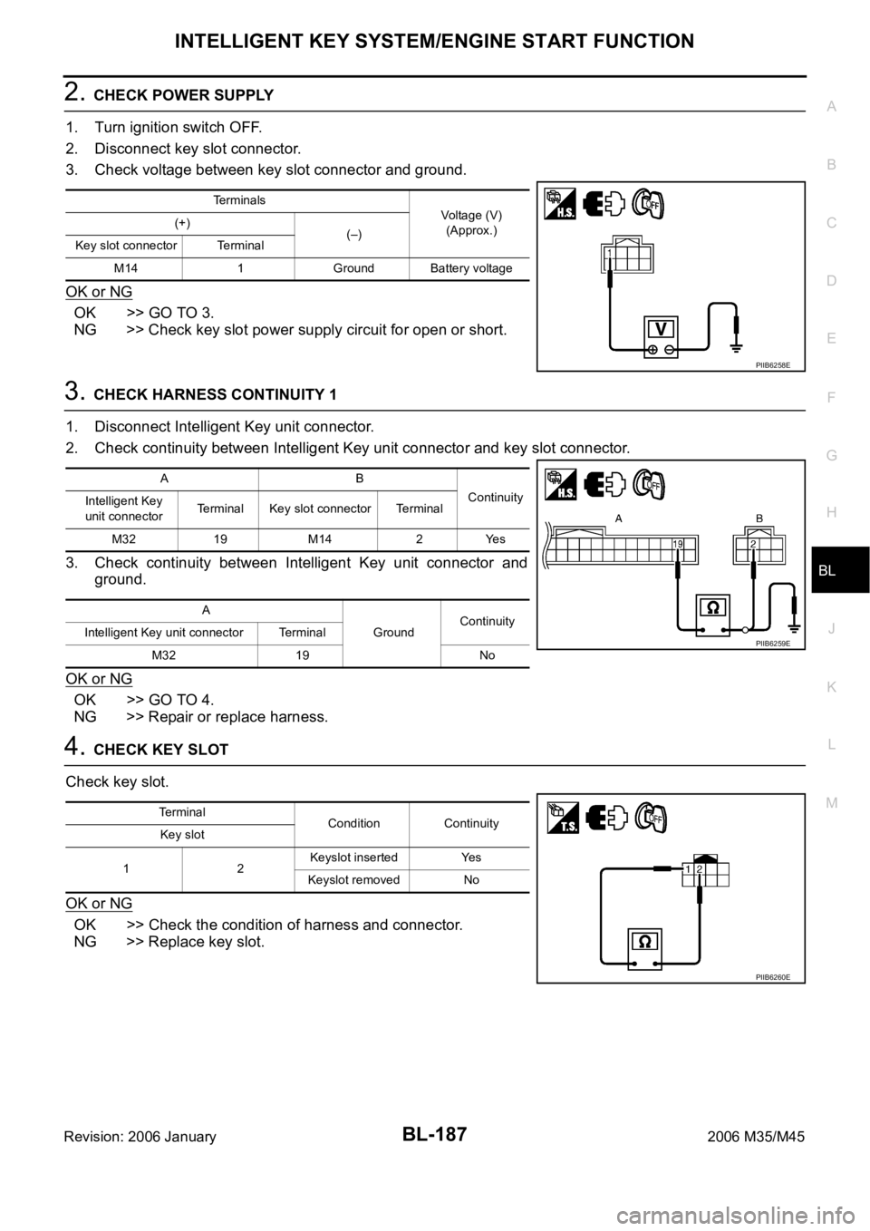
2. CHECK POWER SUPPLY
1. Turn ignition switch OFF.
2. Disconnect key slot connector.
3. Check voltage between key slot connector and ground.
OK or NG
OK >> GO TO 3.
NG >> Check key slot power supply circuit for open or short.
3. CHECK HARNESS CONTINUITY 1
1. Disconnect Intelligent Key unit connector.
2. Check continuity between Intelligent Key unit connector and key slot connector.
3. Check continuity between Intelligent Key unit connector and
ground.
OK or NG
OK >> GO TO 4.
NG >> Repair or replace harness.
4. CHECK KEY SLOT
Check key slot.
OK or NG
OK >> Check the condition of harness and connector.
NG >> Replace key slot.
Terminals
Voltage (V)
(Approx.) (+)
(–)
Key slot connector Terminal
M14 1 Ground Battery voltage
PIIB6258E
AB
Continuity
Intelligent Key
unit connectorTerminal Key slot connector Terminal
M32 19 M14 2 Yes
A
GroundContinuity
Intelligent Key unit connector Terminal
M32 19 No
PIIB6259E
Terminal
Condition Continuity
Key slot
12Keyslot inserted Yes
Keyslot removed No
PIIB6260E
Page 1127 of 5621
BL-188
INTELLIGENT KEY SYSTEM/ENGINE START FUNCTION
Revision: 2006 January2006 M35/M45
5. CHECK HARNESS CONTINUITY 2
1. Disconnect BCM connector.
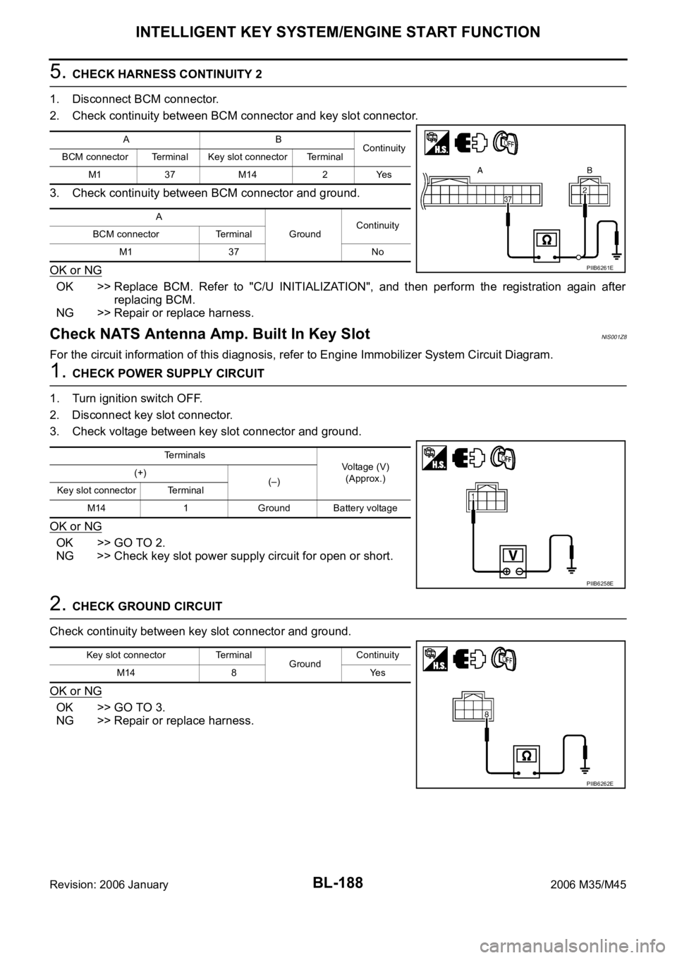
2. Check continuity between BCM connector and key slot connector.
3. Check continuity between BCM connector and ground.
OK or NG
OK >> Replace BCM. Refer to "C/U INITIALIZATION", and then perform the registration again after
replacing BCM.
NG >> Repair or replace harness.
Check NATS Antenna Amp. Built In Key SlotNIS001Z8
For the circuit information of this diagnosis, refer to Engine Immobilizer System Circuit Diagram.
1. CHECK POWER SUPPLY CIRCUIT
1. Turn ignition switch OFF.
2. Disconnect key slot connector.
3. Check voltage between key slot connector and ground.
OK or NG
OK >> GO TO 2.
NG >> Check key slot power supply circuit for open or short.
2. CHECK GROUND CIRCUIT
Check continuity between key slot connector and ground.
OK or NG
OK >> GO TO 3.
NG >> Repair or replace harness.
AB
Continuity
BCM connector Terminal Key slot connector Terminal
M1 37 M14 2 Yes
A
GroundContinuity
BCM connector Terminal
M1 37 No
PIIB6261E
Terminals
Voltage (V)
(Approx.) (+)
(–)
Key slot connector Terminal
M14 1 Ground Battery voltage
PIIB6258E
Key slot connector Terminal
GroundContinuity
M14 8 Yes
PIIB6262E
Page 1128 of 5621
INTELLIGENT KEY SYSTEM/ENGINE START FUNCTION
BL-189
C
D
E
F
G
H
J
K
L
MA
B
BL
Revision: 2006 January2006 M35/M45
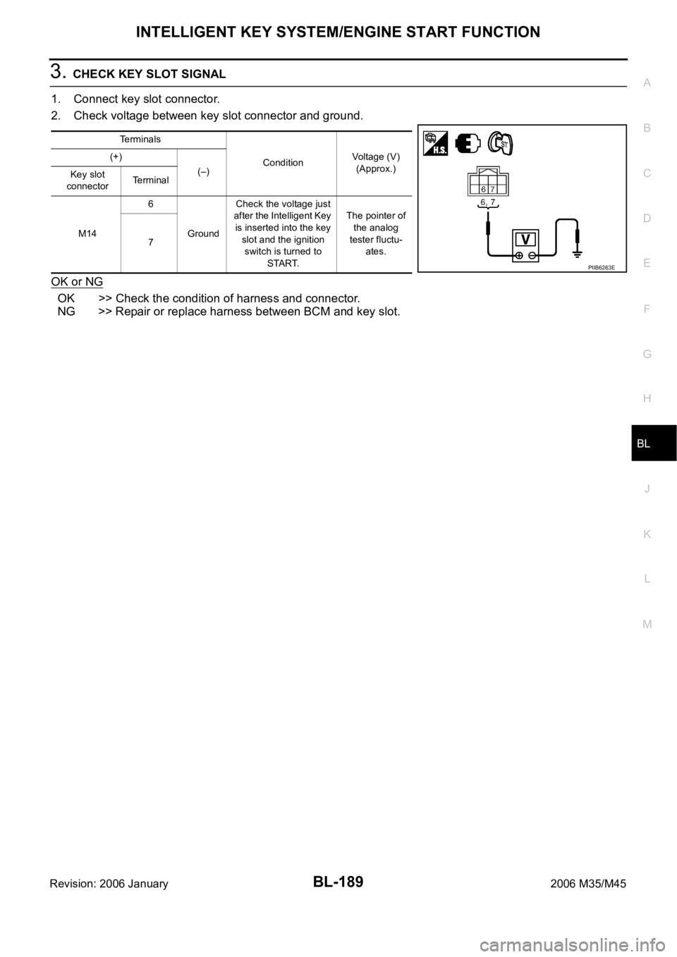
3. CHECK KEY SLOT SIGNAL
1. Connect key slot connector.
2. Check voltage between key slot connector and ground.
OK or NG
OK >> Check the condition of harness and connector.
NG >> Repair or replace harness between BCM and key slot.
Terminals
ConditionVoltage (V)
(Approx.) (+)
(–)
Key slot
connectorTerminal
M146
GroundCheck the voltage just
after the Intelligent Key
is inserted into the key
slot and the ignition
switch is turned to
START.The pointer of
the analog
tester fluctu-
ates. 7
PIIB6263E
Page 1210 of 5621

IVIS (INFINITI VEHICLE IMMOBILIZER SYSTEM-NATS)
BL-271
C
D
E
F
G
H
J
K
L
MA
B
BL
Revision: 2006 January2006 M35/M45
“NATS V5.0” SELF-DIAGNOSTIC RESULTS ITEM CHART
“NATS BCM OR S/ENT” SELF-DIAGNOSTIC RESULTS ITEM CHART
Suspect Systems Description Possible malfunction Action to take/Reference page
NO DTC NO DTC — —
DON'T ERASE BEFORE
CHECKING ENG DIAGThere is the engine trouble
diagnosis information in ECM
(ECM trouble diagnosis is nec-
essary separately)Engine control system malfunc-
tionThere is the engine trouble
diagnosis information in ECM.
Check the trouble diagnostic
results of “ENGINE” before
that.
LOCK MODE
[P1610]The immobilizer switches to the
mode that prevents the engine
from being started. If the ID ver-
ification between BCM and
ECM is NG, the ID verification
malfunction between remote
control starter and BCM may be
detected 5 times or more.—When “LOCK MODE” is dis-
played, check for any other dis-
played malfunction, and then
erase the self-diagnostic results
after replacement.
ID DISCORD, IMM-ECM
[P1611]The ID verification results
between BCM and ECM are
NG. The registration is neces-
sary.Registration of ECM is not com-
pletedBL-280
ECM malfunction Replace ECM.
CHAIN OF ECM-IMMU
[P1612]Inactive communication
between ECM and BCMOpen circuit in battery power
supply line of BCM
BL-278
Open circuit in ignition power
supply line of BCM
Open circuit in ground of BCM
Short circuit in communication
line between BCM and ECM to
power supply line
Open circuit in communication
line between BCM and ECM
Short circuit in communication
line between BCM and ECM to
ground
ECM malfunction
BCM malfunction
CHAIN OF IMMU-KEY
[P1614]BCM malfunction BCM malfunctionBCS-17
Suspect Systems Description Possible malfunction Action to take/Reference page
NO DTC NO DTC — —
ID DISCORD BCM-ECM
[B2192]The ID verification results
between BCM and ECM are
NG. The registration is neces-
sary.Registration of ECM is not com-
pletedPerform “Control Unit Initializa-
tion”, and then perform the ID
registration. Refer to the Tech-
nical Bulletin.
ECM malfunction Replace ECM.
CHAIN OF BCM-ECM
[B2193]Inactive communication
between ECM and BCMShort circuit in communication
line between BCM and ECM to
power supply lineMalfunction have occurred in
CAN communication
Check “Self-diagnostic Results”
of “Intelligent Key” using CON-
SULT-II. Refer to BL-152,
"SELF-DIAGNOSTIC
RESULTS" . Open circuit in communication
line between BCM and ECM
Short circuit in communication
line between BCM and ECM to
ground
ECM malfunction Replace ECM.
Page 1211 of 5621
BL-272
IVIS (INFINITI VEHICLE IMMOBILIZER SYSTEM-NATS)
Revision: 2006 January2006 M35/M45
“NATS I-KEY” SELF-DIAGNOSTIC RESULTS ITEM CHART
Work FlowNIS0020O
1. LISTEN TO CUSTOMER COMPLAINT OR REQUEST
Get symptoms or listen to customer complaints or request.
NOTE:
In case of request for Intelligent Key or IVIS (NATS) system repair, the key ID re-registration might be neces-
sary. Keep all the Intelligent Keys before work for the re-registration.
Key ID registration request>>Register Intelligent Key by referring to CONSULT-II operation manual IVIS/
NVIS NATS.
Request for malfunction repair.>>GO TO 2.
2. CHECK DOOR LOCK AND REMOTE CONTROL FUNCTION
Check that Door Lock and remote control function of Intelligent Key operate normally.
Door Lock or remote control function is malfunctioning.>>Malfunction of Door Lock and remote control func-
tion, Refer to
Door Lock and remote control function are normal.>>GO TO 3.
DISCORD BCM-I-KEY
[B2194]The ID verification results
between BCM and Intelligent
Key unit are NG.Short circuit in communication
line between BCM and Intelli-
gent Key unit to power supply
lineMalfunction have occurred in
CAN communication
Check “Self-diagnostic Results”
of “Intelligent Key” using CON-
SULT-II. Refer to BL-152,
"SELF-DIAGNOSTIC
RESULTS" . Short circuit in communication
line between BCM and ECM to
ground
Intelligent Key unit malfunctionBL-125
ANTI-SCANNING
[B2195]A remote control starter that is
not Genuine NISSAN is
installedIf a remote control starter that is
not Genuine NISSAN is
installed, the anti-theft system
is activated and the engine may
not be started. In this case,
remove the parts after the cus-
tomer understands the situa-
tion.— Suspect Systems Description Possible malfunction Action to take/Reference page
Suspect Systems Description Possible malfunction Action to take/Reference page
NO DTC NO DTC — —
DISCORD BCM-I-KEY
[B2590]The ID verification results
between Intelligent Key unit
and BCM are NG.Short circuit in communication
line between BCM and Intelli-
gent Key unit to power supply
lineMalfunction have occurred in
CAN communication
Check “Self-diagnostic Results”
of “Intelligent Key” using CON-
SULT-II. Refer to BL-152,
"SELF-DIAGNOSTIC
RESULTS" . Short circuit in communication
line between BCM and ECM to
ground
BCM malfunctionBCS-17
Page 1213 of 5621
BL-274
IVIS (INFINITI VEHICLE IMMOBILIZER SYSTEM-NATS)
Revision: 2006 January2006 M35/M45
8. CHECK TURNING TIMING OF POWER SOURCE POSITION 2
Check all the Intelligent Keys for power source turning delay time after Push-button ignition switch is pushed
with Intelligent Key inserted into key slot. (Approx. 3 sec)
CAUTION:
Operate Push-button ignition switch without depressing the brake pedal.
No delay time exists>>GO TO 9.
Delay time exists when operated with particular Intelligent Key.>>Perform “C/U INITIALIZATION” referring to
CONSULT-II operation manual IVIS/NVIS NATS. In case that delay time still exists after the initial-
ization, replace the Intelligent Key.
Delay time exists when operated with any of the Intelligent Keys.>>Perform Trouble diagnosis symptom
chart 3. Refer to BL-180, "
Trouble Diagnosis Symptom Chart 3" .
9. CHECK ENGINE START FUNCTION
Check that engine can be started with Intelligent Key carried and inserted into the key slot respectively.
Engine can be started.>>GO TO 10.
Engine cannot be started.>>Inspect Trouble Diagnosis Flow Chart for IVIS (NATS). Refer to BL-275, "
Trou-
ble Diagnoses Flow Chart for IVIS (NATS)" .
10. CHECK SECURITY INDICATOR FUNCTION
Check Security Indicator for lighting up under the two conditions below.
Security Indicator lights off when Push-button ignition switch is pushed with Intelligent Key inserted into or
pulled out of the key slot.
Security Indicator blinks when Intelligent Key is pulled out and Push-button ignition switch is in lock posi-
tion.
Lighting up condition is normal.>>Inspection END.
Lighting up condition is malfunctioning.>>Perform Security Indicator Inspection. Refer to BL-277, "
Symptom
Chart for Security Indicator" .