2006 INFINITI M35 sensor
[x] Cancel search: sensorPage 5485 of 5621

TF-20
TROUBLE DIAGNOSIS
Revision: 2006 January2006 M35/M45
Trouble Diagnosis Chart for SymptomsNDS000DK
If AWD warning lamp turns ON, perform self-diagnosis. Refer to TF-22, "SELF-DIAG RESULT MODE" .
NOTE:
Light tight-corner braking symptom may occur depending on driving conditions. This is not malfunction.
AWD Control Unit Input/Output Signal Reference ValuesNDS000DL
AWD CONTROL UNIT INSPECTION TABLE
Specifications with CONSULT-II
Symptom Condition Check item Reference page
AWD warning lamp does not turn ON when
the ignition switch is turned to ON.
(AWD warning lamp check)Ignition switch: ONCAN communication line
TF-33
Unified meter and A/C amp.
Unified meter control unit
AWD warning lamp does not turn OFF sev-
eral seconds after engine started.Engine runningCAN communication line
TF-33
Power supply and ground for AWD con-
trol unit
Unified meter and A/C amp.
Unified meter control unit
AWD solenoid
AWD actuator relay (integrated in AWD
control unit)
Wheel sensor
Heavy tight-corner braking symptom occurs
when the vehicle is driven and the steering
wheel is turned fully to either side after the
engine is started. (See NOTE.)
While driving
Steering wheel is
turned fully to either
sidesCAN communication line
TF-35Accelerator pedal position signal
AWD solenoid
Mechanical malfunction of electric con-
trolled coupling (clutch sticking etc.)
Vehicle does not enter AWD mode even
though AWD warning lamp turned to OFF.While drivingCAN communication line
TF-36
AWD solenoid
Mechanical malfunction of electric con-
trolled coupling (Mechanical engage-
ment of clutch is not possible.)
While driving, AWD warning lamp flashes
rapidly. (When flashing in approx. 1 minute
and then turning OFF.)
Rapid flashing: 2 times/secondWhile drivingProtection function is activated due to
heavy load to electric controlled cou-
pling. (AWD system is not malfunction-
ing. Also, optional distribution of torque
sometimes becomes rigid before lamp
flashes rapidly, but it is not malfunction.)TF-37
While driving, AWD warning lamp flashes
slowly. (When continuing to flash until turn-
ing ignition switch OFF)
Slow flashing: 1 time/2 secondsWhile driving
Vehicle speed: 20 km/h
(12 MPH) or moreTire size is different between front and
rear of vehicle.TF-37
Monitor item [Unit] Content Condition Display value
FR RH SENSOR [km/h] or [mph]Wheel speed (Front wheel
right)Vehicle stopped 0.00 km/h (0.00 mph)
Vehicle running
CAUTION:
Check air pressure of tire under
standard condition.Approximately equal to
the indication on speed-
ometer (Inside of
10%)
FR LH SENSOR [km/h] or [mph]Wheel speed (Front wheel
left)Vehicle stopped 0.00 km/h (0.00 mph)
Vehicle running
CAUTION:
Check air pressure of tire under
standard condition.Approximately equal to
the indication on speed-
ometer (Inside of
10%)
Page 5486 of 5621

TROUBLE DIAGNOSIS
TF-21
C
E
F
G
H
I
J
K
L
MA
B
TF
Revision: 2006 January2006 M35/M45
*1 : The values are changed by throttle opening and engine speed.
*2 : Mode switch is not equipped, but displayed.
CONSULT-II Function (ALL MODE AWD/4WD)NDS000DM
FUNCTION
CONSULT-II can display each diagnostic item using the diagnostic test modes shown following.
RR RH SENSOR [km/h] or [mph]Wheel speed (Rear wheel
right)Vehicle stopped 0.00 km/h (0.00 mph)
Vehicle running
CAUTION:
Check air pressure of tire under
standard condition.Approximately equal to
the indication on speed-
ometer (Inside of
10%)
RR LH SENSOR [km/h] or [mph]Wheel speed (Rear wheel
left)Vehicle stopped 0.00 km/h (0.00 mph)
Vehicle running
CAUTION:
Check air pressure of tire under
standard condition.Approximately equal to
the indication on speed-
ometer (Inside of
10%)
BATTERY VOLT [V]Power supply voltage for
AWD control unitIgnition switch: ON Battery voltage
THRTL POS SEN [%] Throttle opening conditionWhen depressing accelerator pedal
(Value rises gradually in response to
throttle position.)0 - 100%
ETS SOLENOID [A]Monitored value of current at
AWD solenoidEngine running
At idle speedApprox. 0.000A
Engine running
When depressing accelerator
pedalApprox. 0.000 - 0.500A*1
STOP LAMP SW [ON/OFF]Condition of brake pedal
operationBrake pedal: Depressed ON
Brake pedal: Released OFF
ENG SPEED SIG [RUN/STOP] Condition of engine runningEngine stopped
(Engine speed: Less than 400 rpm)STOP
Engine running
(Engine speed: 400 rpm or more)RUN
ETS ACTUATOR [ON/OFF]Operating condition of AWD
actuator relay (integrated in
AWD control unit)Engine stopped (Ignition
switch: ON)OFF
Engine running ON
4WD WARN LAMP [ON/OFF] AWD warning lamp conditionAWD warning lamp: ON ON
AWD warning lamp: OFF OFF
4WD MODE SW*
2 [AUTO]Input condition from mode
switchAlways AUTO
4WD MODE MON [AUTO] Control status of AWD Engine running AUTO
DIS-TIRE MONI [mm]Improper size tire installed
conditionVehicle running with normal size tire
installed0-4 mm
Vehicle running with improper size
tire installed (Front/rear tire size dif-
ference, wear condition)4-8 mm, 8- mm
P BRAKE SW [ON/OFF] Condition of parking brakeParking brake operated ON
Parking brake not operated OFF Monitor item [Unit] Content Condition Display value
Diagnostic test mode FunctionReference
page
Self-diagnostic results
Self-diagnostic results can be read and erased quickly.TF-22
Data monitorInput/Output data in the AWD control unit can be read.TF-24
Page 5487 of 5621

TF-22
TROUBLE DIAGNOSIS
Revision: 2006 January2006 M35/M45
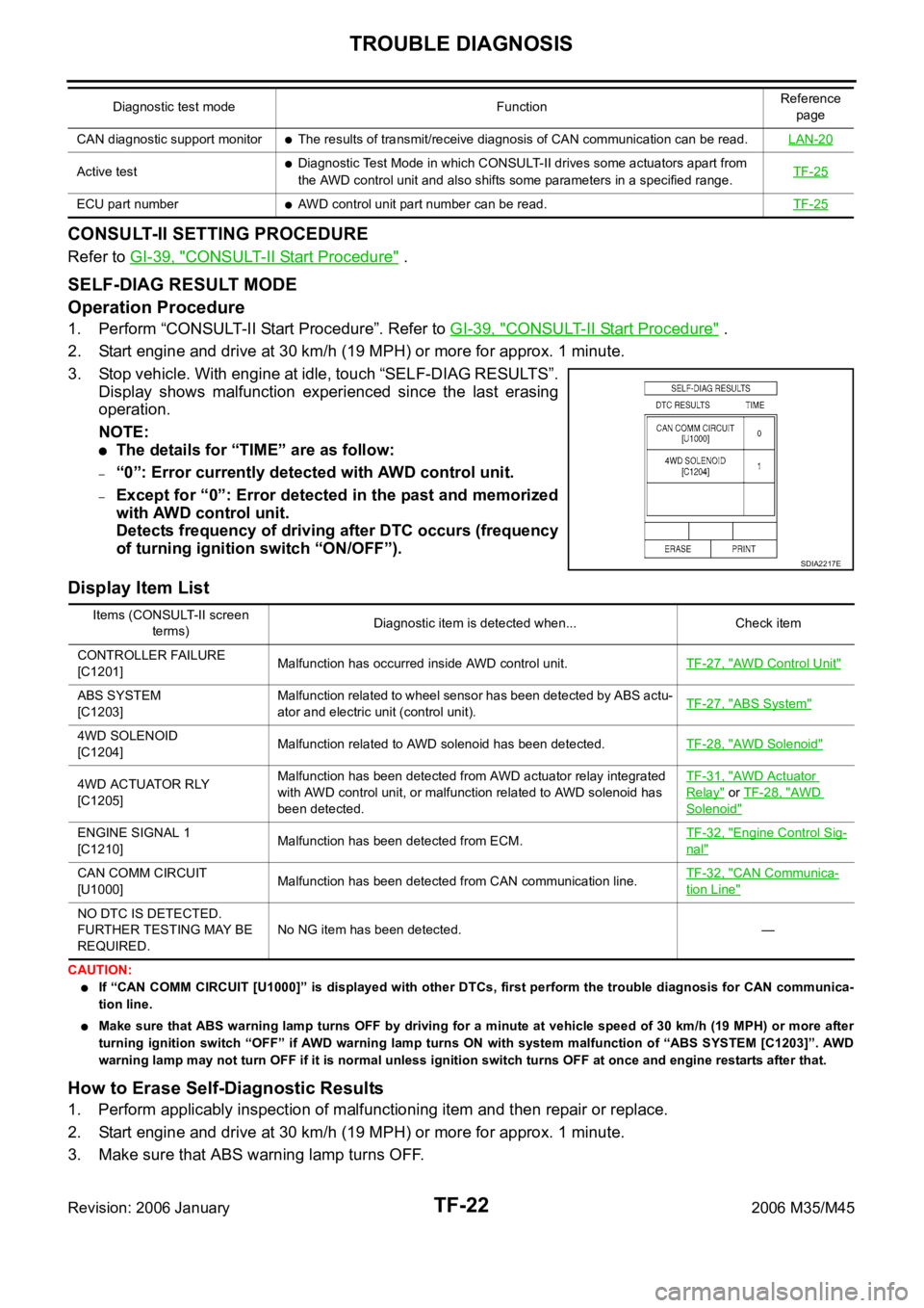
CONSULT-II SETTING PROCEDURE
Refer to GI-39, "CONSULT-II Start Procedure" .
SELF-DIAG RESULT MODE
Operation Procedure
1. Perform “CONSULT-II Start Procedure”. Refer to GI-39, "CONSULT-II Start Procedure" .
2. Start engine and drive at 30 km/h (19 MPH) or more for approx. 1 minute.
3. Stop vehicle. With engine at idle, touch “SELF-DIAG RESULTS”.
Display shows malfunction experienced since the last erasing
operation.
NOTE:
The details for “TIME” are as follow:
–“0”: Error currently detected with AWD control unit.
–Except for “0”: Error detected in the past and memorized
with AWD control unit.
Detects frequency of driving after DTC occurs (frequency
of turning ignition switch “ON/OFF”).
Display Item List
CAUTION:
If “CAN COMM CIRCUIT [U1000]” is displayed with other DTCs, first perform the trouble diagnosis for CAN communica-
tion line.
Make sure that ABS warning lamp turns OFF by driving for a minute at vehicle speed of 30 km/h (19 MPH) or more after
turning ignition switch “OFF” if AWD warning lamp turns ON with system malfunction of “ABS SYSTEM [C1203]”. AWD
warning lamp may not turn OFF if it is normal unless ignition switch turns OFF at once and engine restarts after that.
How to Erase Self-Diagnostic Results
1. Perform applicably inspection of malfunctioning item and then repair or replace.
2. Start engine and drive at 30 km/h (19 MPH) or more for approx. 1 minute.
3. Make sure that ABS warning lamp turns OFF.
CAN diagnostic support monitorThe results of transmit/receive diagnosis of CAN communication can be read.LAN-20
Active testDiagnostic Test Mode in which CONSULT-II drives some actuators apart from
the AWD control unit and also shifts some parameters in a specified range.TF-25
ECU part numberAWD control unit part number can be read.TF-25
Diagnostic test mode FunctionReference
page
SDIA2217E
Items (CONSULT-II screen
terms)Diagnostic item is detected when... Check item
CONTROLLER FAILURE
[C1201]Malfunction has occurred inside AWD control unit.TF-27, "
AWD Control Unit"
ABS SYSTEM
[C1203]Malfunction related to wheel sensor has been detected by ABS actu-
ator and electric unit (control unit).TF-27, "ABS System"
4WD SOLENOID
[C1204]Malfunction related to AWD solenoid has been detected.TF-28, "AWD Solenoid"
4WD ACTUATOR RLY
[C1205]Malfunction has been detected from AWD actuator relay integrated
with AWD control unit, or malfunction related to AWD solenoid has
been detected.TF-31, "AWD Actuator
Relay" or TF-28, "AWD
Solenoid"
ENGINE SIGNAL 1
[C1210]Malfunction has been detected from ECM.TF-32, "Engine Control Sig-
nal"
CAN COMM CIRCUIT
[U1000]Malfunction has been detected from CAN communication line.TF-32, "CAN Communica-
tion Line"
NO DTC IS DETECTED.
FURTHER TESTING MAY BE
REQUIRED.No NG item has been detected. —
Page 5489 of 5621

TF-24
TROUBLE DIAGNOSIS
Revision: 2006 January2006 M35/M45
DATA MONITOR MODE
Operation Procedure
1. Perform “CONSULT-II Start Procedure”. Refer to GI-39, "CONSULT-II Start Procedure" .
2. Touch “DATA MONITOR”.
3. Select from “SELECT MONITOR ITEM”, screen of data monitor mode is displayed.
NOTE:
When malfunction is detected, CONSULT-II performs REAL-TIME DIAGNOSIS.
Also, any malfunction detected while in this mode will be displayed at real time.
Display Item List
: Standard –: Not applicable
Monitor item (Unit)SELECT MONITOR ITEM
Remarks
ECU INPUT
SIGNALSMAIN
SIGNALSSELECTION
FROM MENU
FR RH SENSOR [km/h] or [mph]
Wheel speed calculated by front wheel
sensor RH signal is displayed.
FR LH SENSOR [km/h] or [mph]
Wheel speed calculated by front wheel
sensor LH signal is displayed.
RR RH SENSOR [km/h] or [mph]
Wheel speed calculated by rear wheel
sensor RH signal is displayed.
RR LH SENSOR [km/h] or [mph]
Wheel speed calculated by rear wheel
sensor LH signal is displayed.
BATTERY VOLT [V] – –
Power supply voltage for AWD control unit
THRTL POS SEN [%] – –
Throttle opening status is displayed.
ETS SOLENOID [A] – –
Monitored value of current at AWD sole-
noid
STOP LAMP SW [ON/OFF] – –
Stop lamp switch signal status via CAN
communication line is displayed.
ENG SPEED SIG [RUN/STOP] – –
Engine status is displayed.
ETS ACTUATOR [ON/OFF] – –
Operating condition of AWD actuator relay
(integrated in AWD control unit) is dis-
played.
4WD WARN LAMP [ON/OFF] – –
Control status of AWD warning lamp is dis-
played.
4WD MODE SW [AUTO] – –
Mode switch is not equipped, but dis-
played.
4WD MODE MON [AUTO] – –
Control status of AWD is displayed.
DIS-TIRE MONI [mm] – –
Improper size tire installed condition is dis-
played.
P BRAKE SW [ON/OFF] – –
Parking switch signal status via CAN com-
munication line is displayed.
Voltage [V] – –
The value measured by the voltage probe
is displayed.
Frequency [Hz] – –
The value measured by the pulse probe is
displayed. DUTY-HI (high) [%] – –DUTY-LOW (low) [%] – –
PLS WIDTH-HI [msec] – –
PLS WIDTH-LOW [msec] – –
Page 5510 of 5621

TRANSFER ASSEMBLY
TF-45
C
E
F
G
H
I
J
K
L
MA
B
TF
Revision: 2006 January2006 M35/M45
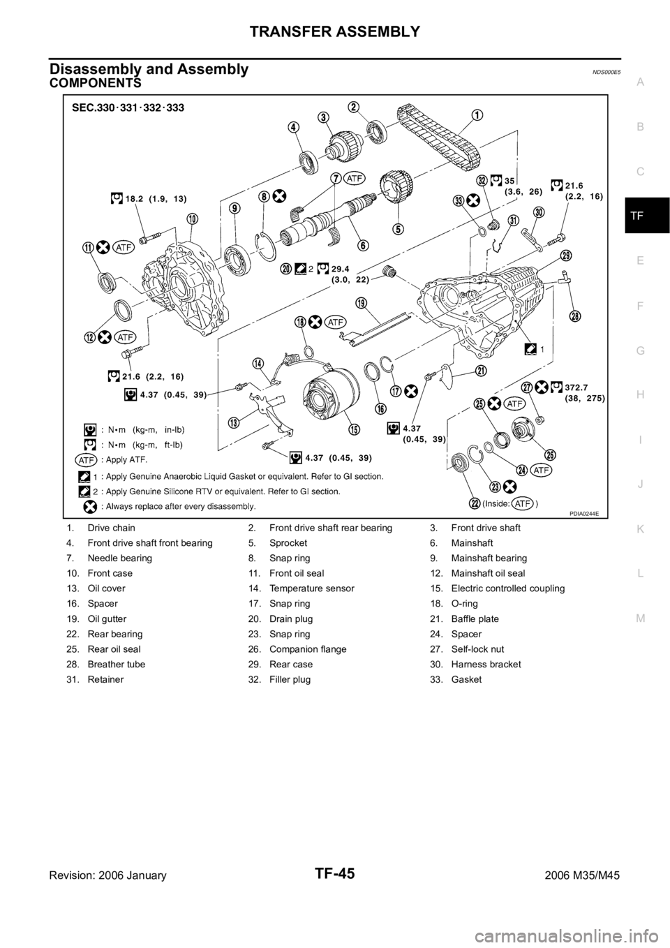
Disassembly and AssemblyNDS000E5
COMPONENTS
1. Drive chain 2. Front drive shaft rear bearing 3. Front drive shaft
4. Front drive shaft front bearing 5. Sprocket 6. Mainshaft
7. Needle bearing 8. Snap ring 9. Mainshaft bearing
10. Front case 11. Front oil seal 12. Mainshaft oil seal
13. Oil cover 14. Temperature sensor 15. Electric controlled coupling
16. Spacer 17. Snap ring 18. O-ring
19. Oil gutter 20. Drain plug 21. Baffle plate
22. Rear bearing 23. Snap ring 24. Spacer
25. Rear oil seal 26. Companion flange 27. Self-lock nut
28. Breather tube 29. Rear case 30. Harness bracket
31. Retainer 32. Filler plug 33. Gasket
PDIA0244E
Page 5513 of 5621

TF-48
TRANSFER ASSEMBLY
Revision: 2006 January2006 M35/M45
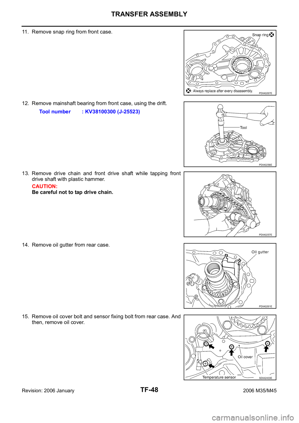
11. Remove snap ring from front case.
12. Remove mainshaft bearing from front case, using the drift.
13. Remove drive chain and front drive shaft while tapping front
drive shaft with plastic hammer.
CAUTION:
Be careful not to tap drive chain.
14. Remove oil gutter from rear case.
15. Remove oil cover bolt and sensor fixing bolt from rear case. And
then, remove oil cover.
PDIA0267E
Tool number : KV38100300 (J-25523)
PDIA0256E
PDIA0257E
PDIA0261E
SDIA2403E
Page 5519 of 5621

TF-54
TRANSFER ASSEMBLY
Revision: 2006 January2006 M35/M45
4. Install snap ring to rear case.
CAUTION:
Do not reuse snap ring.
5. Install mainshaft assembly to rear case, using the drift.
CAUTION:
ATF should be applied to contact surface of mainshaft and
rear bearing.
6. Install O-ring to transfer assembly harness connector.
CAUTION:
Do not reuse O-ring.
Apply ATF to O-ring.
7. Install transfer assembly harness connector into rear case.
8. Install retainer to transfer assembly harness connector.
9. Set temperature sensor and tighten bolt to the specified torque.
Refer to TF-45, "
COMPONENTS" .
10. Hold electric controlled coupling harness with oil cover hold
plate, install oil cover to rear case, and tighten bolt to the speci-
fied torque. Refer to TF-45, "
COMPONENTS" .
CAUTION:
The harness should be guided by a cut portion.
PDIA0263E
Tool number : ST35321000 ( — )
SDIA2368E
SDIA1597E
SDIA2404E
Page 5534 of 5621

LOW TIRE PRESSURE WARNING SYSTEM
WT-9
C
D
F
G
H
I
J
K
L
MA
B
WT
Revision: 2006 January2006 M35/M45
LOW TIRE PRESSURE WARNING SYSTEMPFP:40300
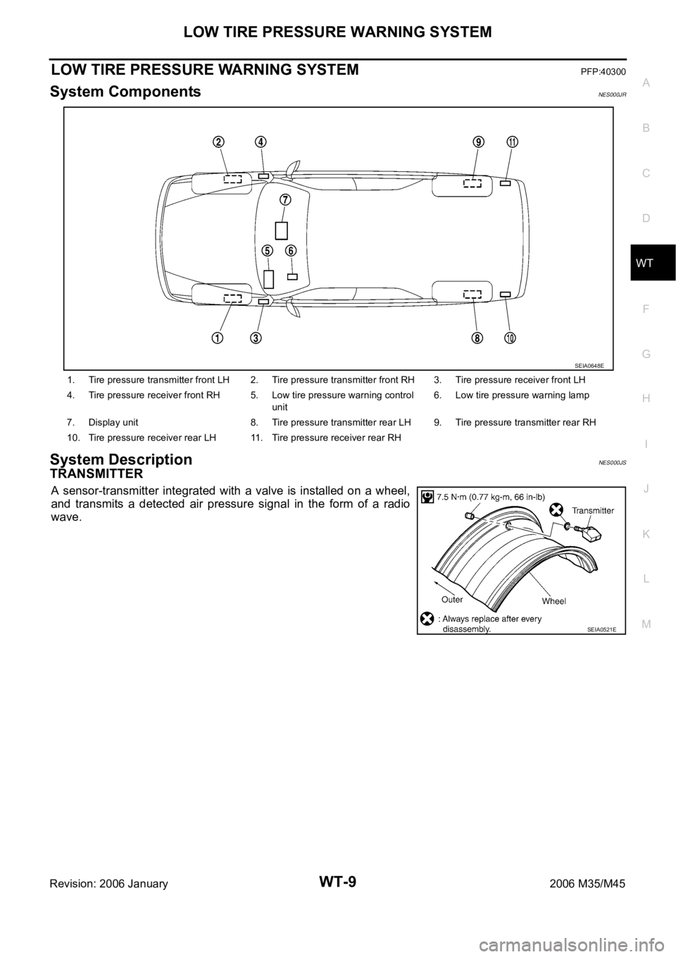
System ComponentsNES000JR
System DescriptionNES000JS
TRANSMITTER
A sensor-transmitter integrated with a valve is installed on a wheel,
and transmits a detected air pressure signal in the form of a radio
wave.
1. Tire pressure transmitter front LH 2. Tire pressure transmitter front RH 3. Tire pressure receiver front LH
4. Tire pressure receiver front RH 5. Low tire pressure warning control
unit6. Low tire pressure warning lamp
7. Display unit 8. Tire pressure transmitter rear LH 9. Tire pressure transmitter rear RH
10. Tire pressure receiver rear LH 11. Tire pressure receiver rear RH
SEIA0648E
SEIA0521E