2006 INFINITI M35 check
[x] Cancel search: checkPage 3464 of 5621

GI-1
GENERAL INFORMATION
A GENERAL INFORMATION
CONTENTS
C
D
E
F
G
H
I
J
K
L
MB
GI
SECTION GI
Revision: 2006 January2006 M35/M45
GENERAL INFORMATION
PRECAUTIONS .......................................................... 3
Description ............................................................... 3
Precautions for Supplemental Restraint System
(SRS) “AIR BAG” and “SEAT BELT PRE-TEN-
SIONER” .................................................................. 3
Precautions for NVIS/IVIS (NISSAN/INFINITI
VEHICLE IMMOBILIZER SYSTEM - NATS) (If
Equipped) ................................................................. 3
Precautions Necessary for Steering Wheel Rotation
After Battery Disconnect .......................................... 4
OPERATION PROCEDURE ................................. 4
Precautions for Procedures without Cowl Top Cover ..... 4
General Precautions ................................................ 4
Precautions for Three Way Catalyst ......................... 6
Precautions for Fuel (Unleaded Premium Gasoline
Recommended) ...................................................
..... 6
Precautions for Fuel (Unleaded Premium Gasoline
Required) ................................................................. 6
Precautions for Multiport Fuel Injection System or
Engine Control System ............................................ 7
Precautions for Hoses .............................................. 7
HOSE REMOVAL AND INSTALLATION ............... 7
HOSE CLAMPING ................................................ 7
Precautions for Engine Oils ...................................... 8
HEALTH PROTECTION PRECAUTIONS ............. 8
Precautions for Air Conditioning ............................... 8
HOW TO USE THIS MANUAL ................................... 9
Description ............................................................... 9
Terms ....................................................................... 9
Units ......................................................................... 9
Contents ................................................................... 9
Relation between Illustrations and Descriptions .... 10
Components ............................................................ 11
SYMBOLS ........................................................
.... 11
How to Follow Trouble Diagnoses .......................... 12
DESCRIPTION .................................................... 12
HOW TO FOLLOW TEST GROUPS IN TROU-
BLE DIAGNOSES ............................................... 12
HARNESS WIRE COLOR AND CONNECTOR
NUMBER INDICATION ....................................... 13KEY TO SYMBOLS SIGNIFYING MEASURE-
MENTS OR PROCEDURES ............................... 14
How to Read Wiring Diagrams ............................... 16
CONNECTOR SYMBOLS ................................... 16
SAMPLE/WIRING DIAGRAM - EXAMPL - .......... 17
DESCRIPTION .................................................... 18
Abbreviations .......................................................... 24
SERVICE INFORMATION FOR ELECTRICAL INCI-
DENT ......................................................................... 25
How to Check Terminal ........................................... 25
CONNECTOR AND TERMINAL PIN KIT ............ 25
HOW TO PROBE CONNECTORS ...................... 25
How to Perform Efficient Diagnosis for an Electrical
Incident ................................................................... 28
WORK FLOW ...................................................... 28
INCIDENT SIMULATION TESTS ........................ 28
CIRCUIT INSPECTION ....................................
... 31
Control Units and Electrical Parts ........................... 36
PRECAUTIONS .................................................. 36
CONSULT-II CHECKING SYSTEM .......................... 38
Description .............................................................. 38
Function and System Application ........................... 38
Nickel Metal Hydride Battery Replacement ............ 39
Checking Equipment .............................................. 39
CONSULT-II Start Procedure .................................. 39
CONSULT-II Data Link Connector (DLC) Circuit .... 40
INSPECTION PROCEDURE .............................. 40
CIRCUIT DIAGRAM ............................................ 41
LIFTING POINT ......................................................... 42
Special Service Tools ............................................. 42
Garage Jack and Safety Stand and 2-Pole Lift ....... 42
Board-On Lift .......................................................... 43
TOW TRUCK TOWING ............................................. 44
Tow Truck Towing ................................................... 44
2WD MODELS .................................................... 44
AWD MODELS .................................................... 45
Vehicle Recovery (Freeing a Stuck Vehicle) ........... 45
FRONT ................................................................ 45
REAR .................................................................. 45
AUTOMATIC TRANSMISSION ........................... 46
Page 3467 of 5621
GI-4
PRECAUTIONS
Revision: 2006 January2006 M35/M45
Precautions Necessary for Steering Wheel Rotation After Battery DisconnectNAS0008J
NOTE:
This Procedure is applied only to models with Intelligent Key system and NVIS/IVIS (NISSAN/INFINITI
VEHICLE IMMOBILIZER SYSTEM - NATS).
Remove and install all control units after disconnecting both battery cables with the ignition knob in the
LOCK position.
Always use CONSULT-II to perform self-diagnosis as a part of each function inspection after finishing
work. If DTC is detected, perform trouble diagnosis according to self-diagnostic results.
For models equipped with the Intelligent Key system and NVIS/IVIS, an electrically controlled steering lock
mechanism is adopted on the key cylinder.
For this reason, if the battery is disconnected or if the battery is discharged, the steering wheel will lock and
steering wheel rotation will become impossible.
If steering wheel rotation is required when battery power is interrupted, follow the procedure below before
starting the repair operation.
OPERATION PROCEDURE
1. Connect both battery cables.
NOTE:
Supply power using jumper cables if battery is discharged.
2. Use the Intelligent Key or mechanical key to turn the ignition switch to the
ACC position. At this time, the
steering lock will be released.
3. Disconnect both battery cables. The steering lock will remain released and the steering wheel can be
rotated.
4. Perform the necessary repair operation.
5. When the repair work is completed, return the ignition switch to the
LOCK position before connecting
the battery cables. (At this time, the steering lock mechanism will engage.)
6. Perform a self-diagnosis check of all control units using CONSULT-II.
Precautions for Procedures without Cowl Top CoverNAS00077
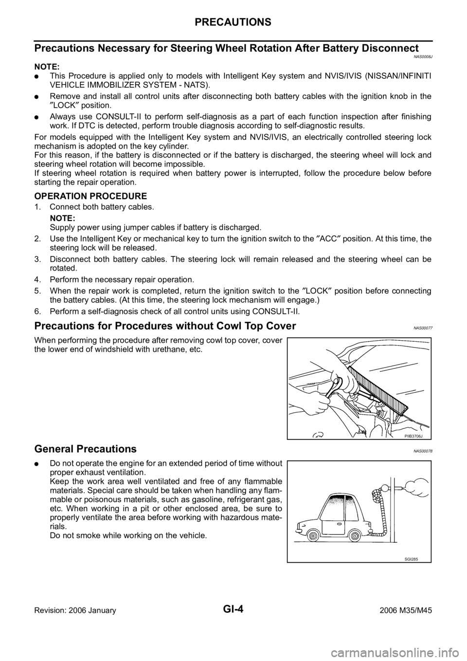
When performing the procedure after removing cowl top cover, cover
the lower end of windshield with urethane, etc.
General PrecautionsNAS00078
Do not operate the engine for an extended period of time without
proper exhaust ventilation.
Keep the work area well ventilated and free of any flammable
materials. Special care should be taken when handling any flam-
mable or poisonous materials, such as gasoline, refrigerant gas,
etc. When working in a pit or other enclosed area, be sure to
properly ventilate the area before working with hazardous mate-
rials.
Do not smoke while working on the vehicle.
PIIB3706J
SGI285
Page 3468 of 5621
PRECAUTIONS
GI-5
C
D
E
F
G
H
I
J
K
L
MB
GI
Revision: 2006 January2006 M35/M45
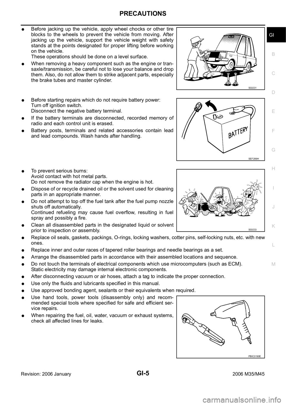
Before jacking up the vehicle, apply wheel chocks or other tire
blocks to the wheels to prevent the vehicle from moving. After
jacking up the vehicle, support the vehicle weight with safety
stands at the points designated for proper lifting before working
on the vehicle.
These operations should be done on a level surface.
When removing a heavy component such as the engine or tran-
saxle/transmission, be careful not to lose your balance and drop
them. Also, do not allow them to strike adjacent parts, especially
the brake tubes and master cylinder.
Before starting repairs which do not require battery power:
Turn off ignition switch.
Disconnect the negative battery terminal.
If the battery terminals are disconnected, recorded memory of
radio and each control unit is erased.
Battery posts, terminals and related accessories contain lead
and lead compounds. Wash hands after handling.
To prevent serious burns:
Avoid contact with hot metal parts.
Do not remove the radiator cap when the engine is hot.
Dispose of or recycle drained oil or the solvent used for cleaning
parts in an appropriate manner.
Do not attempt to top off the fuel tank after the fuel pump nozzle
shuts off automatically.
Continued refueling may cause fuel overflow, resulting in fuel
spray and possibly a fire.
Clean all disassembled parts in the designated liquid or solvent
prior to inspection or assembly.
Replace oil seals, gaskets, packings, O-rings, locking washers, cotter pins, self-locking nuts, etc. with new
ones.
Replace inner and outer races of tapered roller bearings and needle bearings as a set.
Arrange the disassembled parts in accordance with their assembled locations and sequence.
Do not touch the terminals of electrical components which use microcomputers (such as ECM).
Static electricity may damage internal electronic components.
After disconnecting vacuum or air hoses, attach a tag to indicate the proper connection.
Use only the fluids and lubricants specified in this manual.
Use approved bonding agent, sealants or their equivalents when required.
Use hand tools, power tools (disassembly only) and recom-
mended special tools where specified for safe and efficient ser-
vice repairs.
When repairing the fuel, oil, water, vacuum or exhaust systems,
check all affected lines for leaks.
SGI231
SEF289H
SGI233
PBIC0190E
Page 3469 of 5621
GI-6
PRECAUTIONS
Revision: 2006 January2006 M35/M45
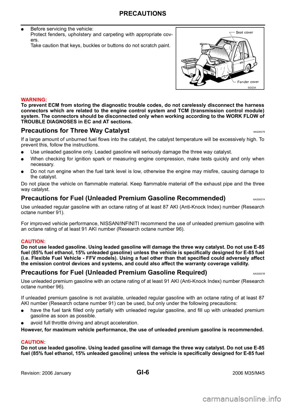
Before servicing the vehicle:
Protect fenders, upholstery and carpeting with appropriate cov-
ers.
Take caution that keys, buckles or buttons do not scratch paint.
WAR NING :
To prevent ECM from storing the diagnostic trouble codes, do not carelessly disconnect the harness
connectors which are related to the engine control system and TCM (transmission control module)
system. The connectors should be disconnected only when working according to the WORK FLOW of
TROUBLE DIAGNOSES in EC and AT sections.
Precautions for Three Way CatalystNAS00079
If a large amount of unburned fuel flows into the catalyst, the catalyst temperature will be excessively high. To
prevent this, follow the instructions.
Use unleaded gasoline only. Leaded gasoline will seriously damage the three way catalyst.
When checking for ignition spark or measuring engine compression, make tests quickly and only when
necessary.
Do not run engine when the fuel tank level is low, otherwise the engine may misfire, causing damage to
the catalyst.
Do not place the vehicle on flammable material. Keep flammable material off the exhaust pipe and the three
way catalyst.
Precautions for Fuel (Unleaded Premium Gasoline Recommended)NAS0007A
Use unleaded regular gasoline with an octane rating of at least 87 AKI (Anti-Knock Index) number (Research
octane number 91).
For improved vehicle performance, NISSAN/INFINITI recommend the use of unleaded premium gasoline with
an octane rating of at least 91 AKI number (Research octane number 96).
CAUTION:
Do not use leaded gasoline. Using leaded gasoline will damage the three way catalyst. Do not use E-85
fuel (85% fuel ethanol, 15% unleaded gasoline) unless the vehicle is specifically designed for E-85 fuel
(i.e. Flexible Fuel Vehicle - FFV models). Using a fuel other than that specified could adversely affect
the emission control devices and systems, and could also affect the warranty coverage validity.
Precautions for Fuel (Unleaded Premium Gasoline Required)NAS0007B
Use unleaded premium gasoline with an octane rating of at least 91 AKI (Anti-Knock Index) number (Research
octane number 96).
If unleaded premium gasoline is not available, unleaded regular gasoline with an octane rating of at least 87
AKI number (Research octane number 91) can be used, but only under the following precautions:
have the fuel tank filled only partially with unleaded regular gasoline, and fill up with unleaded premium
gasoline as soon as possible.
avoid full throttle driving and abrupt acceleration.
However, for maximum vehicle performance, the use of unleaded premium gasoline is recommended.
CAUTION:
Do not use leaded gasoline. Using leaded gasoline will damage the three way catalyst. Do not use E-85
fuel (85% fuel ethanol, 15% unleaded gasoline) unless the vehicle is specifically designed for E-85 fuel
SGI234
Page 3475 of 5621
GI-12
HOW TO USE THIS MANUAL
Revision: 2006 January2006 M35/M45
How to Follow Trouble DiagnosesNAS0007M
DESCRIPTION
NOTICE:
Trouble diagnoses indicate work procedures required to diagnose problems effectively. Observe the following
instructions before diagnosing.
1.Before performing trouble diagnoses, read the “Preliminary Check”, the “Symptom Chart” or the
“Work Flow”.
2.After repairs, re-check that the problem has been completely eliminated.
3.Refer to Component Parts and Harness Connector Location for the Systems described in each
section for identification/location of components and harness connectors.
4.Refer to the Circuit Diagram for quick pinpoint check.
If you need to check circuit continuity between harness connectors in more detail, such as when a
sub-harness is used, refer to Wiring Diagram in each individual section and Harness Layout in PG
section for identification of harness connectors.
5.When checking circuit continuity, ignition switch should be OFF.
6.Before checking voltage at connectors, check battery voltage.
7.After accomplishing the Diagnostic Procedures and Electrical Components Inspection, make sure
that all harness connectors are reconnected as they were.
HOW TO FOLLOW TEST GROUPS IN TROUBLE DIAGNOSES
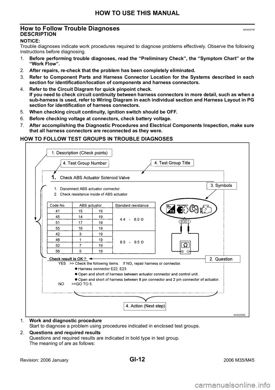
1.Work and diagnostic procedure
Start to diagnose a problem using procedures indicated in enclosed test groups.
2.Questions and required results
Questions and required results are indicated in bold type in test group.
The meaning of are as follows:
SAIA0256E
Page 3488 of 5621

SERVICE INFORMATION FOR ELECTRICAL INCIDENT
GI-25
C
D
E
F
G
H
I
J
K
L
MB
GI
Revision: 2006 January2006 M35/M45
SERVICE INFORMATION FOR ELECTRICAL INCIDENTPFP:00000
How to Check Terminal NAS0007P
CONNECTOR AND TERMINAL PIN KIT
Use the connector and terminal pin kits listed below when replacing connectors or terminals.
The connector and terminal pin kits contain some of the most commonly used NISSAN/INFINITI connectors
and terminals. For detailed connector and terminal pin replacement procedures, refer to the latest NISSAN/
INFINITI CONNECTOR AND TERMINAL PIN SERVICE MANUAL.
HOW TO PROBE CONNECTORS
Connector damage and an intermittent connection can result from improperly probing of the connector during
circuit checks.
The probe of a digital multimeter (DMM) may not correctly fit the connector cavity. To correctly probe the con-
nector, follow the procedures below using a “T” pin. For the best contact grasp the “T” pin using an alligator
clip.
Probing from Harness Side
Standard type (not waterproof type) connector should be probed
from harness side with “T” pin.
If the connector has a rear cover such as a ECM connector,
remove the rear cover before probing the terminal.
Do not probe waterproof connector from harness side. Damage
to the seal between wire and connector may result.
Probing from Terminal Side
FEMALE TERMINAL
There is a small notch above each female terminal. Probe each
terminal with the “T” pin through the notch.
Do not insert any object other than the same type male terminal
into female terminal.
Tool number
(Kent-Moore No.)
To o l n a m eDescription
-
(J38751-95NI)
Connector and terminal
pin kit (NISSAN)
-
(J38751-95INF)
Connector and terminal
pin kit (INFINITI)
-
(J42992-98KIT)
OBD and terminal repair
kit
-
(J42992-2000UPD)
OBD-II Connector Kit
Update
WAIA0004EWAIA0005E
SGI841
SEL265V
Page 3489 of 5621
GI-26
SERVICE INFORMATION FOR ELECTRICAL INCIDENT
Revision: 2006 January2006 M35/M45
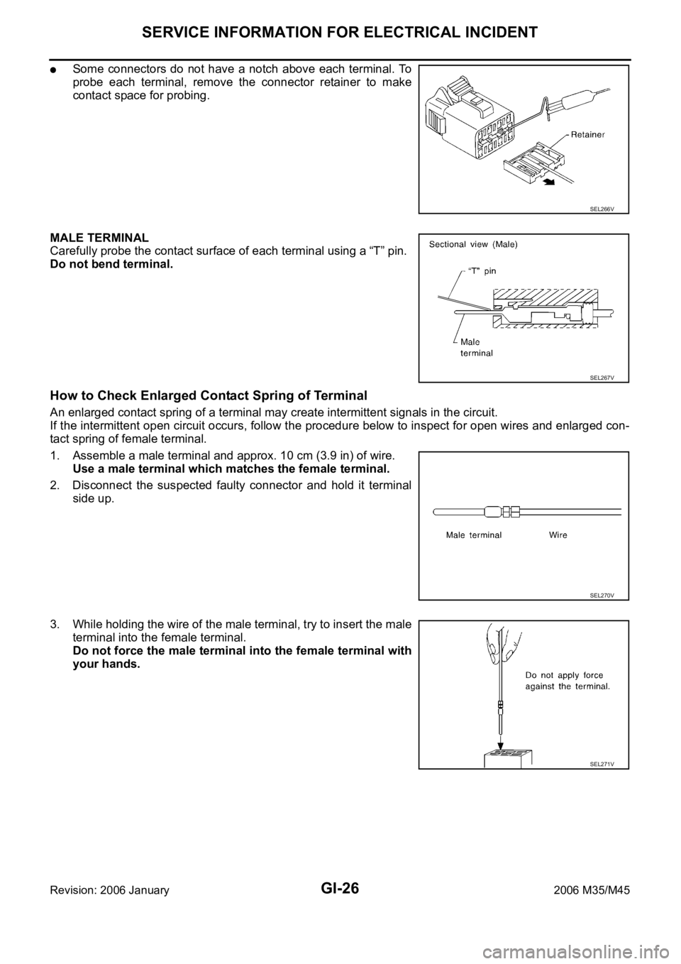
Some connectors do not have a notch above each terminal. To
probe each terminal, remove the connector retainer to make
contact space for probing.
MALE TERMINAL
Carefully probe the contact surface of each terminal using a “T” pin.
Do not bend terminal.
How to Check Enlarged Contact Spring of Terminal
An enlarged contact spring of a terminal may create intermittent signals in the circuit.
If the intermittent open circuit occurs, follow the procedure below to inspect for open wires and enlarged con-
tact spring of female terminal.
1. Assemble a male terminal and approx. 10 cm (3.9 in) of wire.
Use a male terminal which matches the female terminal.
2. Disconnect the suspected faulty connector and hold it terminal
side up.
3. While holding the wire of the male terminal, try to insert the male
terminal into the female terminal.
Do not force the male terminal into the female terminal with
your hands.
SEL266V
SEL267V
SEL270V
SEL271V
Page 3490 of 5621
SERVICE INFORMATION FOR ELECTRICAL INCIDENT
GI-27
C
D
E
F
G
H
I
J
K
L
MB
GI
Revision: 2006 January2006 M35/M45
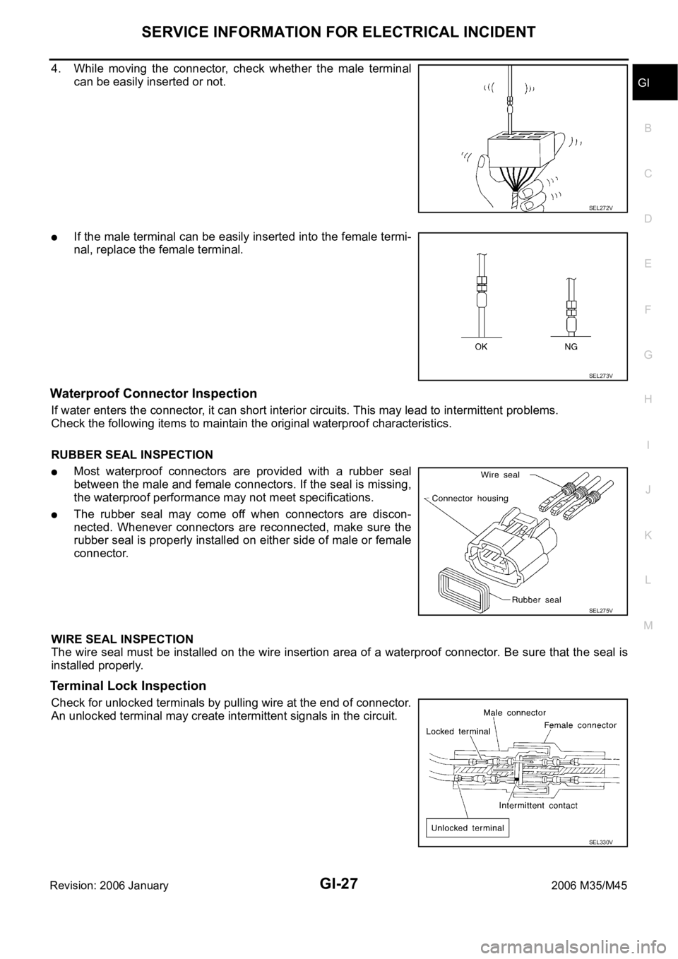
4. While moving the connector, check whether the male terminal
can be easily inserted or not.
If the male terminal can be easily inserted into the female termi-
nal, replace the female terminal.
Waterproof Connector Inspection
If water enters the connector, it can short interior circuits. This may lead to intermittent problems.
Check the following items to maintain the original waterproof characteristics.
RUBBER SEAL INSPECTION
Most waterproof connectors are provided with a rubber seal
between the male and female connectors. If the seal is missing,
the waterproof performance may not meet specifications.
The rubber seal may come off when connectors are discon-
nected. Whenever connectors are reconnected, make sure the
rubber seal is properly installed on either side of male or female
connector.
WIRE SEAL INSPECTION
The wire seal must be installed on the wire insertion area of a waterproof connector. Be sure that the seal is
installed properly.
Terminal Lock Inspection
Check for unlocked terminals by pulling wire at the end of connector.
An unlocked terminal may create intermittent signals in the circuit.
SEL272V
SEL273V
SEL275V
SEL330V