2006 INFINITI M35 check
[x] Cancel search: checkPage 3525 of 5621

GW-6
SQUEAK AND RATTLE TROUBLE DIAGNOSES
Revision: 2006 January2006 M35/M45
DUPLICATE THE NOISE AND TEST DRIVE
If possible, drive the vehicle with the customer until the noise is duplicated. Note any additional information on
the Diagnostic Worksheet regarding the conditions or location of the noise. This information can be used to
duplicate the same conditions when you confirm the repair.
If the noise can be duplicated easily during the test drive, to help identify the source of the noise, try to dupli-
cate the noise with the vehicle stopped by doing one or all of the following:
1) Close a door.
2) Tap or push/pull around the area where the noise appears to be coming from.
3) Rev the engine.
4) Use a floor jack to recreate vehicle “twist”.
5) At idle, apply engine load (electrical load, half-clutch on M/T models, drive position on A/T models).
6) Raise the vehicle on a hoist and hit a tire with a rubber hammer.
Drive the vehicle and attempt to duplicate the conditions the customer states exist when the noise occurs.
If it is difficult to duplicate the noise, drive the vehicle slowly on an undulating or rough road to stress the
vehicle body.
CHECK RELATED SERVICE BULLETINS
After verifying the customer concern or symptom, check ASIST for Technical Service Bulletins (TSBs) related
to that concern or symptom.
If a TSB relates to the symptom, follow the procedure to repair the noise.
LOCATE THE NOISE AND IDENTIFY THE ROOT CAUSE
1. Narrow down the noise to a general area. To help pinpoint the source of the noise, use a listening tool
(Chassis Ear: J-39570, Engine Ear and mechanics stethoscope).
2. Narrow down the noise to a more specific area and identify the cause of the noise by:
removing the components in the area that you suspect the noise is coming from.
Do not use too much force when removing clips and fasteners, otherwise clips and fastener can be broken
or lost during the repair, resulting in the creation of new noise.
tapping or pushing/pulling the component that you suspect is causing the noise.
Do not tap or push/pull the component with excessive force, otherwise the noise will be eliminated only
temporarily.
feeling for a vibration with your hand by touching the component(s) that you suspect is (are) causing the
noise.
placing a piece of paper between components that you suspect are causing the noise.
looking for loose components and contact marks.
Refer to GW-7, "
Generic Squeak and Rattle Troubleshooting" .
REPAIR THE CAUSE
If the cause is a loose component, tighten the component securely.
If the cause is insufficient clearance between components:
–separate components by repositioning or loosening and retightening the component, if possible.
–insulate components with a suitable insulator such as urethane pads, foam blocks, felt cloth tape or ure-
thane tape. A Nissan Squeak and Rattle Kit (J-43980) is available through your authorized Nissan Parts
Department.
CAUTION:
Do not use excessive force as many components are constructed of plastic and may be damaged.
NOTE:
Always check with the Parts Department for the latest parts information.
The following materials are contained in the Nissan Squeak and Rattle Kit (J-43980). Each item can be
ordered separately as needed.
URETHANE PADS [1.5 mm (0.059 in) thick]
Insulates connectors, harness, etc.
76268-9E005: 100
135 mm (3.945.31 in)/76884-71L01: 6085 mm (2.363.35 in)/76884-
71L02: 15
25 mm (0.590.98 in)
INSULATOR (Foam blocks)
Insulates components from contact. Can be used to fill space behind a panel.
73982-9E000: 45 mm (1.77 in) thick, 50
50 mm (1.971.97 in)/73982-
50Y00: 10 mm (0.39 in) thick, 50
50 mm (1.971.97 in)
Page 3526 of 5621

SQUEAK AND RATTLE TROUBLE DIAGNOSES
GW-7
C
D
E
F
G
H
J
K
L
MA
B
GW
Revision: 2006 January2006 M35/M45
INSULATOR (Light foam block)
80845-71L00: 30 mm (1.18 in) thick, 30
50 mm (1.181.97 in)
FELT CLOTHTAPE
Used to insulate where movement does not occur. Ideal for instrument panel applications.
68370-4B000: 15
25 mm (0.590.98 in) pad/68239-13E00: 5 mm (0.20 in) wide tape roll
The following materials, not found in the kit, can also be used to repair squeaks and rattles.
UHMW (TEFLON) TAPE
Insulates where slight movement is present. Ideal for instrument panel applications.
SILICONE GREASE
Used in place of UHMW tape that will be visible or not fit. Will only last a few months.
SILICONE SPRAY
Use when grease cannot be applied.
DUCT TAPE
Use to eliminate movement.
CONFIRM THE REPAIR
Confirm that the cause of a noise is repaired by test driving the vehicle. Operate the vehicle under the same
conditions as when the noise originally occurred. Refer to the notes on the Diagnostic Worksheet.
Generic Squeak and Rattle TroubleshootingNIS0021C
Refer to Table of Contents for specific component removal and installation information.
INSTRUMENT PANEL
Most incidents are caused by contact and movement between:
1. The cluster lid A and instrument panel
2. Acrylic lens and combination meter housing
3. Instrument panel to front pillar garnish
4. Instrument panel to windshield
5. Instrument panel mounting pins
6. Wiring harnesses behind the combination meter
7. A/C defroster duct and duct joint
These incidents can usually be located by tapping or moving the components to duplicate the noise or by
pressing on the components while driving to stop the noise. Most of these incidents can be repaired by apply-
ing felt cloth tape or silicon spray (in hard to reach areas). Urethane pads can be used to insulate wiring har-
ness.
CAUTION:
Do not use silicone spray to isolate a squeak or rattle. If you saturate the area with silicone, you will
not be able to recheck the repair.
CENTER CONSOLE
Components to pay attention to include:
1. Shifter assembly cover to finisher
2. A/C control unit and cluster lid C
3. Wiring harnesses behind audio and A/C control unit
The instrument panel repair and isolation procedures also apply to the center console.
DOORS
Pay attention to the:
1. Finisher and inner panel making a slapping noise
2. Inside handle escutcheon to door finisher
3. Wiring harnesses tapping
4. Door striker out of alignment causing a popping noise on starts and stops
Tapping or moving the components or pressing on them while driving to duplicate the conditions can isolate
many of these incidents. You can usually insulate the areas with felt cloth tape or insulator foam blocks from
the Nissan Squeak and Rattle Kit (J-43980) to repair the noise.
Page 3549 of 5621
GW-30
POWER WINDOW SYSTEM
Revision: 2006 January2006 M35/M45
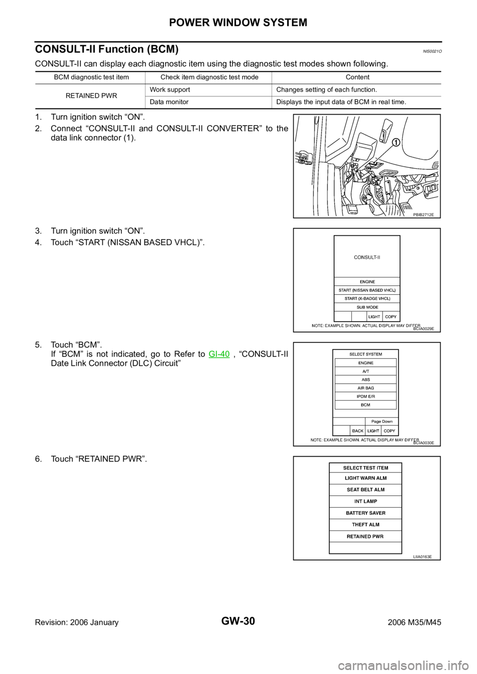
CONSULT-II Function (BCM)NIS0021O
CONSULT-II can display each diagnostic item using the diagnostic test modes shown following.
1. Turn ignition switch “ON”.
2. Connect “CONSULT-II and CONSULT-II CONVERTER” to the
data link connector (1).
3. Turn ignition switch “ON”.
4. Touch “START (NISSAN BASED VHCL)”.
5. Touch “BCM”.
If “BCM” is not indicated, go to Refer to GI-40
, “CONSULT-II
Date Link Connector (DLC) Circuit”
6. Touch “RETAINED PWR”.
BCM diagnostic test item Check item diagnostic test mode Content
RETAINED PWRWork support Changes setting of each function.
Data monitor Displays the input data of BCM in real time.
PBIB2712E
BCIA0029E
BCIA0030E
LIIA0163E
Page 3551 of 5621
GW-32
POWER WINDOW SYSTEM
Revision: 2006 January2006 M35/M45
Work FlowNIS0021P
1. Check the symptom and customer's requests.
2. Understand the outline of system. Refer to GW-13, "
System Description"
3. According to the trouble diagnosis chart, repair or replace the cause of the malfunction.
Refer to GW-32, "
Trouble Diagnosis Symptom Chart"
4. Does power window system operate normally? Yes, GO TO 5, If No, GO TO 3.
5. INSPECTION END
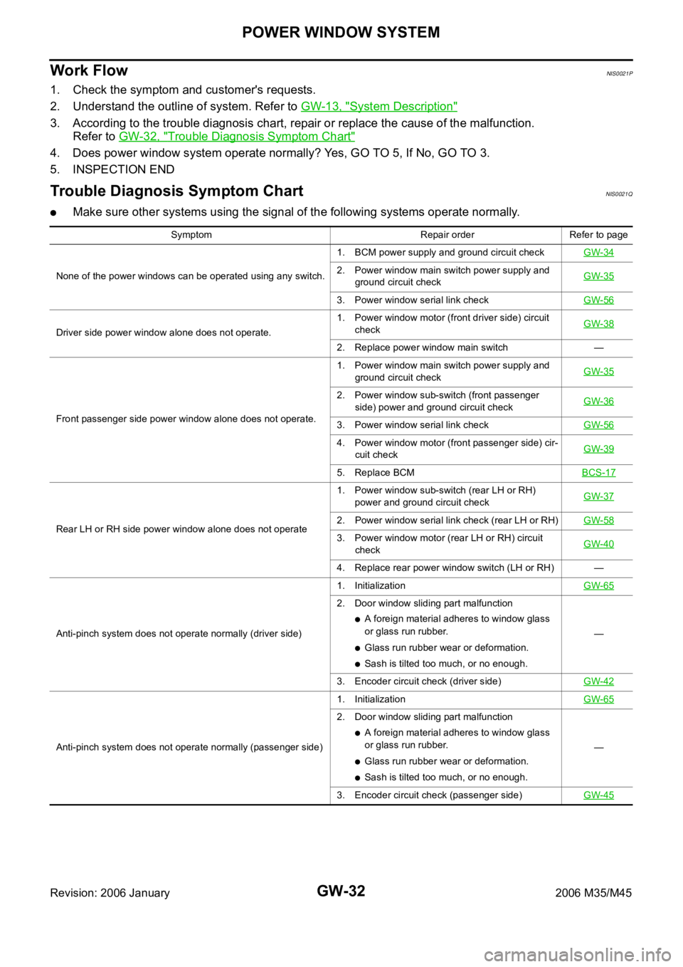
Trouble Diagnosis Symptom ChartNIS0021Q
Make sure other systems using the signal of the following systems operate normally.
Symptom Repair order Refer to page
None of the power windows can be operated using any switch.1. BCM power supply and ground circuit checkGW-34
2. Power window main switch power supply and
ground circuit checkGW-35
3. Power window serial link checkGW-56
Driver side power window alone does not operate.1. Power window motor (front driver side) circuit
checkGW-38
2. Replace power window main switch —
Front passenger side power window alone does not operate.1. Power window main switch power supply and
ground circuit checkGW-35
2. Power window sub-switch (front passenger
side) power and ground circuit checkGW-36
3. Power window serial link checkGW-56
4. Power window motor (front passenger side) cir-
cuit checkGW-39
5. Replace BCMBCS-17
Rear LH or RH side power window alone does not operate1. Power window sub-switch (rear LH or RH)
power and ground circuit checkGW-372. Power window serial link check (rear LH or RH)GW-58
3. Power window motor (rear LH or RH) circuit
checkGW-40
4. Replace rear power window switch (LH or RH) —
Anti-pinch system does not operate normally (driver side)1. InitializationGW-65
2. Door window sliding part malfunction
A foreign material adheres to window glass
or glass run rubber.
Glass run rubber wear or deformation.
Sash is tilted too much, or no enough.—
3. Encoder circuit check (driver side)GW-42
Anti-pinch system does not operate normally (passenger side)1. InitializationGW-65
2. Door window sliding part malfunction
A foreign material adheres to window glass
or glass run rubber.
Glass run rubber wear or deformation.
Sash is tilted too much, or no enough.—
3. Encoder circuit check (passenger side)GW-45
Page 3552 of 5621
POWER WINDOW SYSTEM
GW-33
C
D
E
F
G
H
J
K
L
MA
B
GW
Revision: 2006 January2006 M35/M45
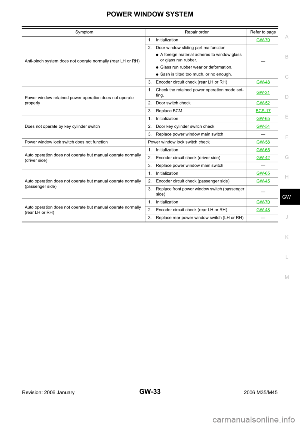
Anti-pinch system does not operate normally (rear LH or RH)1. InitializationGW-70
2. Door window sliding part malfunction
A foreign material adheres to window glass
or glass run rubber.
Glass run rubber wear or deformation.
Sash is tilted too much, or no enough.—
3. Encoder circuit check (rear LH or RH)GW-48
Power window retained power operation does not operate
properly1. Check the retained power operation mode set-
ting.GW-31
2. Door switch checkGW-52
3. Replace BCM.BCS-17
Does not operate by key cylinder switch1. InitializationGW-652. Door key cylinder switch checkGW-54
3. Replace power window main switch —
Power window lock switch does not function Power window lock switch checkGW-58
Auto operation does not operate but manual operate normally
(driver side)1. InitializationGW-652. Encoder circuit check (driver side)GW-42
3. Replace power window main switch —
Auto operation does not operate but manual operate normally
(passenger side)1. InitializationGW-65
2. Encoder circuit check (passenger side)GW-45
3. Replace front power window switch (passenger
side)—
Auto operation does not operate but manual operate normally
(rear LH or RH)1. InitializationGW-70
2. Encoder circuit check (rear LH or RH)GW-48
3. Replace rear power window switch (LH or RH) — Symptom Repair order Refer to page
Page 3553 of 5621
![INFINITI M35 2006 Factory Service Manual GW-34
POWER WINDOW SYSTEM
Revision: 2006 January2006 M35/M45
BCM Power Supply and Ground Circuit CheckNIS0021R
1. CHECK FUSE
Check 15A fuse [No. 1, located in fuse block (J/B)]
Check 10A fuse [No. 21, INFINITI M35 2006 Factory Service Manual GW-34
POWER WINDOW SYSTEM
Revision: 2006 January2006 M35/M45
BCM Power Supply and Ground Circuit CheckNIS0021R
1. CHECK FUSE
Check 15A fuse [No. 1, located in fuse block (J/B)]
Check 10A fuse [No. 21,](/manual-img/42/57023/w960_57023-3552.png)
GW-34
POWER WINDOW SYSTEM
Revision: 2006 January2006 M35/M45
BCM Power Supply and Ground Circuit CheckNIS0021R
1. CHECK FUSE
Check 15A fuse [No. 1, located in fuse block (J/B)]
Check 10A fuse [No. 21, located in fuse block (J/B)]
Check 50A fusible link (letter F , located in the fuse and fusible link box).
NOTE:
Refer to GW-13, "
Component Parts and Harness Connector Location" .
OK or NG
OK >> GO TO 2.
NG >> If fuse is blown out, be sure to eliminate cause of malfunction before installing new fuse. Refer to
PG-3, "
POWER SUPPLY ROUTING CIRCUIT" .
2. CHECK POWER SUPPLY CIRCUIT
Check voltage between BCM connector and ground.
OK or NG
OK >> GO TO 3.
NG >> Check BCM power supply circuit for open or short.
3. CHECK GROUND CIRCUIT
1. Turn ignition switch OFF.
2. Disconnect BCM connector.
3. Check continuity between BCM connector and ground.
OK or NG
OK >> Power supply and ground circuit are OK.
NG >> Check BCM ground circuit for open or short.
Te r m i n a l s
Condition of
ignition switchVoltage (V)
(Approx.) (+)
(–)
BCM connector Terminal
M1 38
GroundON
Battery voltage
M242
OFF
55
PIIB5934E
BCM connector Terminal
GroundContinuity
M2 52 Yes
PIIB5935E
Page 3554 of 5621
POWER WINDOW SYSTEM
GW-35
C
D
E
F
G
H
J
K
L
MA
B
GW
Revision: 2006 January2006 M35/M45
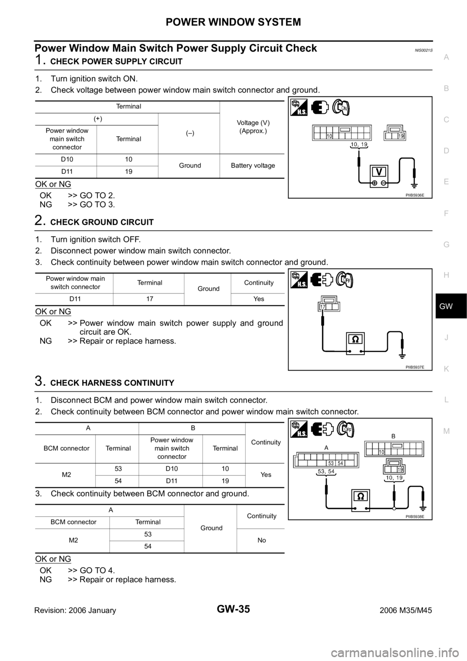
Power Window Main Switch Power Supply Circuit Check NIS0021S
1. CHECK POWER SUPPLY CIRCUIT
1. Turn ignition switch ON.
2. Check voltage between power window main switch connector and ground.
OK or NG
OK >> GO TO 2.
NG >> GO TO 3.
2. CHECK GROUND CIRCUIT
1. Turn ignition switch OFF.
2. Disconnect power window main switch connector.
3. Check continuity between power window main switch connector and ground.
OK or NG
OK >> Power window main switch power supply and ground
circuit are OK.
NG >> Repair or replace harness.
3. CHECK HARNESS CONTINUITY
1. Disconnect BCM and power window main switch connector.
2. Check continuity between BCM connector and power window main switch connector.
3. Check continuity between BCM connector and ground.
OK or NG
OK >> GO TO 4.
NG >> Repair or replace harness.
Terminal
Voltage (V)
(Approx.) (+)
(–) Power window
main switch
connectorTerminal
D10 10
Ground Battery voltage
D11 19
PIIB5936E
Power window main
switch connectorTerminal
GroundContinuity
D11 17 Yes
PIIB5937E
AB
Continuity
BCM connector TerminalPower window
main switch
connectorTerminal
M253 D10 10
Ye s
54 D11 19
A
GroundContinuity
BCM connector Terminal
M253
No
54
PIIB5938E
Page 3555 of 5621
GW-36
POWER WINDOW SYSTEM
Revision: 2006 January2006 M35/M45
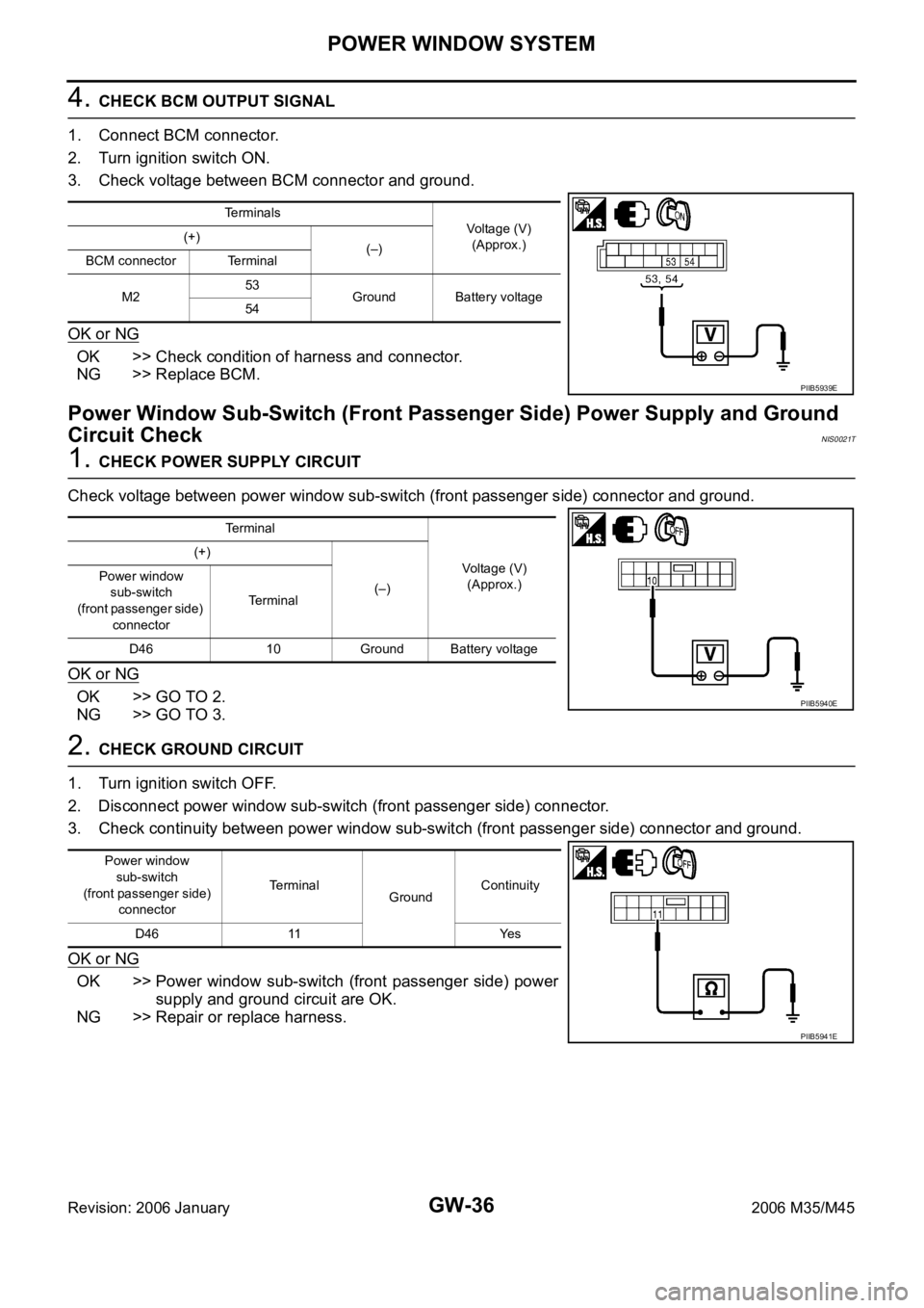
4. CHECK BCM OUTPUT SIGNAL
1. Connect BCM connector.
2. Turn ignition switch ON.
3. Check voltage between BCM connector and ground.
OK or NG
OK >> Check condition of harness and connector.
NG >> Replace BCM.
Power Window Sub-Switch (Front Passenger Side) Power Supply and Ground
Circuit Check
NIS0021T
1. CHECK POWER SUPPLY CIRCUIT
Check voltage between power window sub-switch (front passenger side) connector and ground.
OK or NG
OK >> GO TO 2.
NG >> GO TO 3.
2. CHECK GROUND CIRCUIT
1. Turn ignition switch OFF.
2. Disconnect power window sub-switch (front passenger side) connector.
3. Check continuity between power window sub-switch (front passenger side) connector and ground.
OK or NG
OK >> Power window sub-switch (front passenger side) power
supply and ground circuit are OK.
NG >> Repair or replace harness.
Terminals
Voltage (V)
(Approx.) (+)
(–)
BCM connector Terminal
M253
Ground Battery voltage
54
PIIB5939E
Terminal
Voltage (V)
(Approx.) (+)
(–) Power window
sub-switch
(front passenger side)
connectorTerminal
D46 10 Ground Battery voltage
PIIB5940E
Power window
sub-switch
(front passenger side)
connectorTerminal
GroundContinuity
D46 11 Yes
PIIB5941E