2006 INFINITI M35 check
[x] Cancel search: checkPage 3588 of 5621
REAR DOOR GLASS AND REGULATOR
GW-69
C
D
E
F
G
H
J
K
L
MA
B
GW
Revision: 2006 January2006 M35/M45
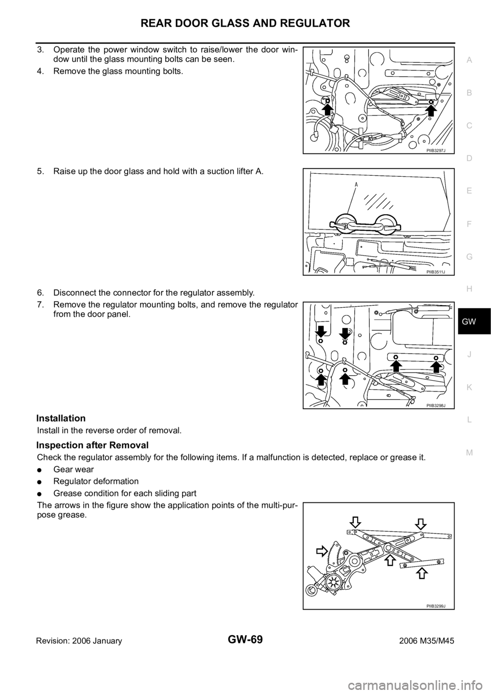
3. Operate the power window switch to raise/lower the door win-
dow until the glass mounting bolts can be seen.
4. Remove the glass mounting bolts.
5. Raise up the door glass and hold with a suction lifter A.
6. Disconnect the connector for the regulator assembly.
7. Remove the regulator mounting bolts, and remove the regulator
from the door panel.
Installation
Install in the reverse order of removal.
Inspection after Removal
Check the regulator assembly for the following items. If a malfunction is detected, replace or grease it.
Gear wear
Regulator deformation
Grease condition for each sliding part
The arrows in the figure show the application points of the multi-pur-
pose grease.
PIIB3297J
PIIB3511J
PIIB3298J
PIIB3299J
Page 3589 of 5621

GW-70
REAR DOOR GLASS AND REGULATOR
Revision: 2006 January2006 M35/M45
Disassembly and AssemblyNIS0022C
REGULATOR ASSEMBLY
Disassembly
Remove power window motor from regulator assembly.
Assembly
Assemble in the reverse order of disassembly.
Inspection after InstallationNIS0022D
SYSTEM INITIALIZATION
If any of the following work has been done, initialize the system.
Electric power sauce to power window switch or motor is interrupted by broken fuse or disconnecting bat-
tery cable, etc.
Removal and installation of the regulator assembly.
Removal and installation of the motor from the regulator assembly.
Removal and installation of the harness connector of the power window switch.
Operate the regulator assembly as a unit.
Removal and installation of the door glass.
Removal and installation of the door glass run.
Initialization
After installing each component to the vehicle, follow the steps below.
1. Disconnect the minus terminal of battery or disconnect power window switch's harness connector tempo-
rarily, then reconnect after at least 1 minute.
2. Turn ignition switch ON.
3. Open the window to its full width by operating the power window switch. (Exclude this pocedure if the win-
dow is already fully opened)
4. Fully draw the power window switch in up direction (auto close position) and hold, keep holding the switch
even when window is completely closed and then release afeter 3 second has passed.
5. Inspection of the anti-pinch system function.
NOTE:
Initialization may be cancelled with continuous opening and closing operation.In this case, initialize the
system.
INSPECT THE FUNCTION OF THE ANTI-PINCH SYSTEM
1. Fully open the door glass.
2. Place a wooden piece (wooden hammer handle etc.) at near fully closed position.
3. Carry out fully closing operation with auto up switch.
Check that the glass reverses without pinching the wooden piece, is lowered approx.150mm (5.91in) or
for 2 seconds and then stops.
The glass should not be raised with power window main switch operated while it is reversing or lowering.
CAUTION:
Do not inspect with pinching a part of worker's body, a hand etc. Work carefully not to be pinched.
Check that auto up function is normal before inspection following the system initialization.
FITTING INSPECTION
Make sure the glass is securely fit into the glass run groove.
Lower the glass slightly [approx. 10 to 20 mm (0.39 to 0.79 in)], and make sure the clearance to the sash
is parallel. If the clearance between the glass and sash is not parallel, loosen the regulator mounting bolts,
guide rail mounting bolts, and glass and carrier plate mounting bolts to correct the glass position.
Page 3603 of 5621
GW-84
REAR WINDOW DEFOGGER
Revision: 2006 January2006 M35/M45
Work FlowNIS0022P
1. Check the symptom and customer's requests.
2. Understand the outline of system. Refer to GW-73, "
System Description" .
3. According to the trouble diagnosis chart, repair or replace the cause of the malfunction. Refer to GW-84,
"Trouble Diagnoses Symptom Chart" .
4. Does rear window defogger operate normally? YES: GO TO 5, NO: GO TO 3.
5. INSPECTION END.
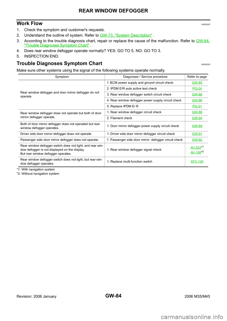
Trouble Diagnoses Symptom ChartNIS0022Q
Make sure other systems using the signal of the following systems operate normally.
*1: With navigation system
*2: Without navigation systemSymptom Diagnoses / Service procedure Refer to page
Rear window defogger and door mirror defogger do not
operate. 1. BCM power supply and ground circuit check.GW-85
2. IPDM E/R auto active test checkPG-24
3. Rear window defogger switch circuit checkGW-86
4. Rear window defogger power supply circuit checkGW-86
5. Replace IPDM E/ RPG-31
Rear window defogger does not operate but both of door
mirror defogger operate.1. Rear window defogger circuit checkGW-88
2. Filament checkGW-94
Both of door mirror defogger does not operated but rear
window defogger operates. 1. Door mirror defogger power supply circuit checkGW-89
Driver side door mirror defogger does not operate. 1. Driver side door mirror defogger circuit checkGW-91
Passenger side door mirror defogger does not operate. 1. Passenger side door mirror defogger circuit checkGW-92
Rear window defogger switch does not light, and rear win-
dow defogger is not displayed on the display.
But rear window defogger operates. 1. Rear window defogger signal checkAV-253*1
AV-108*2
Rear window defogger switch does not light, but rear win-
dow defogger operates1. Replace multi-function switchATC-124
Page 3604 of 5621
REAR WINDOW DEFOGGER
GW-85
C
D
E
F
G
H
J
K
L
MA
B
GW
Revision: 2006 January2006 M35/M45
BCM Power Supply and Ground Circuit CheckNIS0022R
First perform the “SELF-DIAG RESULTS” in “BCM” with CONSULT-II, when perform the each trouble
diagnosis. Refer to BCS-15, "
CAN Communication Inspection Using CONSULT-II (Self-Diagnosis)" .
1. CHECK FUSE
Check 15A fuse [No.1, located in the fuse block (J/B)]
Check 10A fuse [No.21, located in the fuse block (J/B)]
Check 50A fusible link (letter F located in the fuse and fusible link box).
NOTE:
Refer to GW-73, "
Component Parts and Harness Connector Location" .
OK or NG
OK >> GO TO 2.
NG >> If fuse is blown out, be sure to eliminate cause of malfunction before installing new fuse. Refer to
PG-3, "
POWER SUPPLY ROUTING CIRCUIT" .
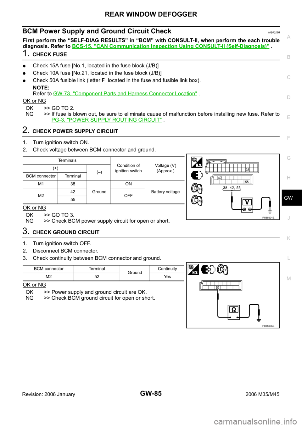
2. CHECK POWER SUPPLY CIRCUIT
1. Turn ignition switch ON.
2. Check voltage between BCM connector and ground.
OK or NG
OK >> GO TO 3.
NG >> Check BCM power supply circuit for open or short.
3. CHECK GROUND CIRCUIT
1. Turn ignition switch OFF.
2. Disconnect BCM connector.
3. Check continuity between BCM connector and ground.
OK or NG
OK >> Power supply and ground circuit are OK.
NG >> Check BCM ground circuit for open or short.
Terminals
Condition of
ignition switchVoltage (V)
(Approx.) (+)
(–)
BCM connector Terminal
M1 38
GroundON
Battery voltage
M242
OFF
55
PIIB5934E
BCM connector Terminal
GroundContinuity
M2 52 Yes
PIIB5935E
Page 3605 of 5621
GW-86
REAR WINDOW DEFOGGER
Revision: 2006 January2006 M35/M45
Rear Window Defogger Switch Circuit CheckNIS0022S
1. CHECK REAR WINDOW DEFOGGER SWITCH OPERATION
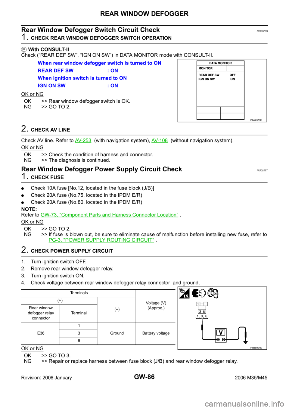
With CONSULT-II
Check (“REAR DEF SW”, “IGN ON SW”) in DATA MONITOR mode with CONSULT-II.
OK or NG
OK >> Rear window defogger switch is OK.
NG >> GO TO 2.
2. CHECK AV LINE
Check AV line. Refer to AV- 2 5 3
(with navigation system), AV- 1 0 8 (without navigation system).
OK or NG
OK >> Check the condition of harness and connector.
NG >> The diagnosis is continued.
Rear Window Defogger Power Supply Circuit CheckNIS0022T
1. CHECK FUSE
Check 10A fuse [No.12, located in the fuse block (J/B)]
Check 20A fuse (No.75, located in the IPDM E/R)
Check 20A fuse (No.80, located in the IPDM E/R)
NOTE:
Refer to GW-73, "
Component Parts and Harness Connector Location" .
OK or NG
OK >> GO TO 2.
NG >> If fuse is blown out, be sure to eliminate cause of malfunction before installing new fuse, refer to
PG-3, "
POWER SUPPLY ROUTING CIRCUIT" .
2. CHECK POWER SUPPLY CIRCUIT
1. Turn ignition switch OFF.
2. Remove rear window defogger relay.
3. Turn ignition switch ON.
4. Check voltage between rear window defogger relay connector and ground.
OK or NG
OK >> GO TO 3.
NG >> Repair or replace harness between fuse block (J/B) and rear window defogger relay. When rear window defogger switch is turned to ON
REAR DEF SW : ON
When ignition switch is turned to ON
IGN ON SW : ON
PIIA2373E
Terminals
Voltage (V)
(Approx.) (+)
(–) Rear window
defogger relay
connectorTerminal
E361
Ground Battery voltage 3
6
PIIB5994E
Page 3606 of 5621
REAR WINDOW DEFOGGER
GW-87
C
D
E
F
G
H
J
K
L
MA
B
GW
Revision: 2006 January2006 M35/M45
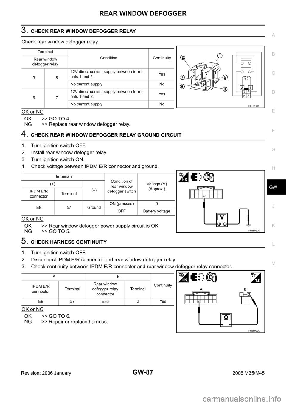
3. CHECK REAR WINDOW DEFOGGER RELAY
Check rear window defogger relay.
OK or NG
OK >> GO TO 4.
NG >> Replace rear window defogger relay.
4. CHECK REAR WINDOW DEFOGGER RELAY GROUND CIRCUIT
1. Turn ignition switch OFF.
2. Install rear window defogger relay.
3. Turn ignition switch ON.
4. Check voltage between IPDM E/R connector and ground.
OK or NG
OK >> Rear window defogger power supply circuit is OK.
NG >> GO TO 5.
5. CHECK HARNESS CONTINUITY
1. Turn ignition switch OFF.
2. Disconnect IPDM E/R connector and rear window defogger relay.
3. Check continuity between IPDM E/R connector and rear window defogger relay connector.
OK or NG
OK >> GO TO 6.
NG >> Repair or replace harness.
Terminal
Condition Continuity
Rear window
defogger relay
3512V direct current supply between termi-
nals 1 and 2.Ye s
No current supply No
6712V direct current supply between termi-
nals 1 and 2.Ye s
No current supply No
SEC202B
Terminals
Condition of
rear window
defogger switchVoltage (V)
(Approx.) (+)
(–)
IPDM E/R
connectorTerminal
E9 57 GroundON (pressed) 0
OFF Battery voltage
PIIB5982E
AB
Continuity
IPDM E/R
connectorTerminalRear window
defogger relay
connectorTerminal
E9 57 E36 2 Yes
PIIB5983E
Page 3607 of 5621
GW-88
REAR WINDOW DEFOGGER
Revision: 2006 January2006 M35/M45
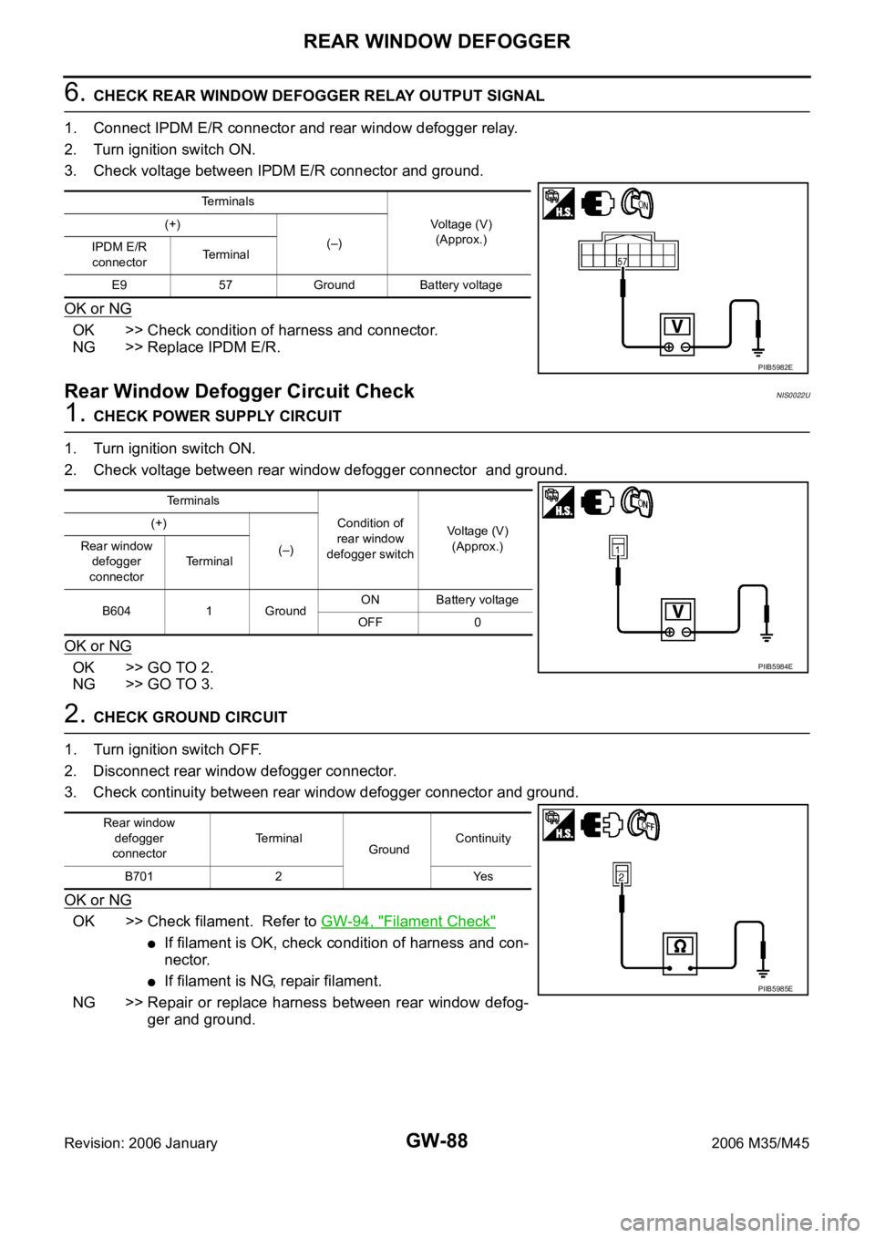
6. CHECK REAR WINDOW DEFOGGER RELAY OUTPUT SIGNAL
1. Connect IPDM E/R connector and rear window defogger relay.
2. Turn ignition switch ON.
3. Check voltage between IPDM E/R connector and ground.
OK or NG
OK >> Check condition of harness and connector.
NG >> Replace IPDM E/R.
Rear Window Defogger Circuit CheckNIS0022U
1. CHECK POWER SUPPLY CIRCUIT
1. Turn ignition switch ON.
2. Check voltage between rear window defogger connector and ground.
OK or NG
OK >> GO TO 2.
NG >> GO TO 3.
2. CHECK GROUND CIRCUIT
1. Turn ignition switch OFF.
2. Disconnect rear window defogger connector.
3. Check continuity between rear window defogger connector and ground.
OK or NG
OK >> Check filament. Refer to GW-94, "Filament Check"
If filament is OK, check condition of harness and con-
nector.
If filament is NG, repair filament.
NG >> Repair or replace harness between rear window defog-
ger and ground.
Terminals
Voltage (V)
(Approx.) (+)
(–)
IPDM E/R
connectorTerminal
E9 57 Ground Battery voltage
PIIB5982E
Te r m i n a l s
Condition of
rear window
defogger switchVoltage (V)
(Approx.) (+)
(–) Rear window
defogger
connectorTerminal
B604 1 GroundON Battery voltage
OFF 0
PIIB5984E
Rear window
defogger
connectorTerminal
GroundContinuity
B701 2 Yes
PIIB5985E
Page 3608 of 5621
REAR WINDOW DEFOGGER
GW-89
C
D
E
F
G
H
J
K
L
MA
B
GW
Revision: 2006 January2006 M35/M45
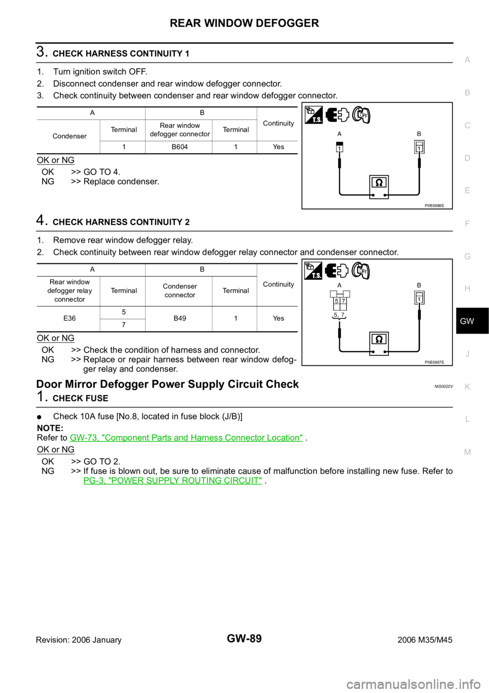
3. CHECK HARNESS CONTINUITY 1
1. Turn ignition switch OFF.
2. Disconnect condenser and rear window defogger connector.
3. Check continuity between condenser and rear window defogger connector.
OK or NG
OK >> GO TO 4.
NG >> Replace condenser.
4. CHECK HARNESS CONTINUITY 2
1. Remove rear window defogger relay.
2. Check continuity between rear window defogger relay connector and condenser connector.
OK or NG
OK >> Check the condition of harness and connector.
NG >> Replace or repair harness between rear window defog-
ger relay and condenser.
Door Mirror Defogger Power Supply Circuit CheckNIS0022V
1. CHECK FUSE
Check 10A fuse [No.8, located in fuse block (J/B)]
NOTE:
Refer to GW-73, "
Component Parts and Harness Connector Location" .
OK or NG
OK >> GO TO 2.
NG >> If fuse is blown out, be sure to eliminate cause of malfunction before installing new fuse. Refer to
PG-3, "
POWER SUPPLY ROUTING CIRCUIT" .
AB
Continuity
CondenserTerminalRear window
defogger connectorTerminal
1B6041Yes
PIIB5986E
AB
Continuity Rear window
defogger relay
connectorTerminalCondenser
connectorTerminal
E365
B49 1 Yes
7
PIIB5987E