2006 INFINITI M35 service
[x] Cancel search: servicePage 1429 of 5621
![INFINITI M35 2006 Factory Service Manual CO-54
[VK45DE]
WATER PUMP
Revision: 2006 January2006 M35/M45
INSPECTION AFTER REMOVAL
Visually check that there is no significant dirt or rusting on water
pump body and vane.
Make sure there is no loo INFINITI M35 2006 Factory Service Manual CO-54
[VK45DE]
WATER PUMP
Revision: 2006 January2006 M35/M45
INSPECTION AFTER REMOVAL
Visually check that there is no significant dirt or rusting on water
pump body and vane.
Make sure there is no loo](/manual-img/42/57023/w960_57023-1428.png)
CO-54
[VK45DE]
WATER PUMP
Revision: 2006 January2006 M35/M45
INSPECTION AFTER REMOVAL
Visually check that there is no significant dirt or rusting on water
pump body and vane.
Make sure there is no looseness in vane shaft, and that it turns
smoothly when rotated by hand.
If anything is found, replace water pump.
INSTALLATION
Installation is the reverse order of removal.
INSPECTION AFTER INSTALLATION
Check for leaks of engine coolant using radiator cap tester adapter [SST: EG17650301 (J–33984-A)] and
radiator cap tester (commercial service tool). Refer to CO-40, "
LEAK CHECK" .
Start and warm up engine. Visually check if there is no leaks of engine coolant.
PBIC1539E
Page 1432 of 5621
![INFINITI M35 2006 Factory Service Manual THERMOSTAT AND WATER CONTROL VALVE
CO-57
[VK45DE]
C
D
E
F
G
H
I
J
K
L
MA
CO
Revision: 2006 January2006 M35/M45
Install thermostat with jiggle valve facing upwards. (The position
deviation may be withi INFINITI M35 2006 Factory Service Manual THERMOSTAT AND WATER CONTROL VALVE
CO-57
[VK45DE]
C
D
E
F
G
H
I
J
K
L
MA
CO
Revision: 2006 January2006 M35/M45
Install thermostat with jiggle valve facing upwards. (The position
deviation may be withi](/manual-img/42/57023/w960_57023-1431.png)
THERMOSTAT AND WATER CONTROL VALVE
CO-57
[VK45DE]
C
D
E
F
G
H
I
J
K
L
MA
CO
Revision: 2006 January2006 M35/M45
Install thermostat with jiggle valve facing upwards. (The position
deviation may be within the range of
10 degrees)
Install water control valve with the up-mark facing up and the
frame center part facing upwards. (The position deviation may
be within the range of
10 degrees)
Water Outlet Pipe and Heater Pipe
First apply a neutral detergent to O-rings, then quickly insert the insertion parts of the water outlet pipe and
heater pipe into the installation holes.
INSPECTION AFTER INSTALLATION
Check for leaks of engine coolant using radiator cap tester adapter [SST: EG17650301 (J33984-A)] and
radiator cap tester (commercial service tool). Refer to CO-40, "
LEAK CHECK" .
Start and warm up engine. Visually check if there is no leaks of engine coolant.
PBIC0158E
Page 1433 of 5621
![INFINITI M35 2006 Factory Service Manual CO-58
[VK45DE]
SERVICE DATA AND SPECIFICATIONS (SDS)
Revision: 2006 January2006 M35/M45
SERVICE DATA AND SPECIFICATIONS (SDS)PFP:00030
Standard and LimitNBS004RT
ENGINE COOLANT CAPACITY (APPROXIMATE)
INFINITI M35 2006 Factory Service Manual CO-58
[VK45DE]
SERVICE DATA AND SPECIFICATIONS (SDS)
Revision: 2006 January2006 M35/M45
SERVICE DATA AND SPECIFICATIONS (SDS)PFP:00030
Standard and LimitNBS004RT
ENGINE COOLANT CAPACITY (APPROXIMATE)](/manual-img/42/57023/w960_57023-1432.png)
CO-58
[VK45DE]
SERVICE DATA AND SPECIFICATIONS (SDS)
Revision: 2006 January2006 M35/M45
SERVICE DATA AND SPECIFICATIONS (SDS)PFP:00030
Standard and LimitNBS004RT
ENGINE COOLANT CAPACITY (APPROXIMATE)
Unit: (US qt, Imp qt)
RADIATOR
Unit: kPa (kg/cm2 , psi)
THERMOSTAT
WATER CONTROL VALVE
Engine coolant capacity (With reservoir tank at “MAX” level) 10.4 (11, 9-1/8)
Reservoir tank engine coolant capacity (at “MAX” level) 0.6 (5/8, 1/2)
Radiator cap relief pressureStandard 78 - 98 (0.8 - 1.0, 11 - 14)
Limit 59 (0.6, 9)
Leakage testing pressure 157 (1.6, 23)
ThermostatStandard
Valve opening temperature 80 - 84
C (176 - 183F)
Maximum valve lift More than 10 mm/ 95
C (0.39 in/ 203F)
Valve closing temperature 77
C (171F)
Water control valveStandard
Valve opening temperature 93.5 - 96.5
C (200 - 206F)
Maximum valve lift More than 8 mm/ 108
C (0.315 in/ 226F)
Valve closing temperature 90
C (194F)
Page 1434 of 5621

DI-1
DRIVER INFORMATION SYSTEM
K ELECTRICAL
CONTENTS
C
D
E
F
G
H
I
J
L
M
SECTION DI
A
B
DI
Revision: 2006 January2006 M35/M45
DRIVER INFORMATION SYSTEM
PRECAUTION ............................................................ 3
Precautions for Supplemental Restraint System
(SRS) “AIR BAG” and “SEAT BELT PRE-TEN-
SIONER” .................................................................. 3
PREPARATION ........................................................... 4
Commercial Service Tools ........................................ 4
COMBINATION METERS ........................................... 5
System Description .................................................. 5
UNIFIED METER CONTROL UNIT ...................... 5
UNIFIED METER AND A/C AMP. ......................... 5
POWER SUPPLY AND GROUND CIRCUIT ........ 5
SPEEDOMETER ................................................... 6
TACHOMETER ..................................................... 6
WATER TEMPERATURE GAUGE ........................ 6
FUEL GAUGE ....................................................... 7
ODO/TRIP METER ............................................... 7
METER ILLUMINATION CONTROL ..................... 8
FAIL-SAFE ............................................................ 9
Arrangement of Combination Meter ....................... 10
Component Parts and Harness Connector Location .... 11
Internal Circuit ........................................................ 12
Wiring Diagram — METER — ................................ 13
Terminals and Reference Value for Combination
Meter ...................................................................... 15
Terminals and Reference Value for Unified Meter
and A/C Amp. ......................................................... 16
Self-Diagnosis Mode of Combination Meter ........... 17
SELF-DIAGNOSIS FUNCTION .......................... 17
OPERATION PROCEDURE ............................... 17
CONSULT-II Function (METER A/C AMP) ............. 18
Trouble Diagnosis .................................................. 18
HOW TO PERFORM TROUBLE DIAGNOSIS ... 18
PRELIMINARY CHECK ...................................... 18
Symptom Chart ...................................................... 18
Power Supply and Ground Circuit Inspection ........ 19
Vehicle Speed Signal Inspection ............................ 20
Engine Speed Signal Inspection ............................ 21
Engine Coolant Temperature Signal Inspection ..... 22
Fuel Level Sensor Signal Inspection ...................... 22
Fuel Gauge Pointer Fluctuates, Indicator Wrong Value or Varies ....................................................... 25
Fuel Gauge Does Not Move to FULL Position ....... 25
Electrical Components Inspection .......................... 26
CHECK FUEL LEVEL SENSOR UNIT ................ 26
Removal and Installation of Combination Meter ..... 27
REMOVAL ........................................................
... 27
INSTALLATION ................................................... 27
Disassembly and Assembly of Combination Meter ... 27
DISASSEMBLY ................................................... 27
ASSEMBLY ......................................................... 27
UNIFIED METER AND A/C AMP ...........................
... 28
System Description ................................................. 28
COMBINATION METER CONTROL FUNCTION ... 28
A/C AUTO AMP. FUNCTION ............................... 29
OTHER FUNCTIONS .......................................... 29
Schematic ............................................................... 30
CONSULT-II Function (METER A/C AMP) ............. 31
CONSULT-II BASIC OPERATION ....................... 31
SELF-DIAG RESULTS ........................................ 32
DATA MONITOR ................................................. 33
Power Supply and Ground Circuit Inspection ......... 35
DTC [U1000] CAN Communication Circuit ............. 36
DTC [B2202] Meter Communication Circuit ........... 36
DTC [B2205] Vehicle Speed Circuit ........................ 39
Removal and Installation of Unified Meter and A/C
Amp. ....................................................................... 39
REMOVAL ........................................................
... 39
INSTALLATION ................................................... 39
WARNING LAMPS .................................................... 40
System Description ................................................. 40
OIL PRESSURE WARNING LAMP ..................... 40
Component Parts and Harness Connector Location ... 41
Schematic ............................................................... 42
Wiring Diagram — WARN — .................................. 43
Oil Pressure Warning Lamp Stays Off (Ignition
Switch ON) ............................................................. 53
Oil Pressure Warning Lamp Does Not Turn Off (Oil
Pressure Is Normal) ................................................ 54
Electrical Component Inspection ............................ 55
OIL PRESSURE SWITCH ................................... 55
Page 1436 of 5621

PRECAUTION
DI-3
C
D
E
F
G
H
I
J
L
MA
B
DI
Revision: 2006 January2006 M35/M45
PRECAUTION PFP:00011
Precautions for Supplemental Restraint System (SRS) “AIR BAG” and “SEAT
BELT PRE-TENSIONER”
NKS003TT
The Supplemental Restraint System such as “AIR BAG” and “SEAT BELT PRE-TENSIONER”, used along
with a front seat belt, helps to reduce the risk or severity of injury to the driver and front passenger for certain
types of collision. This system includes seat belt switch inputs and dual stage front air bag modules. The SRS
system uses the seat belt switches to determine the front air bag deployment, and may only deploy one front
air bag, depending on the severity of a collision and whether the front occupants are belted or unbelted.
Information necessary to service the system safely is included in the SRS and SB section of this Service Man-
ual.
WAR NING :
To avoid rendering the SRS inoperative, which could increase the risk of personal injury or death
in the event of a collision which would result in air bag inflation, all maintenance must be per-
formed by an authorized NISSAN/INFINITI dealer.
Improper maintenance, including incorrect removal and installation of the SRS, can lead to per-
sonal injury caused by unintentional activation of the system. For removal of Spiral Cable and Air
Bag Module, see the SRS section.
Do not use electrical test equipment on any circuit related to the SRS unless instructed to in this
Service Manual. SRS wiring harnesses can be identified by yellow and/or orange harnesses or
harness connectors.
Page 1437 of 5621

DI-4
PREPARATION
Revision: 2006 January2006 M35/M45
PREPARATIONPFP:00002
Commercial Service ToolsNKS003TU
Tool nameDescription
Power toolLoosening bolts, nuts and screws
PIIB1407E
Page 1451 of 5621

DI-18
COMBINATION METERS
Revision: 2006 January2006 M35/M45
CONSULT-II Function (METER A/C AMP)NKS003U3
Refer to DI-31, "CONSULT-II Function (METER A/C AMP)" in “UNIFIED METER AND A/C AMP”.
Trouble DiagnosisNKS003U4
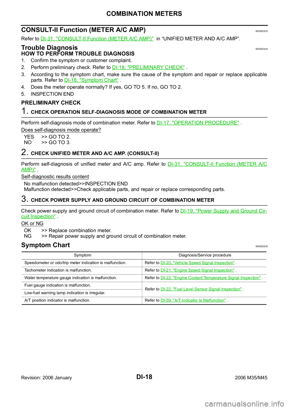
HOW TO PERFORM TROUBLE DIAGNOSIS
1. Confirm the symptom or customer complaint.
2. Perform preliminary check. Refer to DI-18, "
PRELIMINARY CHECK" .
3. According to the symptom chart, make sure the cause of the symptom and repair or replace applicable
parts. Refer to DI-18, "
Symptom Chart" .
4. Does the meter operate normally? If yes, GO TO 5. If no, GO TO 2.
5. INSPECTION END
PRELIMINARY CHECK
1. CHECK OPERATION SELF-DIAGNOSIS MODE OF COMBINATION METER
Perform self-diagnosis mode of combination meter. Refer to DI-17, "
OPERATION PROCEDURE" .
Does self
-diagnosis mode operate?
YES >> GO TO 2.
NO >> GO TO 3.
2. CHECK UNIFIED METER AND A/C AMP. (CONSULT-II)
Perform self-diagnosis of unified meter and A/C amp. Refer to DI-31, "
CONSULT-II Function (METER A/C
AMP)" .
Self
-diagnostic results content
No malfunction detected>>INSPECTION END
Malfunction detected>>Check applicable parts, and repair or replace corresponding parts.
3. CHECK POWER SUPPLY AND GROUND CIRCUIT OF COMBINATION METER
Check power supply and ground circuit of combination meter. Refer to DI-19, "
Power Supply and Ground Cir-
cuit Inspection" .
OK or NG
OK >> Replace combination meter.
NG >> Repair power supply and ground circuit of combination meter.
Symptom ChartNKS003U5
Symptom Diagnosis/Service procedure
Speedometer or odo/trip meter indication is malfunction. Refer to DI-20, "
Vehicle Speed Signal Inspection" .
Tachometer indication is malfunction. Refer to DI-21, "
Engine Speed Signal Inspection" .
Water temperature gauge indication is malfunction. Refer to DI-22, "
Engine Coolant Temperature Signal Inspection" .
Fuel gauge indication is malfunction.
Refer to DI-22, "
Fuel Level Sensor Signal Inspection" .
Low-fuel warning lamp indication is irregular.
A/T position indicator is malfunction. Refer to DI-59, "
A/T Indicator Is Malfunction" .
Page 1505 of 5621

DI-72
WARNING CHIME
Revision: 2006 January2006 M35/M45
2. CHECK UNIFIED METER AND A/C AMP. (CONSULT-II)
Perform self-diagnosis of unified meter and A/C amp. Refer to DI-71, "
CONSULT-II Function (METER A/C
AMP)" .
Self
-diagnostic results content
No malfunction detected>> INSPECTION END
Malfunction detected>> Check applicable parts, and repair or replace corresponding parts.
SYMPTOM CHART
Meter Buzzer Circuit InspectionNKS003V8
1. CHECK OPERATION OF METER BUZZER
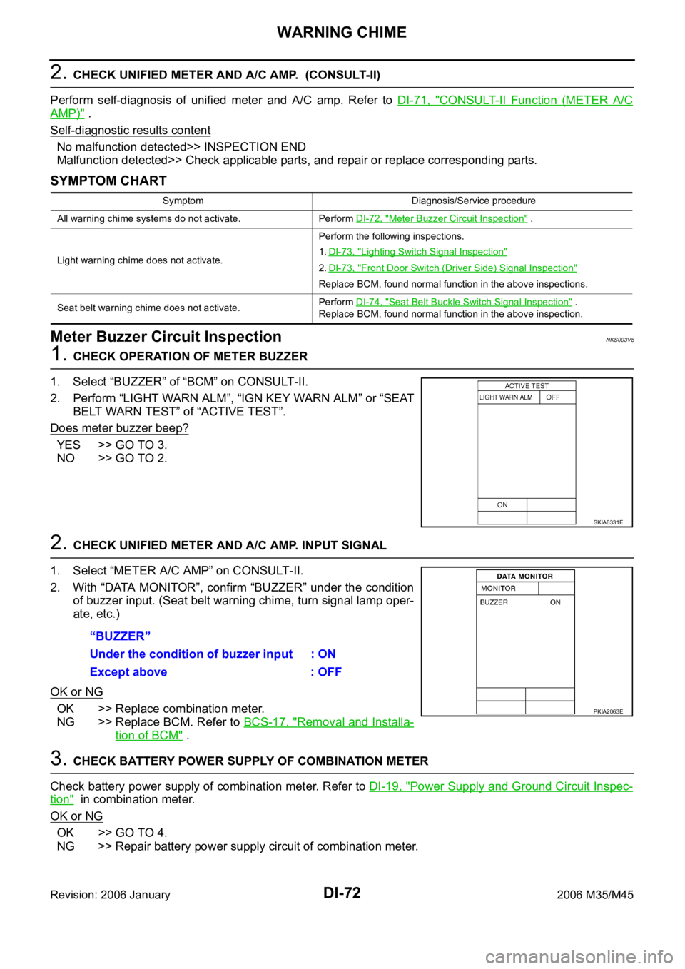
1. Select “BUZZER” of “BCM” on CONSULT-II.
2. Perform “LIGHT WARN ALM”, “IGN KEY WARN ALM” or “SEAT
BELT WARN TEST” of “ACTIVE TEST”.
Does meter buzzer beep?
YES >> GO TO 3.
NO >> GO TO 2.
2. CHECK UNIFIED METER AND A/C AMP. INPUT SIGNAL
1. Select “METER A/C AMP” on CONSULT-II.
2. With “DATA MONITOR”, confirm “BUZZER” under the condition
of buzzer input. (Seat belt warning chime, turn signal lamp oper-
ate, etc.)
OK or NG
OK >> Replace combination meter.
NG >> Replace BCM. Refer to BCS-17, "
Removal and Installa-
tion of BCM" .
3. CHECK BATTERY POWER SUPPLY OF COMBINATION METER
Check battery power supply of combination meter. Refer to DI-19, "
Power Supply and Ground Circuit Inspec-
tion" in combination meter.
OK or NG
OK >> GO TO 4.
NG >> Repair battery power supply circuit of combination meter.
Symptom Diagnosis/Service procedure
All warning chime systems do not activate. Perform DI-72, "
Meter Buzzer Circuit Inspection" .
Light warning chime does not activate.Perform the following inspections.
1.DI-73, "
Lighting Switch Signal Inspection"
2.DI-73, "Front Door Switch (Driver Side) Signal Inspection"
Replace BCM, found normal function in the above inspections.
Seat belt warning chime does not activate.Perform DI-74, "
Seat Belt Buckle Switch Signal Inspection" .
Replace BCM, found normal function in the above inspection.
SKIA6331E
“BUZZER”
Under the condition of buzzer input : ON
Except above : OFF
PKIA2063E