Page 4498 of 5621

HEADLAMP (FOR USA) - XENON TYPE -
LT-71
C
D
E
F
G
H
I
J
L
MA
B
LT
Revision: 2006 January2006 M35/M45
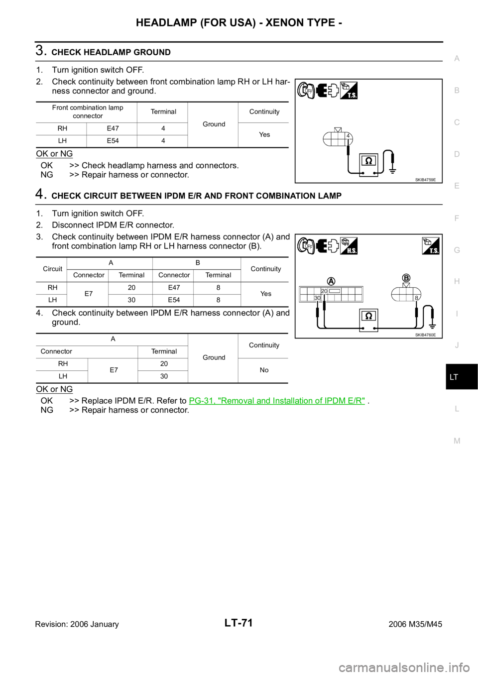
3. CHECK HEADLAMP GROUND
1. Turn ignition switch OFF.
2. Check continuity between front combination lamp RH or LH har-
ness connector and ground.
OK or NG
OK >> Check headlamp harness and connectors.
NG >> Repair harness or connector.
4. CHECK CIRCUIT BETWEEN IPDM E/R AND FRONT COMBINATION LAMP
1. Turn ignition switch OFF.
2. Disconnect IPDM E/R connector.
3. Check continuity between IPDM E/R harness connector (A) and
front combination lamp RH or LH harness connector (B).
4. Check continuity between IPDM E/R harness connector (A) and
ground.
OK or NG
OK >> Replace IPDM E/R. Refer to PG-31, "Removal and Installation of IPDM E/R" .
NG >> Repair harness or connector.
Front combination lamp
connectorTe r m i n a l
GroundContinuity
RH E47 4
Ye s
LH E54 4
SKIB4759E
CircuitAB
Continuity
Connector Terminal Connector Terminal
RH
E720 E47 8
Ye s
LH 30 E54 8
A
GroundContinuity
Connector Terminal
RH
E720
No
LH 30
SKIB4760E
Page 4504 of 5621

HEADLAMP (FOR USA) - XENON TYPE -
LT-77
C
D
E
F
G
H
I
J
L
MA
B
LT
Revision: 2006 January2006 M35/M45
Disassembly and Assembly NKS003P8
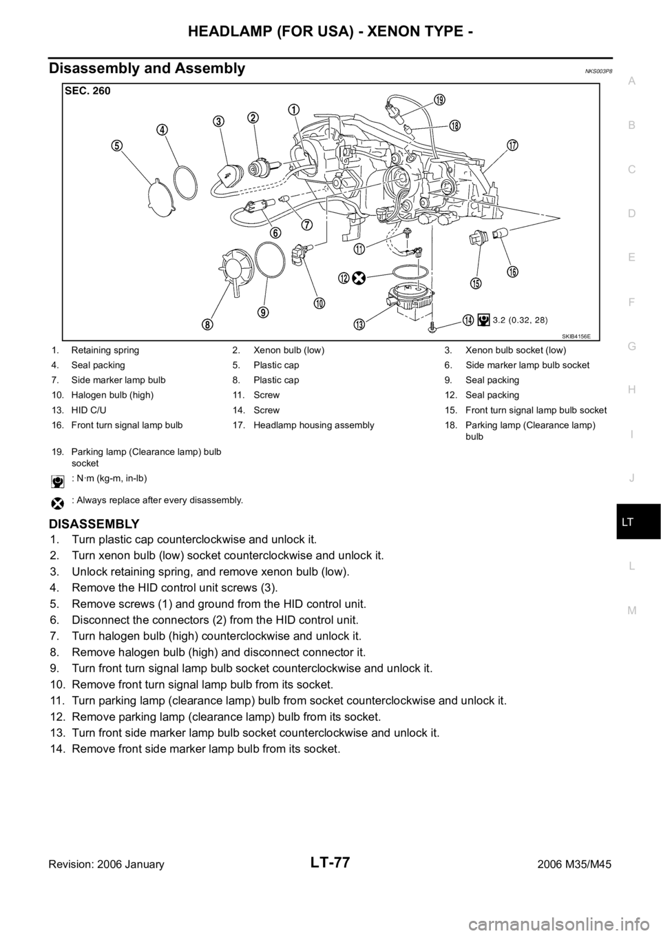
DISASSEMBLY
1. Turn plastic cap counterclockwise and unlock it.
2. Turn xenon bulb (low) socket counterclockwise and unlock it.
3. Unlock retaining spring, and remove xenon bulb (low).
4. Remove the HID control unit screws (3).
5. Remove screws (1) and ground from the HID control unit.
6. Disconnect the connectors (2) from the HID control unit.
7. Turn halogen bulb (high) counterclockwise and unlock it.
8. Remove halogen bulb (high) and disconnect connector it.
9. Turn front turn signal lamp bulb socket counterclockwise and unlock it.
10. Remove front turn signal lamp bulb from its socket.
11. Turn parking lamp (clearance lamp) bulb from socket counterclockwise and unlock it.
12. Remove parking lamp (clearance lamp) bulb from its socket.
13. Turn front side marker lamp bulb socket counterclockwise and unlock it.
14. Remove front side marker lamp bulb from its socket.
SKIB4156E
1. Retaining spring 2. Xenon bulb (low) 3. Xenon bulb socket (low)
4. Seal packing 5. Plastic cap 6. Side marker lamp bulb socket
7. Side marker lamp bulb 8. Plastic cap 9. Seal packing
10. Halogen bulb (high) 11. Screw 12. Seal packing
13. HID C/U 14. Screw 15. Front turn signal lamp bulb socket
16. Front turn signal lamp bulb 17. Headlamp housing assembly 18. Parking lamp (Clearance lamp)
bulb
19. Parking lamp (Clearance lamp) bulb
socket
: Nꞏm (kg-m, in-lb)
: Always replace after every disassembly.
Page 4507 of 5621

LT-80
HEADLAMP (FOR CANADA) - DAYTIME LIGHT SYSTEM -
Revision: 2006 January2006 M35/M45
OUTLINE
Power is supplied at all times
to headlamp high relay, located in IPDM E/R (intelligent power distribution module engine room) and
to headlamp low relay, located in IPDM E/R, from battery direct,
through 15A fuse (No. 71, located in IPDM E/R)
to CPU (central processing unit), located in IPDM E/R,
through 15A fuse (No. 78, located in IPDM E/R)
to CPU, located in IPDM E/R,
through 50A fusible link (letter F, located in fuse and fusible link block)
to BCM terminal 55,
through 10A fuse [No. 21, located in fuse block (J/B)]
to BCM terminal 42 and
to combination meter terminal 23,
through 10A fuse (No. 32, located in IPDM E/R)
to daytime light relay terminals 2 and 5,
through 10A fuse [No. 19, located in fuse block (J/B)]
to unified meter and A/C amp. terminal 54,
through 10A fuse [No. 22, located in fuse block (J/B)]
to key slot terminal 1.
When the ignition switch is in ON or START position, power is supplied
to CPU, located in IPDM E/R,
through 15A fuse [No. 1, located in fuse block (J/B)]
to BCM terminal 38,
through 10A fuse [No. 14, located in fuse block (J/B)]
to combination meter terminal 12,
through 10A fuse [No. 12, located in fuse block (J/B)]
to unified meter and A/C amp. terminal 53.
Ground is supplied
to BCM terminal 52
to combination meter terminals 9, 10, and 11
to unified meter and A/C amp. terminal 55 and 71
to push-button ignition switch (push switch) terminal 1
to key slot terminal 8
through grounds M16 and M70,
to IPDM E/R terminals 38 and 51
through grounds E22 and E43.
Page 4508 of 5621

HEADLAMP (FOR CANADA) - DAYTIME LIGHT SYSTEM -
LT-81
C
D
E
F
G
H
I
J
L
MA
B
LT
Revision: 2006 January2006 M35/M45
HEADLAMP OPERATION
Low Beam Operation
With the lighting switch in 2ND position, the BCM receives input signal requesting the headlamps to illuminate.
This input signal is communicated to IPDM E/R across the CAN communication lines. The CPU located in the
IPDM E/R controls the headlamp low relay coil, which when energized, directs power
through 15A fuse (No. 76, located in IPDM E/R)
through IPDM E/R terminal 20
to front combination lamp RH terminal 8,
through 15A fuse (No. 86, located in IPDM E/R)
through IPDM E/R terminal 30
to front combination lamp LH terminal 8.
Ground is supplied
to front combination lamp RH terminal 4
to front combination lamp LH terminal 4
through grounds E22 and E43.
With power and ground supplied, low beam headlamps illuminate.
High Beam Operation (When Daytime Light Does Not Operate)/Flash-to-Pass Operation
With the lighting switch in 2ND position and placed in HIGH BEAM or PASSING position, the BCM receives
input signal requesting headlamp high beams to illuminate. High beam request signal is communicated to the
IPDM E/R across the CAN communication lines. The CPU located in the IPDM E/R controls headlamp high
relay coil and low relay coil, which when energized, directs power
through 10A fuse (No. 72, located in IPDM E/R)
through IPDM E/R terminal 27
through front combination lamp RH terminals 6 and 2
to daytime light relay terminal 3,
through 10A fuse (No. 74, located in IPDM E/R)
through IPDM E/R terminal 28
to front combination lamp LH terminal 6,
through 15A fuse (No. 76, located in IPDM E/R)
through IPDM E/R terminal 20
to front combination lamp RH terminal 8,
through 15A fuse (No. 86, located in IPDM E/R)
through IPDM E/R terminal 30
to front combination lamp LH terminal 8.
Ground is supplied
to daytime light relay terminal 4
to front combination lamp RH terminal 4
to front combination lamp LH terminal 2
to front combination lamp LH terminal 4
through grounds E22 and E43.
With the power and ground supplied, the headlamp high beam and low headlamp illuminate.
High beam indicator illuminates when combination meter receives input signal requesting high beam indicator
to illuminate. This is communicated to BCM across the CAN communication lines.
Page 4509 of 5621

LT-82
HEADLAMP (FOR CANADA) - DAYTIME LIGHT SYSTEM -
Revision: 2006 January2006 M35/M45
DAYTIME LIGHT OPERATION
With the engine running, the lighting switch in the OFF or AUTO position (headlamp is not illuminate) and
parking brake released, the IPDM E/R receives input request signal from BCM to turn on daytime light. This
input is communicated across the CAN communication lines. The CPU of the IPDM E/R controls the daytime
light relay coil. When energized, this relay directs power
through daytime light relay terminals 5 and 3
through front combination lamp RH terminal 2
through front combination lamp RH terminal 6
through IPDM E/R terminal 27
through 10A fuse (No. 72, located in IPDM E/R)
through 10A fuse (No. 74, located in IPDM E/R)
through IPDM E/R terminal 28
to front combination lamp LH terminal 6.
Ground is supplied
to combination lamp LH terminal 2
through grounds E22 and E43.
With power and grounds supplied, the daytime lights illuminate. The high beam headlamps are now wired in
series and illuminate at a reduced intensity.
COMBINATION SWITCH READING FUNCTION
Refer to BCS-3, "COMBINATION SWITCH READING FUNCTION" .
AUTO LIGHT OPERATION
For auto light operation, refer to LT- 11 6 , "System Description" .
CAN Communication System DescriptionNKS003PB
Refer to LAN-34, "CAN COMMUNICATION" .
Page 4517 of 5621
LT-90
HEADLAMP (FOR CANADA) - DAYTIME LIGHT SYSTEM -
Revision: 2006 January2006 M35/M45
35 SBCombination
switch output 2ONLighting, turn, wiper
switch
(Wiper dial position 4)
Any of several con-
ditions below
Lighting switch 2ND
Lighting switch
PASSING (Operates
only PASSING switch)
Approx. 1.2V
OFF
Approx. 7.0 - 7.5V
38 WIgnition switch
(ON) ON — Battery voltage
39 L CAN
H — — —
40 P CAN
L — — —
42 PBattery power
supplyOFF — Battery voltage
52 B Ground ON — Approx. 0V
55 WBattery power
supplyOFF — Battery voltage Terminal
No.Wire
colorSignal nameMeasuring condition
Reference value
Ignition
switchOperation or condition
PKIB4958J
PKIB4960J
Page 4518 of 5621

HEADLAMP (FOR CANADA) - DAYTIME LIGHT SYSTEM -
LT-91
C
D
E
F
G
H
I
J
L
MA
B
LT
Revision: 2006 January2006 M35/M45
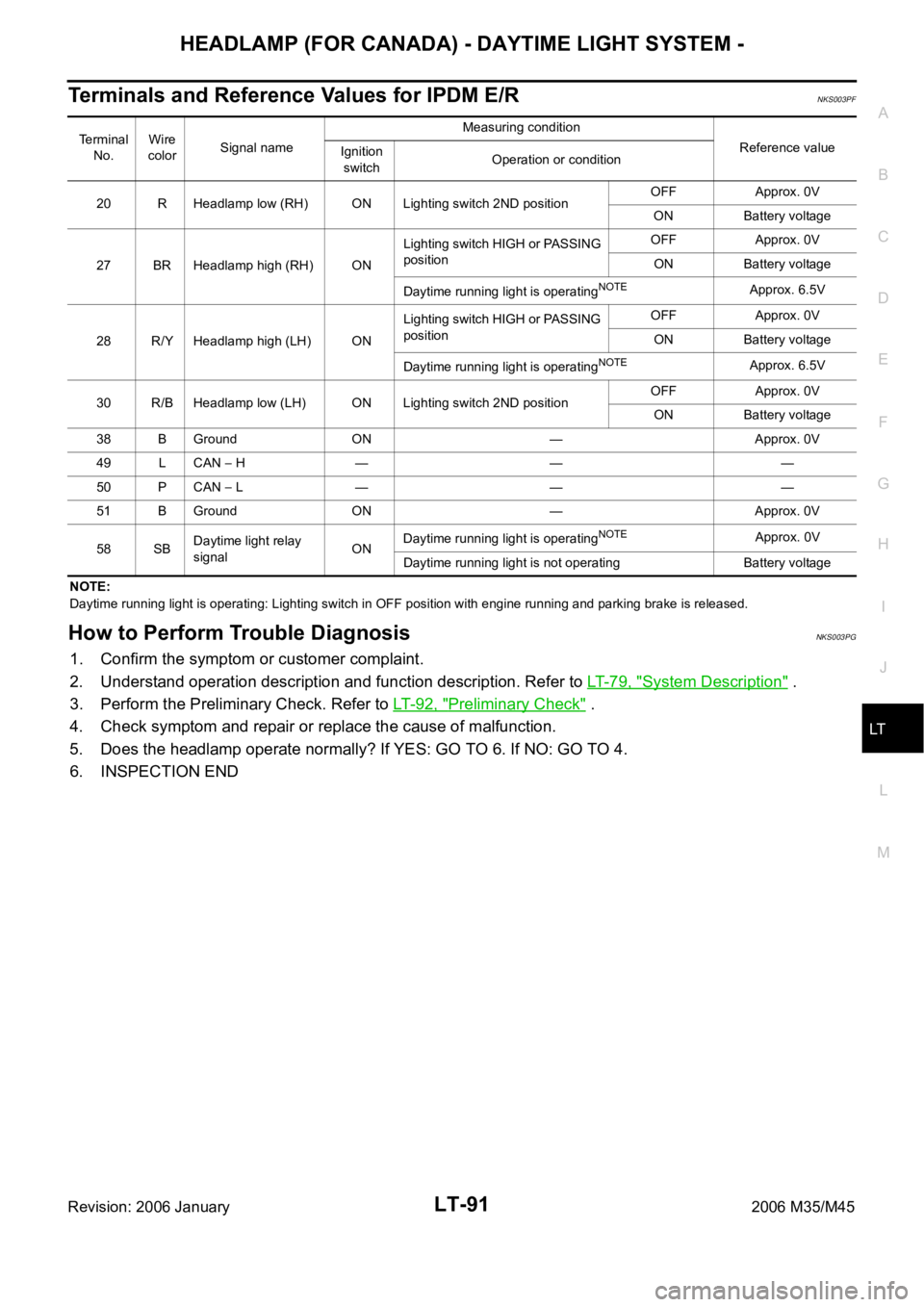
Terminals and Reference Values for IPDM E/RNKS003PF
NOTE:
Daytime running light is operating: Lighting switch in OFF position with engine running and parking brake is released.
How to Perform Trouble DiagnosisNKS003PG
1. Confirm the symptom or customer complaint.
2. Understand operation description and function description. Refer to LT- 7 9 , "
System Description" .
3. Perform the Preliminary Check. Refer to LT-92, "
Preliminary Check" .
4. Check symptom and repair or replace the cause of malfunction.
5. Does the headlamp operate normally? If YES: GO TO 6. If NO: GO TO 4.
6. INSPECTION END
Terminal
No.Wire
colorSignal nameMeasuring condition
Reference value
Ignition
switchOperation or condition
20 R Headlamp low (RH) ON Lighting switch 2ND positionOFF Approx. 0V
ON Battery voltage
27 BR Headlamp high (RH) ONLighting switch HIGH or PASSING
positionOFF Approx. 0V
ON Battery voltage
Daytime running light is operating
NOTEApprox. 6.5V
28 R/Y Headlamp high (LH) ONLighting switch HIGH or PASSING
positionOFF Approx. 0V
ON Battery voltage
Daytime running light is operating
NOTEApprox. 6.5V
30 R/B Headlamp low (LH) ON Lighting switch 2ND positionOFF Approx. 0V
ON Battery voltage
38 B Ground ON — Approx. 0V
49 L CAN
H — — —
50 P CAN
L — — —
51 B Ground ON — Approx. 0V
58 SBDaytime light relay
signalONDaytime running light is operating
NOTEApprox. 0V
Daytime running light is not operating Battery voltage
Page 4519 of 5621

LT-92
HEADLAMP (FOR CANADA) - DAYTIME LIGHT SYSTEM -
Revision: 2006 January2006 M35/M45
Preliminary CheckNKS003PH
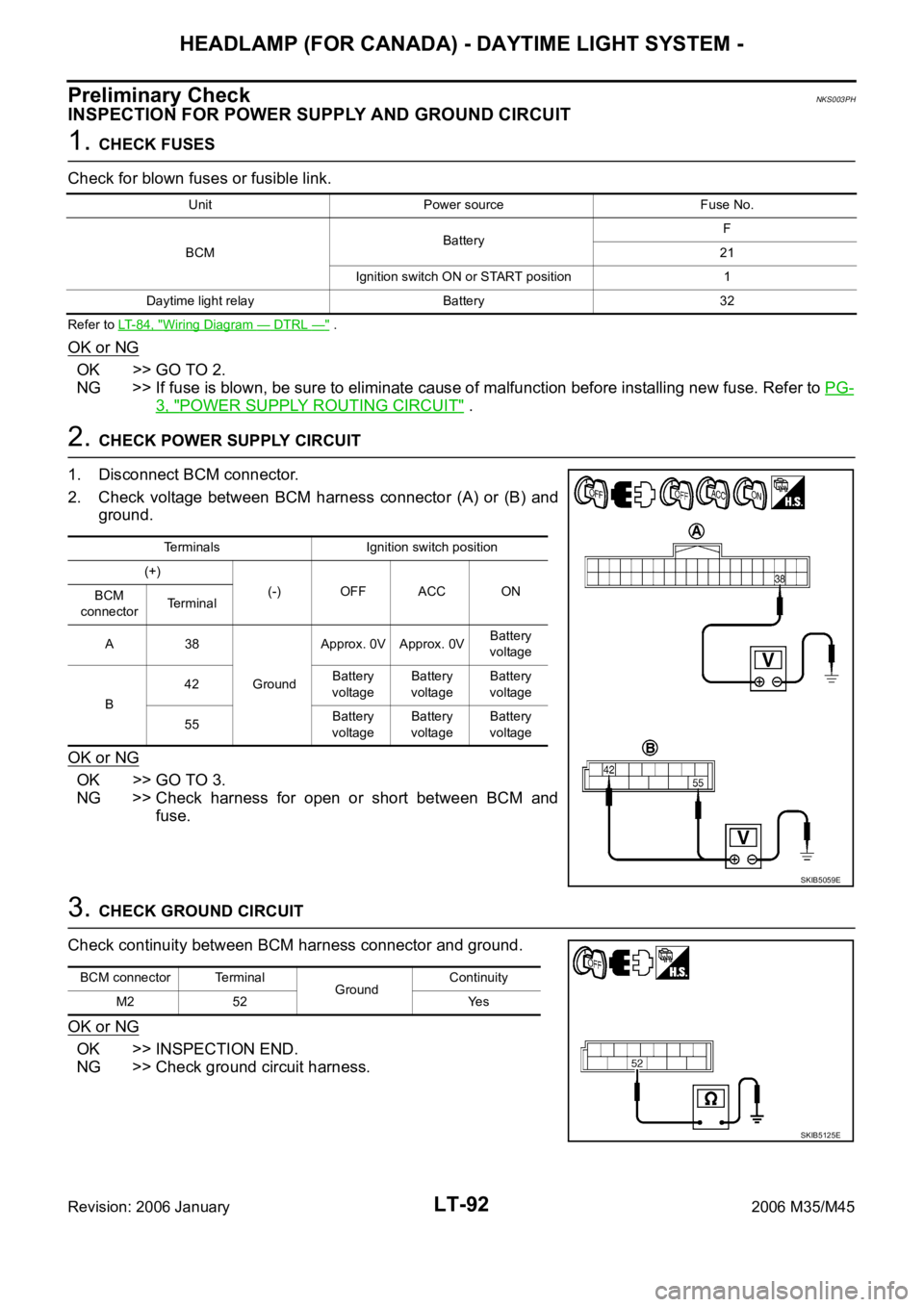
INSPECTION FOR POWER SUPPLY AND GROUND CIRCUIT
1. CHECK FUSES
Check for blown fuses or fusible link.
Refer to LT-84, "Wiring Diagram — DTRL —" .
OK or NG
OK >> GO TO 2.
NG >> If fuse is blown, be sure to eliminate cause of malfunction before installing new fuse. Refer to PG-
3, "POWER SUPPLY ROUTING CIRCUIT" .
2. CHECK POWER SUPPLY CIRCUIT
1. Disconnect BCM connector.
2. Check voltage between BCM harness connector (A) or (B) and
ground.
OK or NG
OK >> GO TO 3.
NG >> Check harness for open or short between BCM and
fuse.
3. CHECK GROUND CIRCUIT
Check continuity between BCM harness connector and ground.
OK or NG
OK >> INSPECTION END.
NG >> Check ground circuit harness.
Unit Power source Fuse No.
BCMBatteryF
21
Ignition switch ON or START position 1
Daytime light relay Battery 32
Terminals Ignition switch position
(+)
(-) OFF ACC ON
BCM
connectorTerminal
A38
GroundApprox. 0V Approx. 0VBattery
voltage
B42Battery
voltageBattery
voltageBattery
voltage
55Battery
voltageBattery
voltageBattery
voltage
SKIB5059E
BCM connector Terminal
GroundContinuity
M2 52 Yes
SKIB5125E