Page 4669 of 5621

LT-242
COMBINATION SWITCH
Revision: 2006 January2006 M35/M45
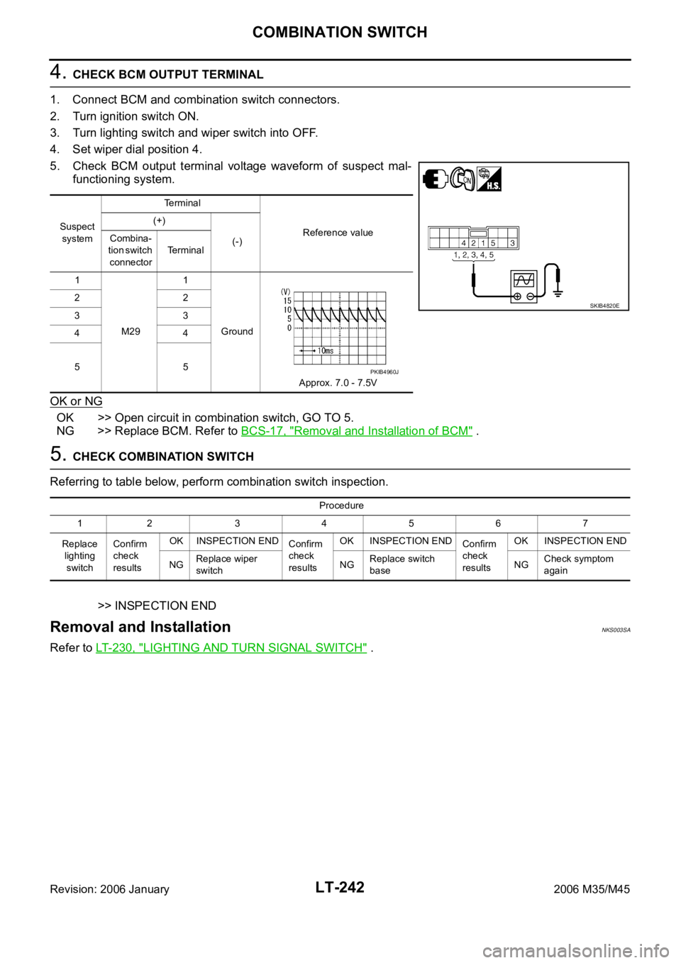
4. CHECK BCM OUTPUT TERMINAL
1. Connect BCM and combination switch connectors.
2. Turn ignition switch ON.
3. Turn lighting switch and wiper switch into OFF.
4. Set wiper dial position 4.
5. Check BCM output terminal voltage waveform of suspect mal-
functioning system.
OK or NG
OK >> Open circuit in combination switch, GO TO 5.
NG >> Replace BCM. Refer to BCS-17, "
Removal and Installation of BCM" .
5. CHECK COMBINATION SWITCH
Referring to table below, perform combination switch inspection.
>> INSPECTION END
Removal and InstallationNKS003SA
Refer to LT- 2 3 0 , "LIGHTING AND TURN SIGNAL SWITCH" .
Suspect
systemTerminal
Reference value (+)
(-) Combina-
tion switch
connectorTerminal
1
M291
Ground
Approx. 7.0 - 7.5V 22
33
44
55
SKIB4820E
PKIB4960J
Procedure
12 34567
Replace
lighting
switchConfirm
check
resultsOK INSPECTION END
Confirm
check
resultsOK INSPECTION END
Confirm
check
resultsOK INSPECTION END
NGReplace wiper
switchNGReplace switch
baseNGCheck symptom
again
Page 4672 of 5621
STOP LAMP
LT-245
C
D
E
F
G
H
I
J
L
MA
B
LT
Revision: 2006 January2006 M35/M45
High-Mounted Stop Lamp NKS003SC
BULB REPLACEMENT, REMOVAL AND INSTALLATION
1. Remove rear parcel shelf finisher. Refer to EI-42, "REAR PARCEL SHELF FINISHER" .
2. Turned over protection sheet and disconnect connector.
3. Remove screws (A) and remove high-mounted stop lamp (1)
from rear parcel shelf finisher.
Stop LampNKS003SD
BULB REPLACEMENT
Refer to LT-266, "Bulb Replacement" .
BULB REPLACEMENT
Refer to LT-266, "Removal and Installation" . High-mounted stop lamp : LED
SKIB4187E
Page 4675 of 5621
LT-248
BACK-UP LAMP
Revision: 2006 January2006 M35/M45
Removal and InstallationNKS003SG
REMOVAL
1. Remove trunk lid finisher inner. Refer to EI-33, "TRUNK LID FINISHER" .
2. Disconnect back up lamp and trunk lid request switch connector.
3. Remove trunk lid finisher outer. Refer to EI-33, "
TRUNK LID FINISHER" .
4. Remove screws (2) and clip, and then remove back up lamp.
5. Remove seal packing from back up lamp.
INSTALLATION
Installation is the reverse order of removal.
Install a new seal packing to the back up lamp.
CAUTION:
Seal packing cannot be reused.
1. Nut 2. Nut 3. Seal packing
4. Clip 5. Back up lamp 6. Two-sided tape
7. Trunk lid finisher outer 8. Screw
: Nꞏm (kg-m, in-lb)
: Always replace after every disassembly.
SKIB4190E
Back up lamp mounting nut : 3.0 Nꞏm (0.31 kg-m, 27 in-lb)
Trunk lid finisher mounting nut : 3.0 Nꞏm (0.31 kg-m, 27 in-lb)
Page 4685 of 5621

LT-258
PARKING, LICENSE PLATE AND TAIL LAMPS
Revision: 2006 January2006 M35/M45
Terminals and Reference Values for IPDM E/RNKS003SO
How to Perform Trouble DiagnosesNKS003SP
1. Confirm the symptom or customer complaint.
2. Understand operation description and function description. Refer to LT- 2 4 9 , "
System Description" .
3. Carry out the Preliminary Check. Refer to LT- 2 5 8 , "
Preliminary Check" .
4. Check symptom and repair or replace the cause of malfunction.
5. Do the parking, license plate and tail lamps operate normally? If YES, GO TO 6. If NO, GO TO 4.
6. INSPECTION END
Preliminary CheckNKS003SQ
CHECK POWER SUPPLY AND GROUND CIRCUIT
1. CHECK FUSE
Check for blown fuses.
Refer to LT-252, "Wiring Diagram — TAIL/L —" .
OK or NG
OK >> GO TO 2.
NG >> If fuse or fusible link is blown, be sure to eliminate cause of malfunction before installing new fuse
or fusible link. Refer to PG-3, "
POWER SUPPLY ROUTING CIRCUIT" .
Terminal
No.Wire
colorSignal nameMeasuring condition
Reference value
Ignition
switchOperation or condition
21 R/LParking, license plate, and
tail lamp outputONLighting switch
1STOFF Approx. 0V
ON Battery voltage
38 B Ground ON — Approx. 0V
49 L CAN
H — — —
50 P CAN
L — — —
51 B Ground ON — Approx. 0V
Unit Power source Fuse and fusible link No.
BCMBatteryF
21
Ignition switch ON or START position 1
Ignition switch ACC or ON position 6
IPDM E/R Battery71
78
Page 4687 of 5621

LT-260
PARKING, LICENSE PLATE AND TAIL LAMPS
Revision: 2006 January2006 M35/M45
Parking, License Plate and Tail Lamps Do Not IlluminateNKS003ST
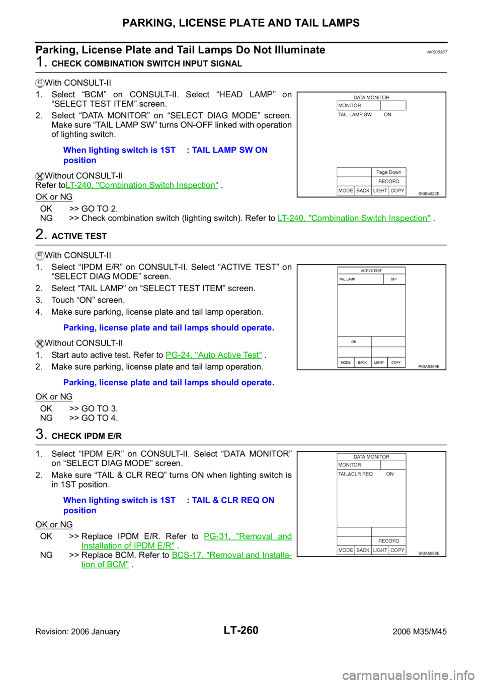
1. CHECK COMBINATION SWITCH INPUT SIGNAL
With CONSULT-II
1. Select “BCM” on CONSULT-II. Select “HEAD LAMP” on
“SELECT TEST ITEM” screen.
2. Select “DATA MONITOR” on “SELECT DIAG MODE” screen.
Make sure “TAIL LAMP SW” turns ON-OFF linked with operation
of lighting switch.
Without CONSULT-II
Refer toLT-240, "
Combination Switch Inspection" .
OK or NG
OK >> GO TO 2.
NG >> Check combination switch (lighting switch). Refer to LT-240, "
Combination Switch Inspection" .
2. ACTIVE TEST
With CONSULT-II
1. Select “IPDM E/R” on CONSULT-II. Select “ACTIVE TEST” on
“SELECT DIAG MODE” screen.
2. Select “TAIL LAMP” on “SELECT TEST ITEM” screen.
3. Touch “ON” screen.
4. Make sure parking, license plate and tail lamp operation.
Without CONSULT-II
1. Start auto active test. Refer to PG-24, "
Auto Active Test" .
2. Make sure parking, license plate and tail lamp operation.
OK or NG
OK >> GO TO 3.
NG >> GO TO 4.
3. CHECK IPDM E/R
1. Select “IPDM E/R” on CONSULT-II. Select “DATA MONITOR”
on “SELECT DIAG MODE” screen.
2. Make sure “TAIL & CLR REQ” turns ON when lighting switch is
in 1ST position.
OK or NG
OK >> Replace IPDM E/R. Refer to PG-31, "Removal and
Installation of IPDM E/R" .
NG >> Replace BCM. Refer to BCS-17, "
Removal and Installa-
tion of BCM" . When lighting switch is 1ST
position: TAIL LAMP SW ON
SKIB4822E
Parking, license plate and tail lamps should operate.
Parking, license plate and tail lamps should operate.
PKIA6359E
When lighting switch is 1ST
position: TAIL & CLR REQ ON
SKIA5958E
Page 4690 of 5621

PARKING, LICENSE PLATE AND TAIL LAMPS
LT-263
C
D
E
F
G
H
I
J
L
MA
B
LT
Revision: 2006 January2006 M35/M45
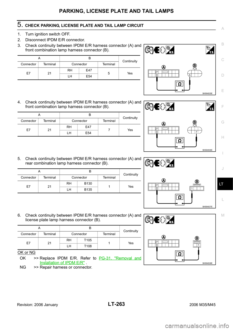
5. CHECK PARKING, LICENSE PLATE AND TAIL LAMP CIRCUIT
1. Turn ignition switch OFF.
2. Disconnect IPDM E/R connector.
3. Check continuity between IPDM E/R harness connector (A) and
front combination lamp harness connector (B).
4. Check continuity between IPDM E/R harness connector (A) and
front combination lamp harness connector (B).
5. Check continuity between IPDM E/R harness connector (A) and
rear combination lamp harness connector (B).
6. Check continuity between IPDM E/R harness connector (A) and
license plate lamp harness connector (B).
OK or NG
OK >> Replace IPDM E/R. Refer to PG-31, "Removal and
Installation of IPDM E/R" .
NG >> Repair harness or connector.
AB
Continuity
Connector Terminal Connector Terminal
E7 21RH E47
5Yes
LH E54
SKIB4835E
AB
Continuity
Connector Terminal Connector Terminal
E7 21RH E47
7Yes
LH E54
SKIB4836E
AB
Continuity
Connector Terminal Connector Terminal
E7 21RH B130
1Yes
LH B135
SKIB4837E
AB
Continuity
Connector Terminal Connector Terminal
E7 21RH T105
1Yes
LH T108
SKIB4838E
Page 4692 of 5621

PARKING, LICENSE PLATE AND TAIL LAMPS
LT-265
C
D
E
F
G
H
I
J
L
MA
B
LT
Revision: 2006 January2006 M35/M45
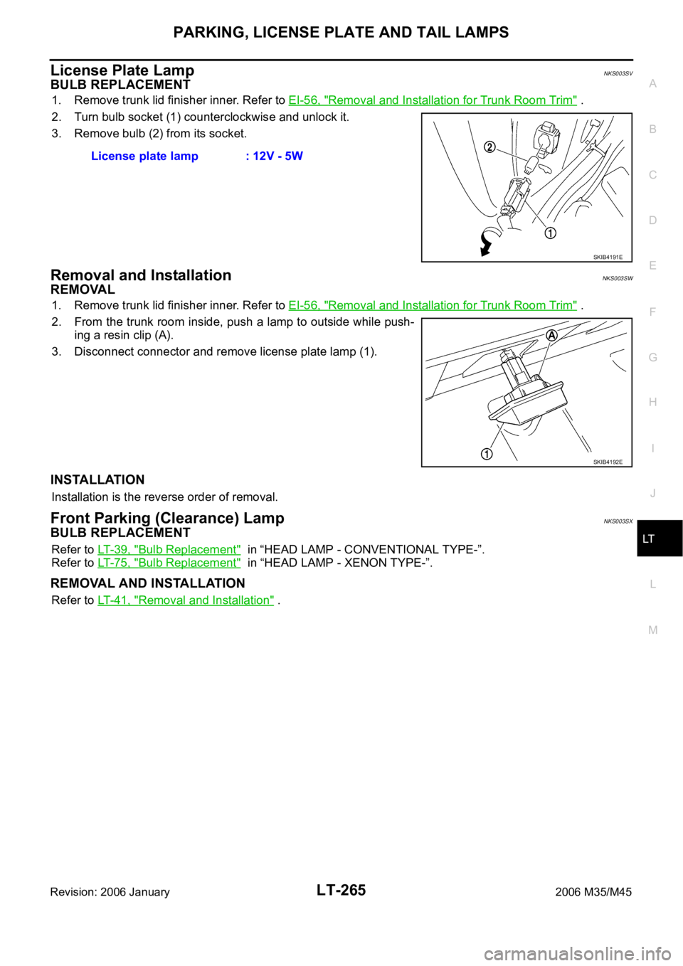
License Plate LampNKS003SV
BULB REPLACEMENT
1. Remove trunk lid finisher inner. Refer to EI-56, "Removal and Installation for Trunk Room Trim" .
2. Turn bulb socket (1) counterclockwise and unlock it.
3. Remove bulb (2) from its socket.
Removal and InstallationNKS003SW
REMOVAL
1. Remove trunk lid finisher inner. Refer to EI-56, "Removal and Installation for Trunk Room Trim" .
2. From the trunk room inside, push a lamp to outside while push-
ing a resin clip (A).
3. Disconnect connector and remove license plate lamp (1).
INSTALLATION
Installation is the reverse order of removal.
Front Parking (Clearance) LampNKS003SX
BULB REPLACEMENT
Refer to LT- 3 9 , "Bulb Replacement" in “HEAD LAMP - CONVENTIONAL TYPE-”.
Refer to LT- 7 5 , "
Bulb Replacement" in “HEAD LAMP - XENON TYPE-”.
REMOVAL AND INSTALLATION
Refer to LT- 4 1 , "Removal and Installation" . License plate lamp : 12V - 5W
SKIB4191E
SKIB4192E
Page 4693 of 5621

LT-266
REAR COMBINATION LAMP
Revision: 2006 January2006 M35/M45
REAR COMBINATION LAMPPFP:26554
Bulb ReplacementNKS003SY
REAR TURN SIGNAL LAMP BULB, STOP/TAIL LAMP BULB
1. Remove trunk side finisher. Refer to EI-56, "Removal and Installation for Trunk Room Trim" .
2. Turn rear turn signal lamp bulb socket (1) counterclockwise and
unlock it.
3. Remove bulb (2).
Removal and InstallationNKS003SZ
REMOVAL
Rear Fender Side
1. Remove trunk side finisher. Refer to EI-56, "Removal and Installation for Trunk Room Trim" .
2. Disconnect rear combination lamp connector.
3. Remove rear combination lamp mounting nuts (A).
4. Pull the rear combination lamp (2) toward rear of the vehicle and
remove from the vehicle.
5. Remove seal packing (1) from the vehicle.
INSTALLATION
Installation is the reverse order of removal.
CAUTION:
Seal packing cannot be reused.Rear turn signal lamp : 12V - 21W (amber bulb)
Stop tail lamp : LED
SKIB4193E
: Nꞏm (kg-m, in-lb)
: Always replace after every disassembly
SKIB4194E