2006 INFINITI M35 ECU
[x] Cancel search: ECUPage 1086 of 5621

INTELLIGENT KEY SYSTEM/ENGINE START FUNCTION
BL-147
C
D
E
F
G
H
J
K
L
MA
B
BL
Revision: 2006 January2006 M35/M45
Terminals and Reference Value for BCMNIS001YG
Terminals and Reference Value for IPDM E/RNIS001YH
6 B Ground — — 0
7 LG Power source LOCK — Battery voltage
8 L/Y Condition signal-2LOCK Steering lock: Lock Battery voltage
ACC
Steering lock: Unlock0
ON 0 Termi-
nal
No.Wire
colorItemCondition
Voltage (V)
(Approx.) Push-
button
ignition
switch
positionOperation or conditions
Te r m i -
nal
No.Wire
colorItemCondition
Voltage (V)
(Approx.) Push-but-
ton igni-
tion
switch
positionOperation or conditions
23 W/V Security indicator LOCKIntelligent Key is removed from key
slot and power supply position is in
LOCK positionBattery voltage
0
(Every 2.4 seconds)
37 LGKey slot
(Key switch signal)LOCKIntelligent Key is removed from key
slot0
Intelligent Key is inserted into key slot Battery voltage
38 WIgnition power supply
(ON or START)ONPower supply position is in ON posi-
tionBattery voltage
39 L CAN-H — — —
40 P CAN-L — — —
42 P Power source (fuse) — — Battery voltage
52 B Ground — — 0
55 WPower source (Fusil-
lade link)— — Battery voltage
Te r -
minal
No.Wire
ColorItemCondition
Voltage (V)
(Approx.) Push-
button
ignition
switch
positionOperation or conditions
4W/RStarter motor power
supplyLOCK — 0
START Starter motor is activating Battery voltage
49 L CAN H — — —
50 P CAN L — — —
53 GR/R Shift position signalONA/T selector lever is in N or P
positionBattery voltage
LOCKA/T selector lever is in any
position other than P and N
position0
Page 1089 of 5621

BL-150
INTELLIGENT KEY SYSTEM/ENGINE START FUNCTION
Revision: 2006 January2006 M35/M45
6. CHECK INTELLIGENT KEY FUNCTION
Operate Push-button ignition switch with carrying Intelligent Key to check the power source position can be
turned with all of the Intelligent Keys.
CAUTION:
Operate Push-button ignition switch without depressing the brake pedal.
Can be operated with all of the Intelligent Keys>>GO TO 7.
Can not be operated with particular Intelligent Key>>Check the malfunctioning Intelligent Key. Refer to BL-
126, "INTELLIGENT KEY BATTERY INSPECTION" .
Can not be operated with any of the Intelligent Keys>>Perform Diagnostic Procedure. Refer to BL-179,
"Trouble Diagnosis Symptom Chart 1" .
7. CHECK TURNING TIMING OF POWER SOURCE POSITION 1
Check the power source turning delay time after Push-button ignition switch is pushed. (Approx. 3 sec)
CAUTION:
Operate Push-button ignition switch without depressing the brake pedal.
No delay time exists>>GO TO 8.
Delay time exists>>Perform Diagnostic Procedure. Refer to BL-180, "
Trouble Diagnosis Symptom Chart 2" .
8. CHECK TURNING TIMING OF POWER SOURCE POSITION 2
Check all the Intelligent Keys for power source turning delay time after Push-button ignition switch is pushed
with Intelligent Key inserted into key slot. (Approx. 3 sec)
CAUTION:
Operate Push-button ignition switch without depressing the brake pedal.
No delay time exists>>GO TO 9.
Delay time exists when operated with particular Intelligent Key.>>Perform “C/U INITIALIZATION” referring to
CONSULT-II operation manual IVIS/NVIS NATS. In case that delay time still exists after the initial-
ization, replace the Intelligent Key.
Delay time exists when operated with any of the Intelligent Keys.>>Perform Diagnostic Procedure. Refer to
BL-180, "
Trouble Diagnosis Symptom Chart 3" .
9. CHECK ENGINE START FUNCTION
Check that engine can be started with Intelligent Key carried and inserted into the key slot respectively.
Engine can be started.>>GO TO 10.
Engine cannot be started.>>Inspect Trouble Diagnosis Flow Chart for IVIS (NATS). Refer to BL-275, "
Trou-
ble Diagnoses Flow Chart for IVIS (NATS)" .
10. CHECK SECURITY INDICATOR FUNCTION
Check Security Indicator for lighting up under the two conditions below.
Security Indicator lights off when Push-button ignition switch is pushed with Intelligent Key inserted into or
pulled out of the key slot.
Security Indicator blinks when Intelligent Key is pulled out and Push-button ignition switch is in lock posi-
tion.
Lighting up condition is normal.>>Inspection END.
Lighting up condition is malfunctioning.>>Perform Security Indicator Inspection. Refer to BL-277, "
Check
Security Indicator Harness" .
Page 1090 of 5621

INTELLIGENT KEY SYSTEM/ENGINE START FUNCTION
BL-151
C
D
E
F
G
H
J
K
L
MA
B
BL
Revision: 2006 January2006 M35/M45
CONSULT-II Functions (INTELLIGENT KEY)NIS001YK
CONSULT-II can display each diagnostic item using the diagnostic test modes as shown below.
CONSULT-II Inspection ProcedureNIS001YL
CAUTION:
If CONSULT-II is used with no connection CONSULT-II CONVERTER, malfunctions might be detected
in self-diagnosis depending on control unit which performs CAN Communication.
BASIC OPERATION
1. Turn ignition switch OFF.
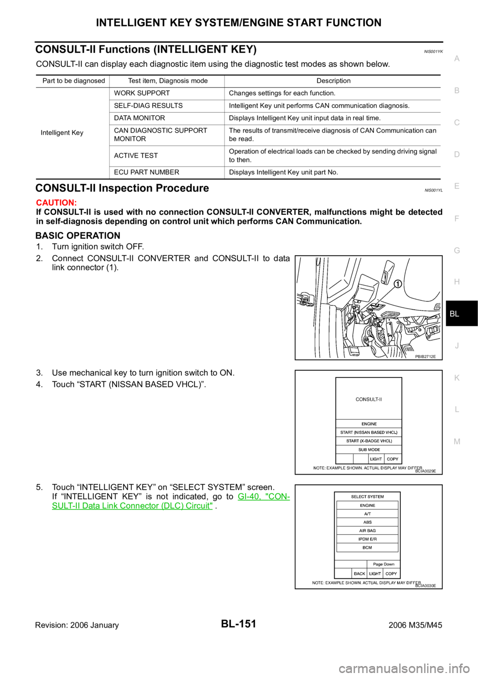
2. Connect CONSULT-II CONVERTER and CONSULT-II to data
link connector (1).
3. Use mechanical key to turn ignition switch to ON.
4. Touch “START (NISSAN BASED VHCL)”.
5. Touch “INTELLIGENT KEY” on “SELECT SYSTEM” screen.
If “INTELLIGENT KEY” is not indicated, go to GI-40, "
CON-
SULT-II Data Link Connector (DLC) Circuit" .
Part to be diagnosed Test item, Diagnosis mode Description
Intelligent KeyWORK SUPPORT Changes settings for each function.
SELF-DIAG RESULTS Intelligent Key unit performs CAN communication diagnosis.
DATA MONITOR Displays Intelligent Key unit input data in real time.
CAN DIAGNOSTIC SUPPORT
MONITORThe results of transmit/receive diagnosis of CAN Communication can
be read.
ACTIVE TESTOperation of electrical loads can be checked by sending driving signal
to then.
ECU PART NUMBER Displays Intelligent Key unit part No.
PBIB2712E
BCIA0029E
BCIA0030E
Page 1091 of 5621

BL-152
INTELLIGENT KEY SYSTEM/ENGINE START FUNCTION
Revision: 2006 January2006 M35/M45
6. Select diagnosis mode. “WORK SUPPORT”, “SELF-DIAG
RESULTS”, “CAN DIAG SUPPORT MNTR”, “DATA MONITOR”,
“ACTIVE TEST” and “ECU PART NUMBER” are available.
CONSULT-II Application ItemsNIS001YM
SELF-DIAGNOSTIC RESULTS
How to Read SELF-DIAGNOSTIC RESULTS
BCIA0031E
PIIB6280E
Suspect Systems
[DTC]Diagnostic item is detected when... Repair work Reference page
CAN COMM 1
[U1000]Malfunction is detected in CAN communicationPerform CAN communi-
cation system inspectionBL-181
CAN COMM 2
[U1010]Malfunction is detected in CAN communication caused
by Intelligent Key unit internal malfunctionReplace Intelligent Key
unit.BL-181
STRG COMM 1
[B2013]Communication malfunction with steering lock unit is
detectedCheck steering lock unitBL-157
STEERING LOCK UNIT
[B2551]Even if the communication with steering lock unit is
normally performed, the steering lock is malfunctioningReplace steering lock
unitBL-159
INTELLIGENT KEY
[B2552]Internal malfunction is detected in Intelligent Key unitReplace Intelligent Key
unit.BL-163
IGN POWER CIRCUIT
[B2553]It continues for 2 seconds or more that ON power sup-
ply input to Intelligent Key unit is excessively low when
the power supply position is in ON positionCheck Intelligent Key
unit ON power supply
inputBL-163
ACC POWER CIRCUIT
[B2554]It continues for 2 seconds or more that ACC power
supply input to Intelligent Key unit is excessively low
when the power supply position is in ACC or ON posi-
tionCheck Intelligent Key
unit ACC power supply
inputBL-164
STOP LAMP CIRCUIT
[B2555]5V or less is detected at both the stop lamp switch sig-
nal input circuit that is input to Intelligent Key unit and
the monitor input before stop lamp switchCheck stop lamp switchBL-167
Page 1149 of 5621

BL-210
TRUNK LID OPENER
Revision: 2006 January2006 M35/M45
System DescriptionNIS001ZO
Power is supplied at all times
through 50A fusible link (letter F, located in the fuse and fusible link box)
to BCM terminal 55,
through 10A fuse [No.21, located in the fuse block (J/B)]
to BCM terminal 42.
Ground is supplied
to BCM terminal 52
through body grounds M16 and M70.
When trunk lid opener cancel switch is ON and trunk lid opener switch is ON (pushed)
Ground is supplied
to BCM terminal 30
through trunk lid opener switch terminals 1and 2
through trunk lid opener cancel switch terminals 1and 3 and
through body grounds M16 and M70.
And power is supplied
through BCM terminal 68
to trunk lid opener actuator terminal 3.
Ground is supplied
to trunk lid opener actuator terminal 2
through body grounds B5, B40 and B131.
Then BCM open trunk lid opener actuator.
TRUNK LID OPENER OPERATION
When trunk lid opener switch or trunk button of Intelligent Key is ON, BCM opens trunk opener actuator.
BCM can open trunk lid opener actuator when
vehicle speed is less than 5 km/h (3MPH)
vehicle security system is disarmed or pre-armed phase
BCM does not open trunk lid opener actuator when
trunk lid opener cancel switch is OFF (CANSEL)
vehicle speed is more than 5 km/h (3MPH)
vehicle security system is armed or alarm phase
Intelligent Key is inserted in key slot
Page 1159 of 5621

BL-220
VEHICLE SECURITY (THEFT WARNING) SYSTEM
Revision: 2006 January2006 M35/M45
VEHICLE SECURITY (THEFT WARNING) SYSTEMPFP:28491
Component Parts and Harness Connector LocationNIS001ZT
PIIB5863E
Page 1160 of 5621

VEHICLE SECURITY (THEFT WARNING) SYSTEM
BL-221
C
D
E
F
G
H
J
K
L
MA
B
BL
Revision: 2006 January2006 M35/M45
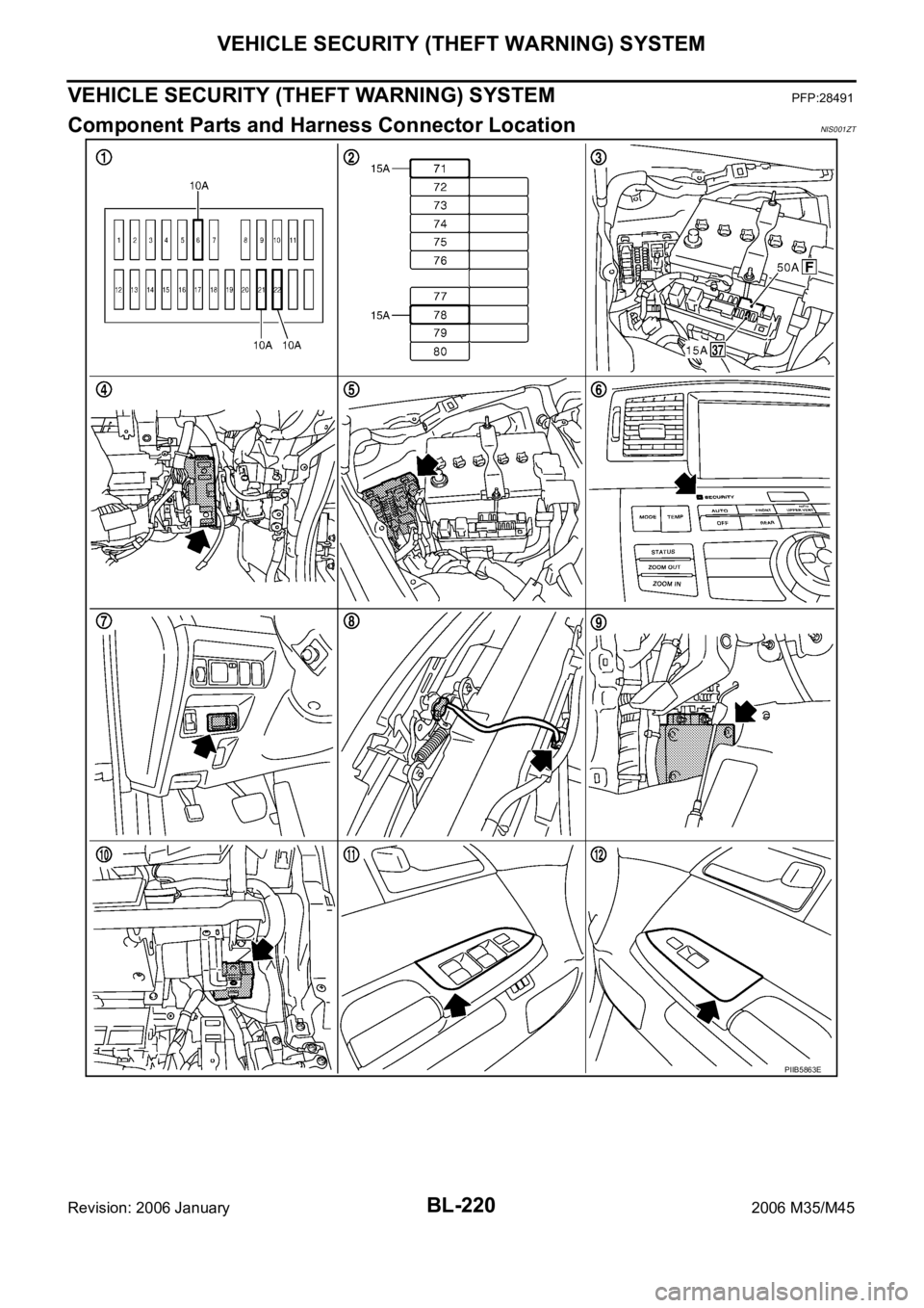
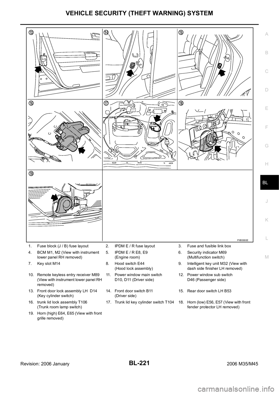
1. Fuse block (J / B) fuse layout 2. IPDM E / R fuse layout 3. Fuse and fusible link box
4. BCM M1, M2 (View with instrument
lower panel RH removed)5. IPDM E / R E8, E9
(Engine room)6. Security indicator M69
(Multifunction switch)
7. Key slot M14 8. Hood switch E44
(Hood lock assembly)9. Intelligent key unit M32 (View with
dash side finisher LH removed)
10. Remote keyless entry receiver M89
(View with instrument lower panel RH
removed)11. Power window main switch
D10, D11 (Driver side)12. Power window sub switch
D46 (Passenger side)
13. Front door lock assembly LH D14
(Key cylinder switch)14. Front door switch B11
(Driver side)15. Rear door switch LH B53
16. trunk lid lock assembly T106
(Trunk room lamp switch)17. Trunk lid key cylinder switch T104 18. Horn (low) E56, E57 (View with front
fender protector LH removed)
19. Horn (high) E64, E65 (View with front
grille removed)
PIIB5893E
Page 1161 of 5621

BL-222
VEHICLE SECURITY (THEFT WARNING) SYSTEM
Revision: 2006 January2006 M35/M45
System DescriptionNIS001ZU
DESCRIPTION
Operation Flow
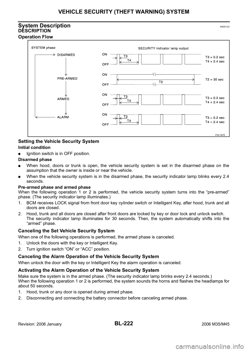
Setting the Vehicle Security System
Initial condition
Ignition switch is in OFF position.
Disarmed phase
When hood, doors or trunk is open, the vehicle security system is set in the disarmed phase on the
assumption that the owner is inside or near the vehicle.
When the vehicle security system is in the disarmed phase, the security indicator lamp blinks every 2.4
seconds.
Pre-armed phase and armed phase
When the following operation 1 or 2 is performed, the vehicle security system turns into the “pre-armed”
phase. (The security indicator lamp illuminates.)
1. BCM receives LOCK signal from front door key cylinder switch or Intelligent Key, after hood, trunk and all
doors are closed.
2. Hood, trunk and all doors are closed after front doors are locked by key or door lock and unlock switch.
The security indicator lamp illuminates for 30 seconds. Then, the system automatically shifts into the
“armed” phase.
Canceling the Set Vehicle Security System
When one of the following operations is performed, the armed phase is canceled.
1. Unlock the doors with the key or Intelligent Key.
2. Turn ignition switch “ON” or “ACC” position.
Canceling the Alarm Operation of the Vehicle Security System
When unlock the door with the key or Intelligent Key the alarm operation is canceled.
Activating the Alarm Operation of the Vehicle Security System
Make sure the system is in the armed phase. (The security indicator lamp brinks every 2.4 seconds.)
When the following operation 1 or 2 is performed, the system sounds the horns and flashes the headlamps for
about 50 seconds.
1. Hood, trunk or any door is opened during armed phase.
2. Disconnecting and connecting the battery connector before canceling armed phase.
PIIA1367E