2006 INFINITI M35 ECU
[x] Cancel search: ECUPage 1186 of 5621

VEHICLE SECURITY (THEFT WARNING) SYSTEM
BL-247
C
D
E
F
G
H
J
K
L
MA
B
BL
Revision: 2006 January2006 M35/M45
Diagnostic Procedure 5NIS00209
VEHICLE SECURITY HEADLAMP ALARM CHECK
1. CHECK HEADLAMP OPERATION
Check if headlamp operate by lighting switch.
Does headlamp come on when turning switch
“ON”?
YES >> Headlamp circuit is OK.
NO >> Check headlamp system. Refer to LT- 4 3 , "
HEADLAMP (FOR USA) - XENON TYPE -" , LT- 8 ,
"HEADLAMP (FOR USA) - CONVENTIONAL TYPE -" or LT- 7 9 , "HEADLAMP (FOR CANADA) -
DAYTIME LIGHT SYSTEM -" .
Diagnostic Procedure 6NIS0020A
DOOR LOCK AND UNLOCK SWITCH CHECK
1. CHECK DOOR LOCK AND UNLOCK SWITCH INPUT SIGNAL
Check if power door lock operated by door lock and unlock switch.
Do doors lock / unlock when using each door lock and unlock switches?
YES >> Door lock and unlock switch is OK.
NO >> Check door lock and unlock switch. Refer to BL-36, "
Check Door Lock and Unlock Switch"
Diagnostic Procedure 7NIS0020B
VEHCLE SECURITY HAZARD LAMP ALARM CHECK
1. CHECK HAZARD WARNING LAMP
Does hazard warning lamp flash with hazard switch?
YES or NO
YES >> Hazard warning lamp circuit is OK.
NO >> Check hazard circuit. Refer to LT- 2 11 , "
TURN SIGNAL AND HAZARD WARNING LAMPS" .
Page 1188 of 5621

IVIS (INFINITI VEHICLE IMMOBILIZER SYSTEM-NATS)
BL-249
C
D
E
F
G
H
J
K
L
MA
B
BL
Revision: 2006 January2006 M35/M45
NOTE:
If customer reports a “No start” condition, request ALL KEYS to be brought to an INFINITI dealer to
check for an IVIS (NATS) malfunction.
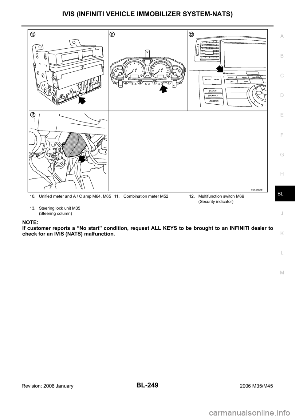
10. Unified meter and A / C amp M64, M65 11. Combination meter M5212. Multifunction switch M69
(Security indicator)
13. Steering lock unit M35
(Steering column)
PIIB5895E
Page 1189 of 5621

BL-250
IVIS (INFINITI VEHICLE IMMOBILIZER SYSTEM-NATS)
Revision: 2006 January2006 M35/M45
System DescriptionNIS0020D
DESCRIPTION
The IVIS (NATS) is an anti-theft system by registering an Intelligent Key ID in to the vehicle and prevents
the engine being started by an unregistered Intelligent Key. It has a higher protection against auto thefts
that duplicates mechanical key.
It performs the ID verification when starting the engine in the same way as the Intelligent Key system. But,
it performs the IVIS (NATS) ID verification when inserting the Intelligent Key and performs the Intelligent
Key ID verification when carrying the Intelligent Key.
The Intelligent Key system of FUGA (Y50) is not the same as the conventional models. The mechanical
key integrated in the Intelligent Key cannot start the engine. When the Intelligent Key battery is dis-
charged, the IVIS (NATS) ID verification memorized to the transponder integrated with Intelligent Key is
performed by inserting the Intelligent Key into the key slot. If the verification results are OK, the engine
start operation can be performed by the push-button ignition switch operation.
Locate the security indicator and apply the anti-theft system equipment sticker, forewarn that the IVIS
(NATS) is onboard with the model.
The security indicator always blinks when the Intelligent Key is removed from the key slot and when the
power supply position is in LOCK position.
Intelligent Key can be registered up to 4 keys (Including the standard ignition key) on request from the
owner.
The specified registration is required when replacing ECM, BCM or Intelligent Key. The registrations pro-
cedure for IVIS (NATS) and registration procedure for Intelligent Key when installing the Intelligent Key
unit, refer to CONSULT-II Operation Manual NATS-IVIS/NVIS.
Possible symptom of IVIS (NATS) malfunction is “Engine cannot start”. In FUGA (Y50), the engine can be
started with the Intelligent Key system and IVIS (NATS). Identify the possible causes according to “Work
Flow”, Refer to BL-272, "
Work Flow" .
If ECM other than Genuine NISSAN is installed, the engine cannot be started. For ECM replacement pro-
cedure, refer to BL-252, "
ECM Re-Communicating Function" .
PRECAUTIONS FOR KEY REGISTRATION
The key registration is a procedure that erases the current IVIS (NATS) ID once, and then re register a
new ID operation. Therefore the registered Intelligent Key is necessary for this procedure. Before starting
the registration operation collect all registered Intelligent Key from the customer
When registering the Intelligent Key, 2 registration procedures [IVIS (NATS) ID registration and Intelligent
Key ID registration] should be performed. The IVIS (NATS) ID registration is the procedure that registers
the ID stored into the transponder (integrated into Intelligent Key) to the BCM. The Intelligent Key ID reg-
istration is the procedure that registers the ID to the Intelligent Key unit. Each registration procedure
should be done separated.
When performing the Intelligent Key system registration only, the engine cannot be started by inserting the
key into the key slot. When performing the IVIS (NATS) registration only, the engine cannot be started by
the operation when carrying the key. The registrations of both systems should be performed.
SECURITY INDICATOR
Warn the outside that the vehicle is the model with IVIS (NATS).
The security indicator always blinks when the Intelligent Key is removed from the key slot and when the
ignition switch is in LOCK position.
NOTE:
Because security indicator is highly efficient, the battery is barely affected.
Page 1205 of 5621

BL-266
IVIS (INFINITI VEHICLE IMMOBILIZER SYSTEM-NATS)
Revision: 2006 January2006 M35/M45
Terminals and Reference Value for Steering Lock UnitNIS0020J
Terminals and Reference Value for BCMNIS0020K
71 LG PDU signalLOCK Steering lock: Lock Battery voltage
ACC Steering lock: Unlocked moment 0
72 B Ground — — 0 Te r m i -
nal
No.Wire
colorItemCondition
Voltage (V)
(Approx.) Push-
button
ignition
switch
positionOperation or conditions
Te r m i -
nal
No.Wire
colorItemCondition
Voltage (V)
(Approx.) Push-
button
ignition
switch
positionOperation or conditions
1 GR PDU signal LOCKPress push-button ignition switch with
Intelligent Key inside vehicle0
Battery voltage 0
(Battery voltage is detected when
pressing the push-button ignition
switch)
3 O Condition signal-1LOCK Steering lock: Lock 0
ACC
Steering lock: UnlockBattery voltage
ON Battery voltage
4 P/B Intelligent Key unit signalLOCK Steering lock: Lock Battery voltage
ACC
Steering lock: Unlock0
ON 0
5 B Ground — — 0
6 B Ground — — 0
7 LG Power source — — Battery voltage
8 L/Y Condition signal-2LOCK Steering lock: Lock Battery voltage
ACC
Steering lock: Unlock0
ON 0
Te r m i -
nal
No.Wire
colorItemCondition
Voltage (V)
(Approx.) Push-but-
ton igni-
tion
switch
positionOperation or conditions
21 GRNATS antenna amp.
(Built-in key slot)LOCKIgnition switch is pressed while
inserting the Intelligent Key into the
key slotJust after pressing ignition switch.
Pointer of tester should move
23 W/V Security indicator LOCKIntelligent Key is removed from key
slot and power supply position is in
LOCK positionBattery voltage
0
(Every 2.4 seconds)
25 W/RNATS antenna amp.
(Built-in key slot)LOCKIgnition switch is pressed while
inserting the Intelligent Key into the
key slotJust after pressing ignition switch.
Pointer of tester should move
37 LGKey slot
(Key switch signal)LOCKIntelligent Key is removed from key
slot0
Intelligent Key is inserted into key slot Battery voltage
Page 1213 of 5621

BL-274
IVIS (INFINITI VEHICLE IMMOBILIZER SYSTEM-NATS)
Revision: 2006 January2006 M35/M45
8. CHECK TURNING TIMING OF POWER SOURCE POSITION 2
Check all the Intelligent Keys for power source turning delay time after Push-button ignition switch is pushed
with Intelligent Key inserted into key slot. (Approx. 3 sec)
CAUTION:
Operate Push-button ignition switch without depressing the brake pedal.
No delay time exists>>GO TO 9.
Delay time exists when operated with particular Intelligent Key.>>Perform “C/U INITIALIZATION” referring to
CONSULT-II operation manual IVIS/NVIS NATS. In case that delay time still exists after the initial-
ization, replace the Intelligent Key.
Delay time exists when operated with any of the Intelligent Keys.>>Perform Trouble diagnosis symptom
chart 3. Refer to BL-180, "
Trouble Diagnosis Symptom Chart 3" .
9. CHECK ENGINE START FUNCTION
Check that engine can be started with Intelligent Key carried and inserted into the key slot respectively.
Engine can be started.>>GO TO 10.
Engine cannot be started.>>Inspect Trouble Diagnosis Flow Chart for IVIS (NATS). Refer to BL-275, "
Trou-
ble Diagnoses Flow Chart for IVIS (NATS)" .
10. CHECK SECURITY INDICATOR FUNCTION
Check Security Indicator for lighting up under the two conditions below.
Security Indicator lights off when Push-button ignition switch is pushed with Intelligent Key inserted into or
pulled out of the key slot.
Security Indicator blinks when Intelligent Key is pulled out and Push-button ignition switch is in lock posi-
tion.
Lighting up condition is normal.>>Inspection END.
Lighting up condition is malfunctioning.>>Perform Security Indicator Inspection. Refer to BL-277, "
Symptom
Chart for Security Indicator" .
Page 1216 of 5621

IVIS (INFINITI VEHICLE IMMOBILIZER SYSTEM-NATS)
BL-277
C
D
E
F
G
H
J
K
L
MA
B
BL
Revision: 2006 January2006 M35/M45
Symptom Chart for Security IndicatorNIS0020Q
Security indicator does not turn ON or flash.
CAUTION:
Follow Trouble Diagnosis Flowchart referring to “Diagnosis Procedure”. Determine malfunction-
ing condition before performing this diagnosis.
Make sure that vehicle is under the condition shown in “Conditions of vehicle” before starting
diagnosis.
Check systems shown in the “Action” column in this order.
CONDITIONS OF VEHICLE (OPERATING CONDITIONS)
Intelligent Key is not inserted into key slot.
Engine switch is not depressed.
Check Security Indicator HarnessNIS0020R
1. SECURITY INDICATOR LAMP ACTIVE TEST
With CONSULT-II
Check (“THEFT IND”) in “ACTIVE TEST” mode with CONSULT-II.
OK or NG
OK >> Security indicator lamp is OK.
NG >> GO TO 2.
Action Reference page
1. Check security indicator harnessBL-277
2. Replace BCMBCS-17
Perform operation shown on display indicator lamp
should illuminate.
PIIA7005E
Page 1217 of 5621

BL-278
IVIS (INFINITI VEHICLE IMMOBILIZER SYSTEM-NATS)
Revision: 2006 January2006 M35/M45
2. CHECK HARNESS CONTINUITY
1. Turn ignition switch OFF.
2. Disconnect multifunction switch (security indicator) connector.
3. Check voltage between multifunction switch (security indicator)
connector and ground.
OK or NG
OK >> Check the following.
Harness for open or short between BCM and multifunction switch (security indicator)
Security indicator lamp condition
NG >> Check the following.
15A fuse [No.37, located in fuse block (J/B)]
Harness for open or short between multifunction switch (security indicator) and fuse
DTC P1612 CHAIN of ECM-IMMUNIS0020S
Self-diagnostic results:
“CHAIN OF ECM-IMMU” displayed on CONSULT-II screen
First perform the “SELF-DIAG RESULTS” in “BCM” with CONSULT-II, then perform the trouble diagno-
sis of malfunction system indicated “SELF-DIAG RESULTS” of “BCM”. Refer to BCS-15, "
CAN Com-
munication Inspection Using CONSULT-II (Self-Diagnosis)" .
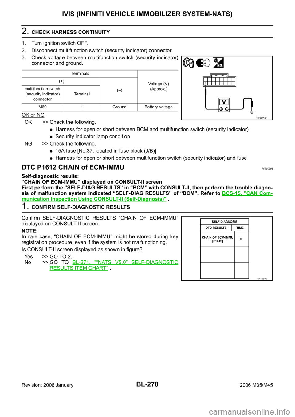
1. CONFIRM SELF-DIAGNOSTIC RESULTS
Confirm SELF-DIAGNOSTIC RESULTS “CHAIN OF ECM-IMMU”
displayed on CONSULT-II screen.
NOTE:
In rare case, “CHAIN OF ECM-IMMU” might be stored during key
registration procedure, even if the system is not malfunctioning.
Is CONSULT-II screen displayed as shown in figure?
Yes >> GO TO 2.
No >> GO TO BL-271, "
“NATS V5.0” SELF-DIAGNOSTIC
RESULTS ITEM CHART" .
Te r m i n a l s
Voltage (V)
(Approx.) (+)
(–) multifunction switch
(security indicator)
connectorTerminal
M69 1 Ground Battery voltage
PIIB6218E
PIIA1260E
Page 1282 of 5621

BRAKE PEDAL
BR-7
C
D
E
G
H
I
J
K
L
MA
B
BR
Revision: 2006 January2006 M35/M45
ADJUSTMENT
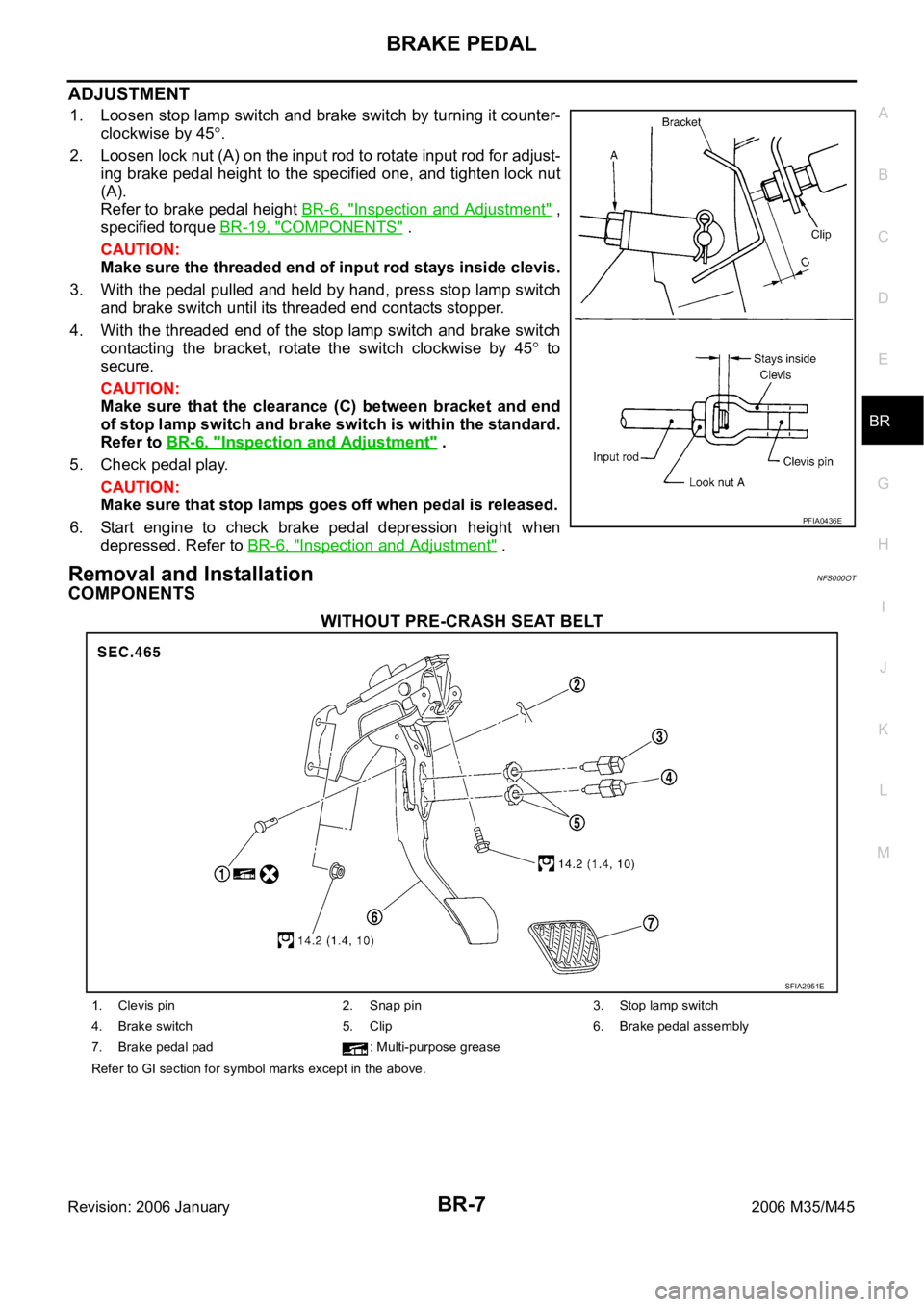
1. Loosen stop lamp switch and brake switch by turning it counter-
clockwise by 45
.
2. Loosen lock nut (A) on the input rod to rotate input rod for adjust-
ing brake pedal height to the specified one, and tighten lock nut
(A).
Refer to brake pedal height BR-6, "
Inspection and Adjustment" ,
specified torque BR-19, "
COMPONENTS" .
CAUTION:
Make sure the threaded end of input rod stays inside clevis.
3. With the pedal pulled and held by hand, press stop lamp switch
and brake switch until its threaded end contacts stopper.
4. With the threaded end of the stop lamp switch and brake switch
contacting the bracket, rotate the switch clockwise by 45
to
secure.
CAUTION:
Make sure that the clearance (C) between bracket and end
of stop lamp switch and brake switch is within the standard.
Refer to BR-6, "
Inspection and Adjustment" .
5. Check pedal play.
CAUTION:
Make sure that stop lamps goes off when pedal is released.
6. Start engine to check brake pedal depression height when
depressed. Refer to BR-6, "
Inspection and Adjustment" .
Removal and InstallationNFS000OT
COMPONENTS
WITHOUT PRE-CRASH SEAT BELT
PFIA0436E
SFIA2951E
1. Clevis pin 2. Snap pin 3. Stop lamp switch
4. Brake switch 5. Clip 6. Brake pedal assembly
7. Brake pedal pad : Multi-purpose grease
Refer to GI section for symbol marks except in the above.