2006 INFINITI M35 ECU
[x] Cancel search: ECUPage 1288 of 5621

BRAKE TUBE AND HOSE
BR-13
C
D
E
G
H
I
J
K
L
MA
B
BR
Revision: 2006 January2006 M35/M45
CAUTION:
All brake hoses and tubes must be free from excessive bending, twisting and pulling.
Make sure that there is no interference with other parts when turning steering both clockwise and
counterclockwise.
Brake tubes and hoses are an important safety part. Always disassemble the parts and retighten
their fittings, if a brake fluid leak is detected. Replace applicable part with a new one, if damaged
part is detected.
Be careful not to splash brake fluid on painted areas; it may cause paint damage. If brake fluid is
splashed on painted areas, wash it away with water immediately.
Cover the open end of brake tubes and hoses when disconnecting to prevent entrance of dirt.
Refill with new brake fluid “DOT 3”.
Never reuse drained brake fluid.
Removal and Installation of Front Brake Tube and Brake Hose NFS000OZ
REMOVAL
1. Drain brake fluid. Refer to BR-10, "Drain and Refill" .
2. Disconnect brake hose from brake tube, using a flare nut wrench.
3. Remove union bolt and remove brake hose from caliper assem-
bly.
4. Remove lock plate and remove brake hose from vehicle.
INSTALLATION
1. Assemble the union bolt and copper washer to the brake hose.
CAUTION:
Do not reuse copper washer.
2. Install brake hose by aligning with the protrusion on brake caliper assembly, and tighten union bolt to the
specified torque. Refer to BR-12, "
Hydraulic Circuit" .
3. Connect brake hose to brake tube, partially tighten flare nut by hand as much as possible, then secure it
to the bracket with lock plate.
4. Using a flare nut torque wrench, tighten flare nut to the specified torque. Refer to BR-12, "
Hydraulic Cir-
cuit" .
5. Refill brake fluid and bleed air. Refer to BR-11, "
Bleeding Brake System" .
Removal and Installation of Rear Brake Tube and Brake Hose NFS000P0
REMOVAL
1. Drain brake fluid. Refer to BR-10, "Drain and Refill" .
2. Disconnect brake hose from brake tube, using a flare nut wrench.
A. With out ICC B. With ICC 1. Front disc brake
2. Master cylinder 3. Brake booster 4. Rear disc brake
5. ABS actuator and electric unit (con-
trol unit)6. Connector 7. Brake hose
8. Brake tube : Flare nut
:18.2 Nꞏm (1.9 kg-m, 13 ft-lb): Flare nut
: 16.2 Nꞏm (1.7 kg-m, 12 ft-lb)
: Union bolt
:18.2 Nꞏm (1.9 kg-m, 13 ft-lb): Connector mounting bolt
: 7.0 Nꞏm (0.7 kg-m, 62 in-lb)
Refer to GI section for symbol marks in the figure.
SFIA2964E
Page 1289 of 5621
BR-14
BRAKE TUBE AND HOSE
Revision: 2006 January2006 M35/M45
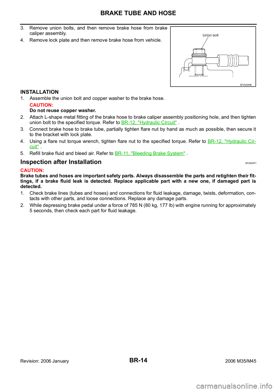
3. Remove union bolts, and then remove brake hose from brake
caliper assembly.
4. Remove lock plate and then remove brake hose from vehicle.
INSTALLATION
1. Assemble the union bolt and copper washer to the brake hose.
CAUTION:
Do not reuse copper washer.
2. Attach L-shape metal fitting of the brake hose to brake caliper assembly positioning hole, and then tighten
union bolt to the specified torque. Refer to BR-12, "
Hydraulic Circuit" .
3. Connect brake hose to brake tube, partially tighten flare nut by hand as much as possible, then secure it
to the bracket with lock plate.
4. Using a flare nut torque wrench, tighten flare nut to the specified torque. Refer to BR-12, "
Hydraulic Cir-
cuit" .
5. Refill brake fluid and bleed air. Refer to BR-11, "
Bleeding Brake System" .
Inspection after InstallationNFS000P1
CAUTION:
Brake tubes and hoses are important safety parts. Always disassemble the parts and retighten their fit-
tings, if a brake fluid leak is detected. Replace applicable part with a new one, if damaged part is
detected.
1. Check brake lines (tubes and hoses) and connections for fluid leakage, damage, twists, deformation, con-
tacts with other parts, and loose connections. Replace any damage parts.
2. While depressing brake pedal under a force of 785 N (80 kg, 177 lb) with engine running for approximately
5 seconds, then check each part for fluid leakage.
SFIA2049E
Page 1291 of 5621
BR-16
BRAKE MASTER CYLINDER
Revision: 2006 January2006 M35/M45
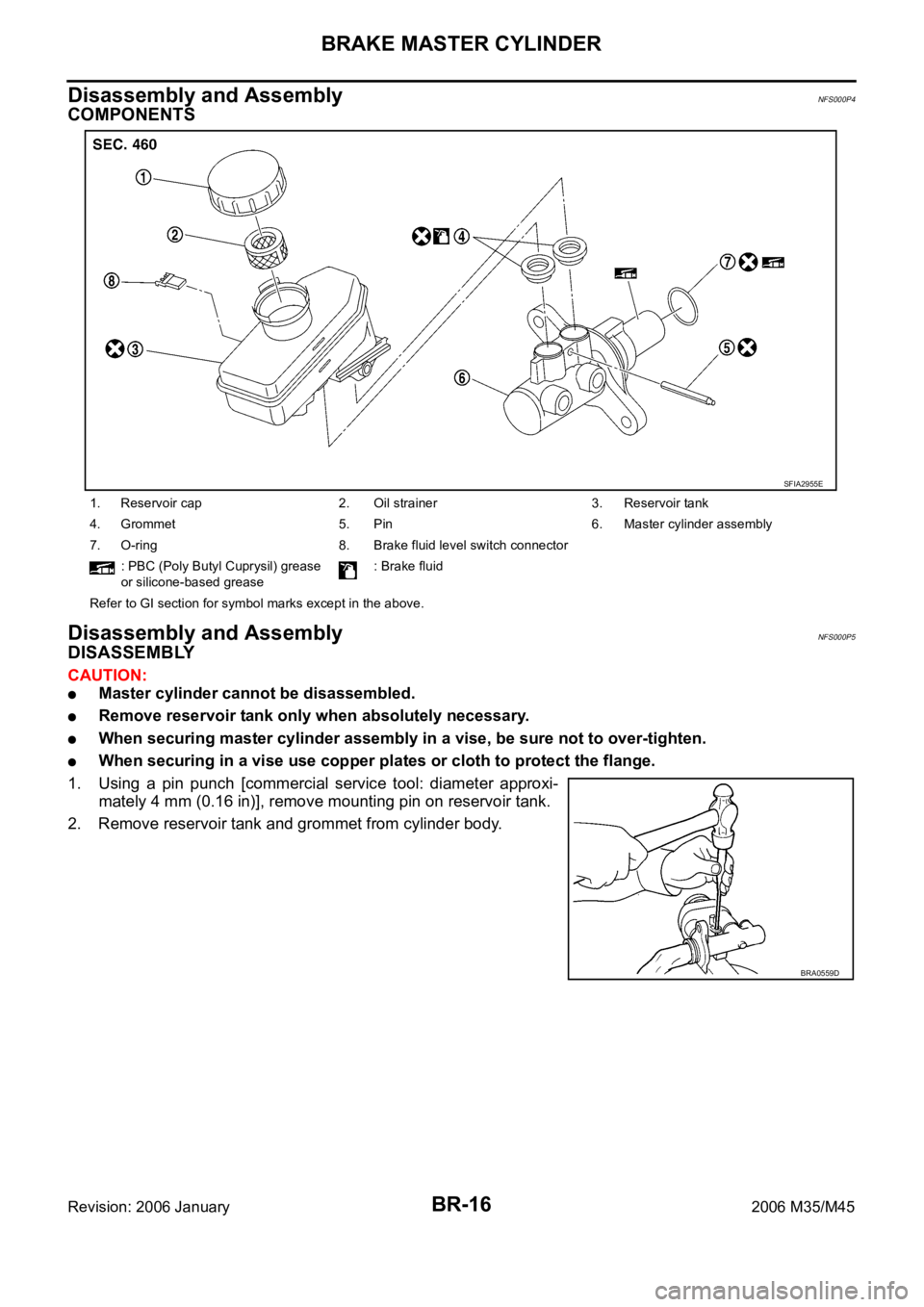
Disassembly and AssemblyNFS000P4
COMPONENTS
Disassembly and AssemblyNFS000P5
DISASSEMBLY
CAUTION:
Master cylinder cannot be disassembled.
Remove reservoir tank only when absolutely necessary.
When securing master cylinder assembly in a vise, be sure not to over-tighten.
When securing in a vise use copper plates or cloth to protect the flange.
1. Using a pin punch [commercial service tool: diameter approxi-
mately 4 mm (0.16 in)], remove mounting pin on reservoir tank.
2. Remove reservoir tank and grommet from cylinder body.
1. Reservoir cap 2. Oil strainer 3. Reservoir tank
4. Grommet 5. Pin 6. Master cylinder assembly
7. O-ring 8. Brake fluid level switch connector
: PBC (Poly Butyl Cuprysil) grease
or silicone-based grease: Brake fluid
Refer to GI section for symbol marks except in the above.
SFIA2955E
BRA0559D
Page 1292 of 5621
BRAKE MASTER CYLINDER
BR-17
C
D
E
G
H
I
J
K
L
MA
B
BR
Revision: 2006 January2006 M35/M45
ASSEMBLY
CAUTION:
Never use mineral oils such as kerosene, gasoline during the cleaning and assembly process.
Do not drop parts. If a part is dropped, do not use it.
1. Apply brake fluid to the grommet and attach it to the cylinder body.
CAUTION:
Do not reuse grommet.
2. Install reservoir tank onto the cylinder body.
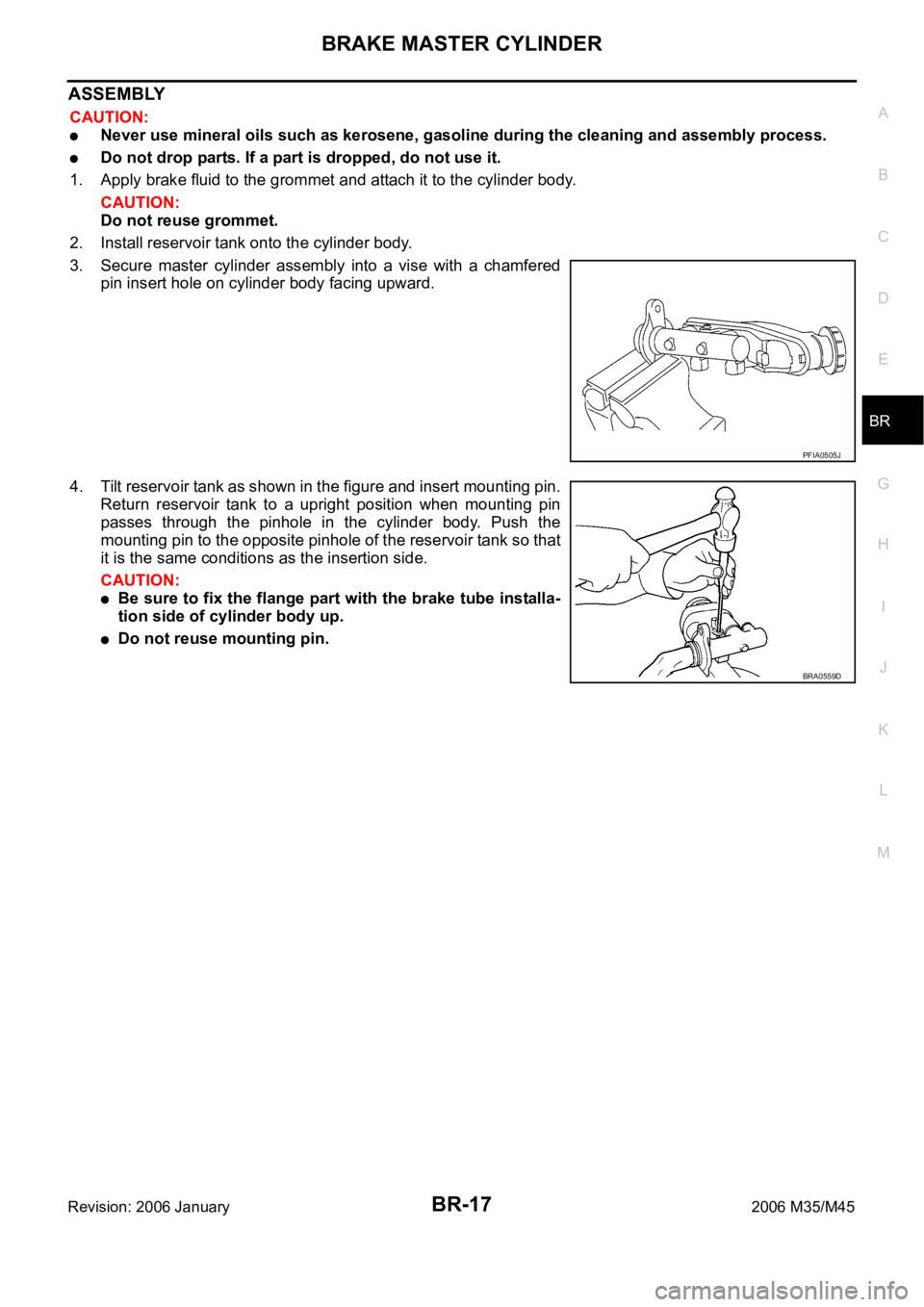
3. Secure master cylinder assembly into a vise with a chamfered
pin insert hole on cylinder body facing upward.
4. Tilt reservoir tank as shown in the figure and insert mounting pin.
Return reservoir tank to a upright position when mounting pin
passes through the pinhole in the cylinder body. Push the
mounting pin to the opposite pinhole of the reservoir tank so that
it is the same conditions as the insertion side.
CAUTION:
Be sure to fix the flange part with the brake tube installa-
tion side of cylinder body up.
Do not reuse mounting pin.
PFIA0505J
BRA0559D
Page 1299 of 5621
BR-24
FRONT DISC BRAKE
Revision: 2006 January2006 M35/M45
It is not necessary to remove bolts on torque member and brake hose except for disassembly or
replacement of caliper assembly. In this case, hang cylinder body with a wire so as not to stretch
brake hose.
Do not damage piston boot.
If any shim is subject to serious corrosion, replace it with a new one.
Always replace shim and shim cover as a set when replacing brake pads.
Keep rotor free from brake fluid.
Burnish the brake pads and disc rotor mutually contacting surfaces, after refinishing or replacing
rotors, after replacing pads, or if a soft pedal occurs at very low mileage. Refer to BR-28, "
BRAKE
BURNISHING PROCEDURE" .
Removal and Installation of Brake PadNFS000PD
REMOVAL
1. Remove tires from vehicle with power tool.
2. Remove lower sliding pin bolt.
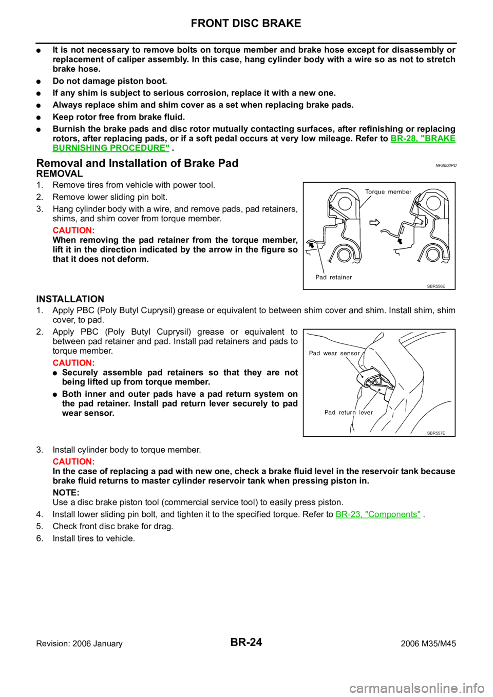
3. Hang cylinder body with a wire, and remove pads, pad retainers,
shims, and shim cover from torque member.
CAUTION:
When removing the pad retainer from the torque member,
lift it in the direction indicated by the arrow in the figure so
that it does not deform.
INSTALLATION
1. Apply PBC (Poly Butyl Cuprysil) grease or equivalent to between shim cover and shim. Install shim, shim
cover, to pad.
2. Apply PBC (Poly Butyl Cuprysil) grease or equivalent to
between pad retainer and pad. Install pad retainers and pads to
torque member.
CAUTION:
Securely assemble pad retainers so that they are not
being lifted up from torque member.
Both inner and outer pads have a pad return system on
the pad retainer. Install pad return lever securely to pad
wear sensor.
3. Install cylinder body to torque member.
CAUTION:
In the case of replacing a pad with new one, check a brake fluid level in the reservoir tank because
brake fluid returns to master cylinder reservoir tank when pressing piston in.
NOTE:
Use a disc brake piston tool (commercial service tool) to easily press piston.
4. Install lower sliding pin bolt, and tighten it to the specified torque. Refer to BR-23, "
Components" .
5. Check front disc brake for drag.
6. Install tires to vehicle.
SBR556E
SBR557E
Page 1302 of 5621
FRONT DISC BRAKE
BR-27
C
D
E
G
H
I
J
K
L
MA
B
BR
Revision: 2006 January2006 M35/M45
ASSEMBLY
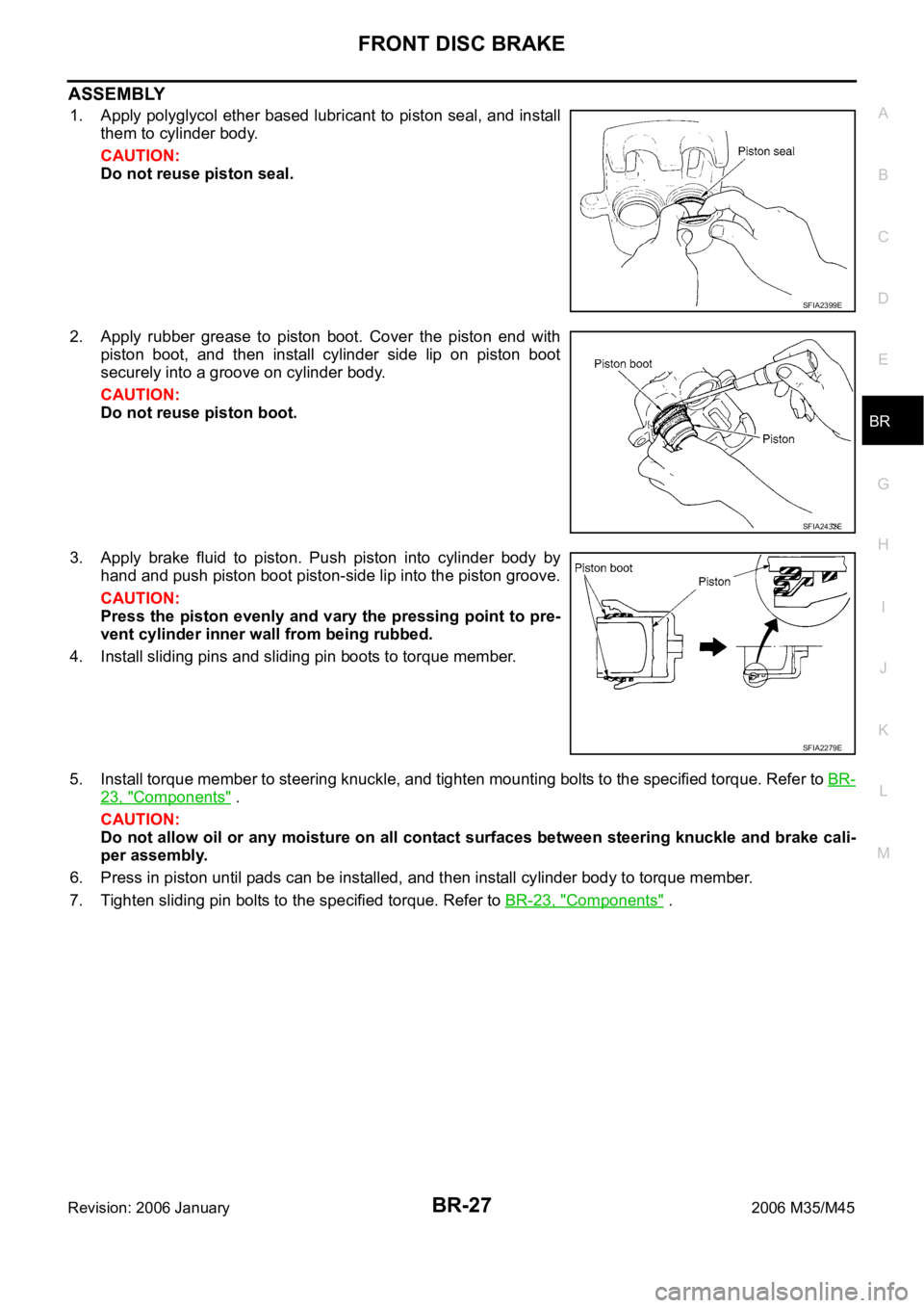
1. Apply polyglycol ether based lubricant to piston seal, and install
them to cylinder body.
CAUTION:
Do not reuse piston seal.
2. Apply rubber grease to piston boot. Cover the piston end with
piston boot, and then install cylinder side lip on piston boot
securely into a groove on cylinder body.
CAUTION:
Do not reuse piston boot.
3. Apply brake fluid to piston. Push piston into cylinder body by
hand and push piston boot piston-side lip into the piston groove.
CAUTION:
Press the piston evenly and vary the pressing point to pre-
vent cylinder inner wall from being rubbed.
4. Install sliding pins and sliding pin boots to torque member.
5. Install torque member to steering knuckle, and tighten mounting bolts to the specified torque. Refer to BR-
23, "Components" .
CAUTION:
Do not allow oil or any moisture on all contact surfaces between steering knuckle and brake cali-
per assembly.
6. Press in piston until pads can be installed, and then install cylinder body to torque member.
7. Tighten sliding pin bolts to the specified torque. Refer to BR-23, "
Components" .
SFIA2399E
SFIA2432E
SFIA2279E
Page 1303 of 5621
BR-28
FRONT DISC BRAKE
Revision: 2006 January2006 M35/M45
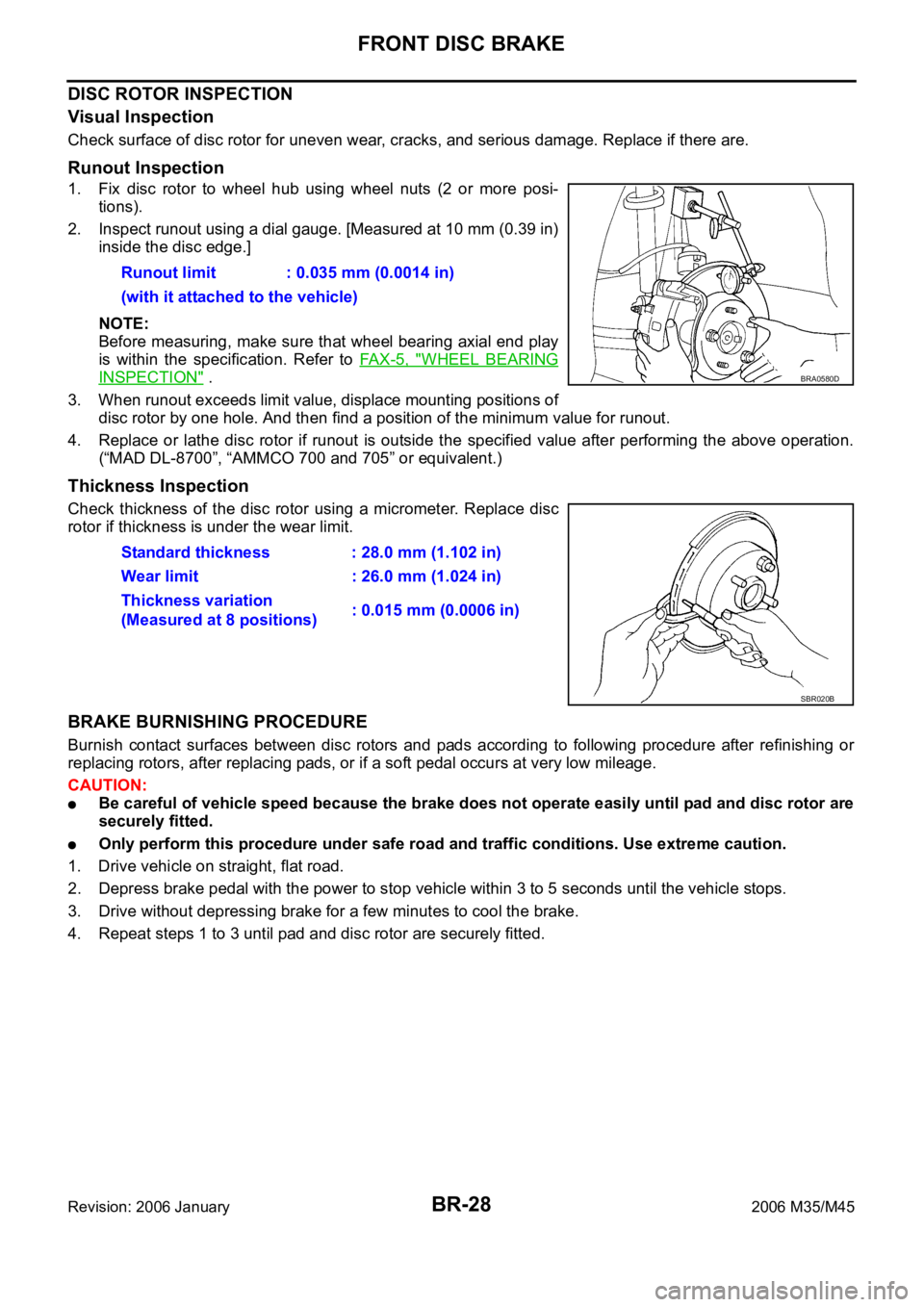
DISC ROTOR INSPECTION
Visual Inspection
Check surface of disc rotor for uneven wear, cracks, and serious damage. Replace if there are.
Runout Inspection
1. Fix disc rotor to wheel hub using wheel nuts (2 or more posi-
tions).
2. Inspect runout using a dial gauge. [Measured at 10 mm (0.39 in)
inside the disc edge.]
NOTE:
Before measuring, make sure that wheel bearing axial end play
is within the specification. Refer to FA X - 5 , "
WHEEL BEARING
INSPECTION" .
3. When runout exceeds limit value, displace mounting positions of
disc rotor by one hole. And then find a position of the minimum value for runout.
4. Replace or lathe disc rotor if runout is outside the specified value after performing the above operation.
(“MAD DL-8700”, “AMMCO 700 and 705” or equivalent.)
Thickness Inspection
Check thickness of the disc rotor using a micrometer. Replace disc
rotor if thickness is under the wear limit.
BRAKE BURNISHING PROCEDURE
Burnish contact surfaces between disc rotors and pads according to following procedure after refinishing or
replacing rotors, after replacing pads, or if a soft pedal occurs at very low mileage.
CAUTION:
Be careful of vehicle speed because the brake does not operate easily until pad and disc rotor are
securely fitted.
Only perform this procedure under safe road and traffic conditions. Use extreme caution.
1. Drive vehicle on straight, flat road.
2. Depress brake pedal with the power to stop vehicle within 3 to 5 seconds until the vehicle stops.
3. Drive without depressing brake for a few minutes to cool the brake.
4. Repeat steps 1 to 3 until pad and disc rotor are securely fitted. Runout limit : 0.035 mm (0.0014 in)
(with it attached to the vehicle)
BRA0580D
Standard thickness : 28.0 mm (1.102 in)
Wear limit : 26.0 mm (1.024 in)
Thickness variation
(Measured at 8 positions): 0.015 mm (0.0006 in)
SBR020B
Page 1308 of 5621
REAR DISC BRAKE
BR-33
C
D
E
G
H
I
J
K
L
MA
B
BR
Revision: 2006 January2006 M35/M45
CAUTION:
A piston sliding surface is plated. Do not polish with sandpaper.
Sliding Pin Bolt, Sliding Pin Boot
Check sliding pin bolt and sliding pin boot for wear, damage, and cracks. Replace if there are.
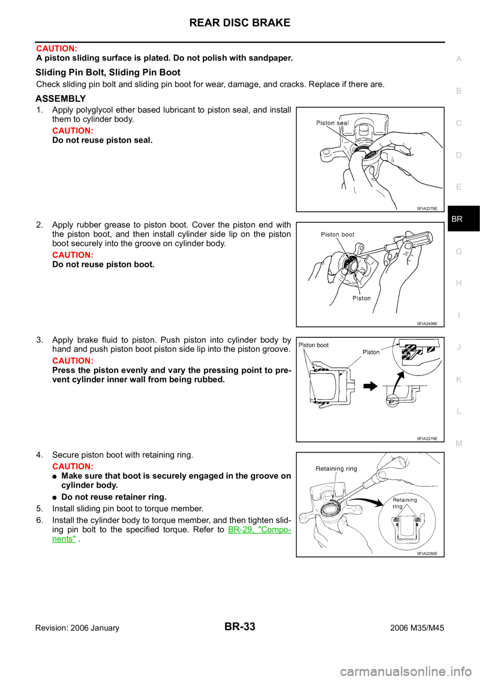
ASSEMBLY
1. Apply polyglycol ether based lubricant to piston seal, and install
them to cylinder body.
CAUTION:
Do not reuse piston seal.
2. Apply rubber grease to piston boot. Cover the piston end with
the piston boot, and then install cylinder side lip on the piston
boot securely into the groove on cylinder body.
CAUTION:
Do not reuse piston boot.
3. Apply brake fluid to piston. Push piston into cylinder body by
hand and push piston boot piston side lip into the piston groove.
CAUTION:
Press the piston evenly and vary the pressing point to pre-
vent cylinder inner wall from being rubbed.
4. Secure piston boot with retaining ring.
CAUTION:
Make sure that boot is securely engaged in the groove on
cylinder body.
Do not reuse retainer ring.
5. Install sliding pin boot to torque member.
6. Install the cylinder body to torque member, and then tighten slid-
ing pin bolt to the specified torque. Refer to BR-29, "
Compo-
nents" .
SFIA2278E
SFIA2498E
SFIA2279E
SFIA2280E