2006 INFINITI M35 stall
[x] Cancel search: stallPage 3604 of 5621
REAR WINDOW DEFOGGER
GW-85
C
D
E
F
G
H
J
K
L
MA
B
GW
Revision: 2006 January2006 M35/M45
BCM Power Supply and Ground Circuit CheckNIS0022R
First perform the “SELF-DIAG RESULTS” in “BCM” with CONSULT-II, when perform the each trouble
diagnosis. Refer to BCS-15, "
CAN Communication Inspection Using CONSULT-II (Self-Diagnosis)" .
1. CHECK FUSE
Check 15A fuse [No.1, located in the fuse block (J/B)]
Check 10A fuse [No.21, located in the fuse block (J/B)]
Check 50A fusible link (letter F located in the fuse and fusible link box).
NOTE:
Refer to GW-73, "
Component Parts and Harness Connector Location" .
OK or NG
OK >> GO TO 2.
NG >> If fuse is blown out, be sure to eliminate cause of malfunction before installing new fuse. Refer to
PG-3, "
POWER SUPPLY ROUTING CIRCUIT" .
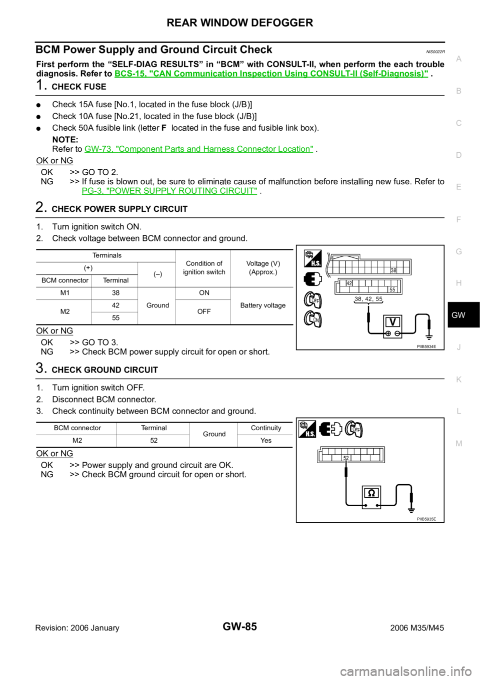
2. CHECK POWER SUPPLY CIRCUIT
1. Turn ignition switch ON.
2. Check voltage between BCM connector and ground.
OK or NG
OK >> GO TO 3.
NG >> Check BCM power supply circuit for open or short.
3. CHECK GROUND CIRCUIT
1. Turn ignition switch OFF.
2. Disconnect BCM connector.
3. Check continuity between BCM connector and ground.
OK or NG
OK >> Power supply and ground circuit are OK.
NG >> Check BCM ground circuit for open or short.
Terminals
Condition of
ignition switchVoltage (V)
(Approx.) (+)
(–)
BCM connector Terminal
M1 38
GroundON
Battery voltage
M242
OFF
55
PIIB5934E
BCM connector Terminal
GroundContinuity
M2 52 Yes
PIIB5935E
Page 3605 of 5621
GW-86
REAR WINDOW DEFOGGER
Revision: 2006 January2006 M35/M45
Rear Window Defogger Switch Circuit CheckNIS0022S
1. CHECK REAR WINDOW DEFOGGER SWITCH OPERATION
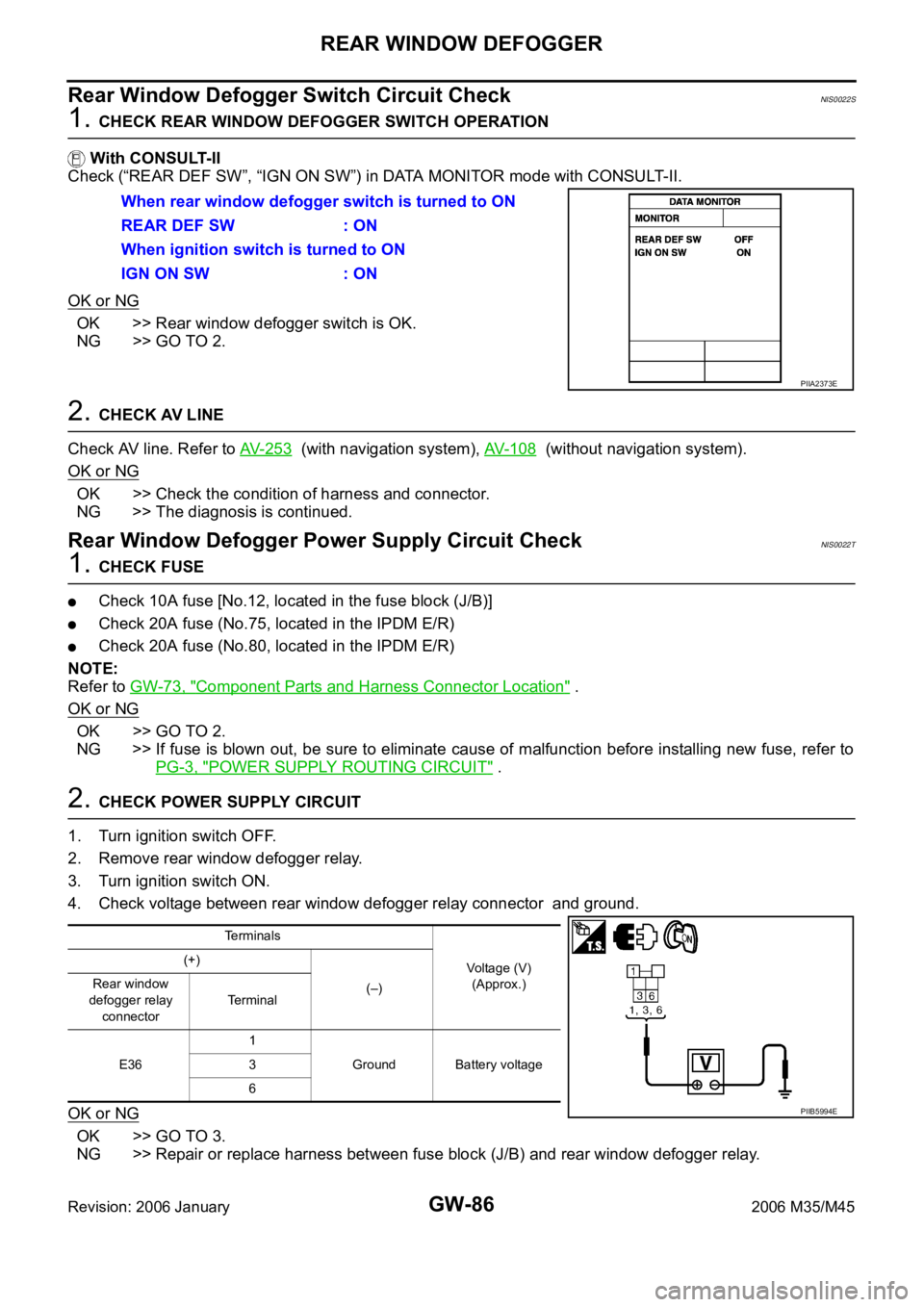
With CONSULT-II
Check (“REAR DEF SW”, “IGN ON SW”) in DATA MONITOR mode with CONSULT-II.
OK or NG
OK >> Rear window defogger switch is OK.
NG >> GO TO 2.
2. CHECK AV LINE
Check AV line. Refer to AV- 2 5 3
(with navigation system), AV- 1 0 8 (without navigation system).
OK or NG
OK >> Check the condition of harness and connector.
NG >> The diagnosis is continued.
Rear Window Defogger Power Supply Circuit CheckNIS0022T
1. CHECK FUSE
Check 10A fuse [No.12, located in the fuse block (J/B)]
Check 20A fuse (No.75, located in the IPDM E/R)
Check 20A fuse (No.80, located in the IPDM E/R)
NOTE:
Refer to GW-73, "
Component Parts and Harness Connector Location" .
OK or NG
OK >> GO TO 2.
NG >> If fuse is blown out, be sure to eliminate cause of malfunction before installing new fuse, refer to
PG-3, "
POWER SUPPLY ROUTING CIRCUIT" .
2. CHECK POWER SUPPLY CIRCUIT
1. Turn ignition switch OFF.
2. Remove rear window defogger relay.
3. Turn ignition switch ON.
4. Check voltage between rear window defogger relay connector and ground.
OK or NG
OK >> GO TO 3.
NG >> Repair or replace harness between fuse block (J/B) and rear window defogger relay. When rear window defogger switch is turned to ON
REAR DEF SW : ON
When ignition switch is turned to ON
IGN ON SW : ON
PIIA2373E
Terminals
Voltage (V)
(Approx.) (+)
(–) Rear window
defogger relay
connectorTerminal
E361
Ground Battery voltage 3
6
PIIB5994E
Page 3606 of 5621
REAR WINDOW DEFOGGER
GW-87
C
D
E
F
G
H
J
K
L
MA
B
GW
Revision: 2006 January2006 M35/M45
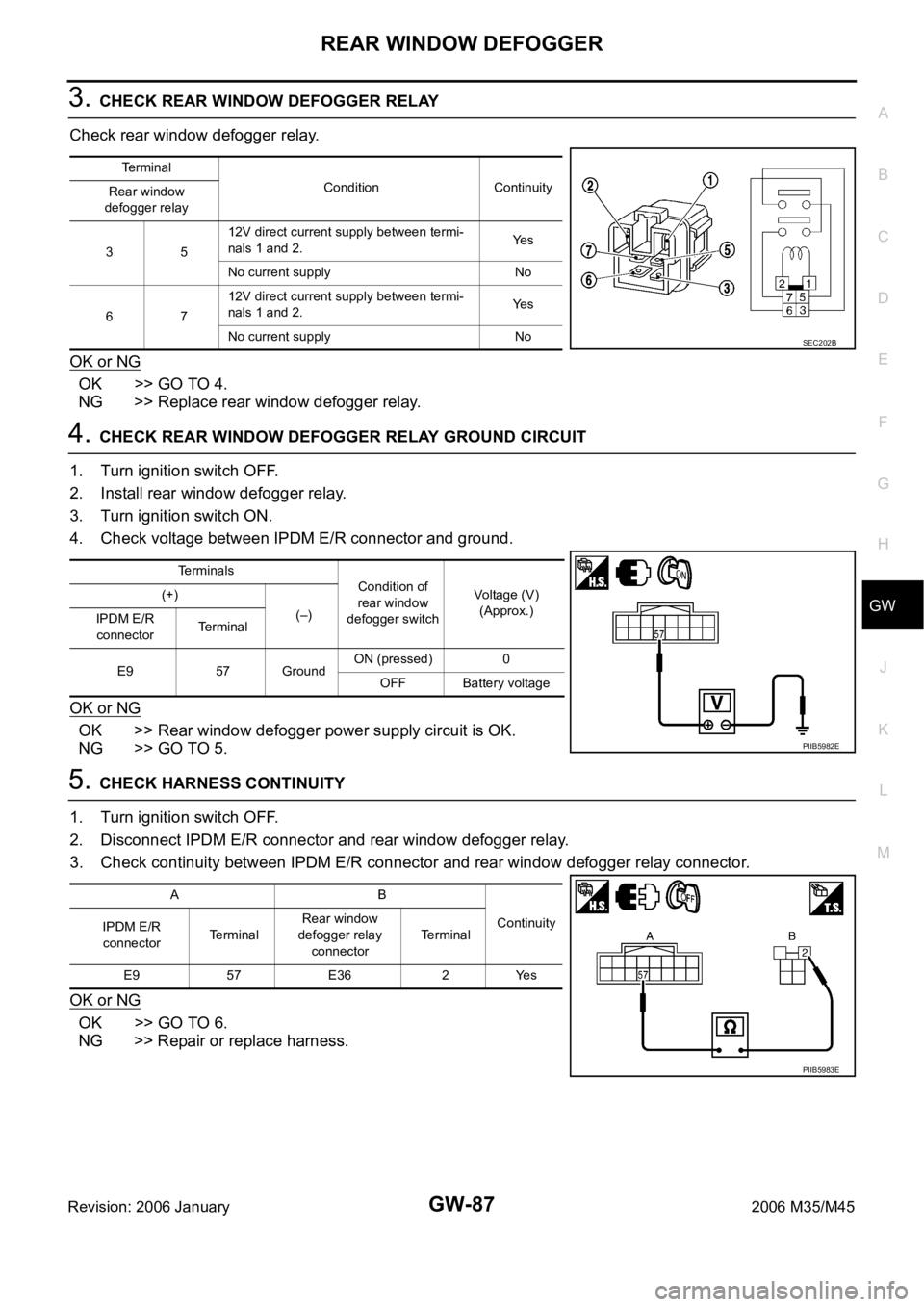
3. CHECK REAR WINDOW DEFOGGER RELAY
Check rear window defogger relay.
OK or NG
OK >> GO TO 4.
NG >> Replace rear window defogger relay.
4. CHECK REAR WINDOW DEFOGGER RELAY GROUND CIRCUIT
1. Turn ignition switch OFF.
2. Install rear window defogger relay.
3. Turn ignition switch ON.
4. Check voltage between IPDM E/R connector and ground.
OK or NG
OK >> Rear window defogger power supply circuit is OK.
NG >> GO TO 5.
5. CHECK HARNESS CONTINUITY
1. Turn ignition switch OFF.
2. Disconnect IPDM E/R connector and rear window defogger relay.
3. Check continuity between IPDM E/R connector and rear window defogger relay connector.
OK or NG
OK >> GO TO 6.
NG >> Repair or replace harness.
Terminal
Condition Continuity
Rear window
defogger relay
3512V direct current supply between termi-
nals 1 and 2.Ye s
No current supply No
6712V direct current supply between termi-
nals 1 and 2.Ye s
No current supply No
SEC202B
Terminals
Condition of
rear window
defogger switchVoltage (V)
(Approx.) (+)
(–)
IPDM E/R
connectorTerminal
E9 57 GroundON (pressed) 0
OFF Battery voltage
PIIB5982E
AB
Continuity
IPDM E/R
connectorTerminalRear window
defogger relay
connectorTerminal
E9 57 E36 2 Yes
PIIB5983E
Page 3608 of 5621
REAR WINDOW DEFOGGER
GW-89
C
D
E
F
G
H
J
K
L
MA
B
GW
Revision: 2006 January2006 M35/M45
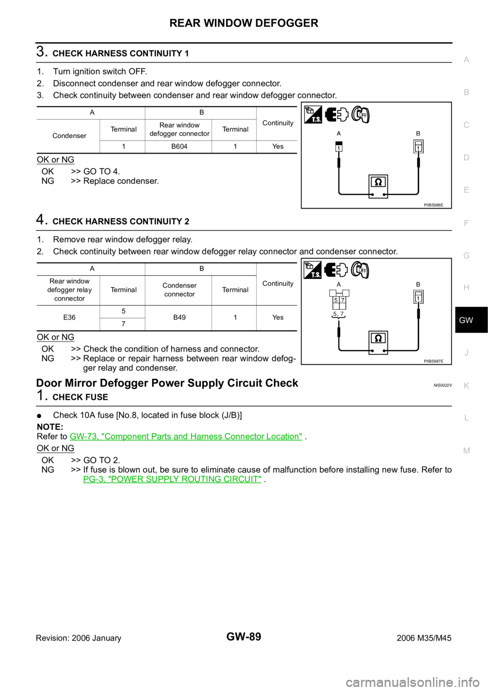
3. CHECK HARNESS CONTINUITY 1
1. Turn ignition switch OFF.
2. Disconnect condenser and rear window defogger connector.
3. Check continuity between condenser and rear window defogger connector.
OK or NG
OK >> GO TO 4.
NG >> Replace condenser.
4. CHECK HARNESS CONTINUITY 2
1. Remove rear window defogger relay.
2. Check continuity between rear window defogger relay connector and condenser connector.
OK or NG
OK >> Check the condition of harness and connector.
NG >> Replace or repair harness between rear window defog-
ger relay and condenser.
Door Mirror Defogger Power Supply Circuit CheckNIS0022V
1. CHECK FUSE
Check 10A fuse [No.8, located in fuse block (J/B)]
NOTE:
Refer to GW-73, "
Component Parts and Harness Connector Location" .
OK or NG
OK >> GO TO 2.
NG >> If fuse is blown out, be sure to eliminate cause of malfunction before installing new fuse. Refer to
PG-3, "
POWER SUPPLY ROUTING CIRCUIT" .
AB
Continuity
CondenserTerminalRear window
defogger connectorTerminal
1B6041Yes
PIIB5986E
AB
Continuity Rear window
defogger relay
connectorTerminalCondenser
connectorTerminal
E365
B49 1 Yes
7
PIIB5987E
Page 3639 of 5621
GW-120
DOOR MIRROR
Revision: 2006 January2006 M35/M45
DOOR MIRRORPFP:96301
Automatic Drive Positioner Interlocking Door Mirror NIS0023G
Automatic drive positioner interlocking door mirror. Refer to SE-11, "AUTOMATIC DRIVE POSITIONER" .
Removal and InstallationNIS0023H
CAUTION:
Be careful not to damage the mirror bodies.
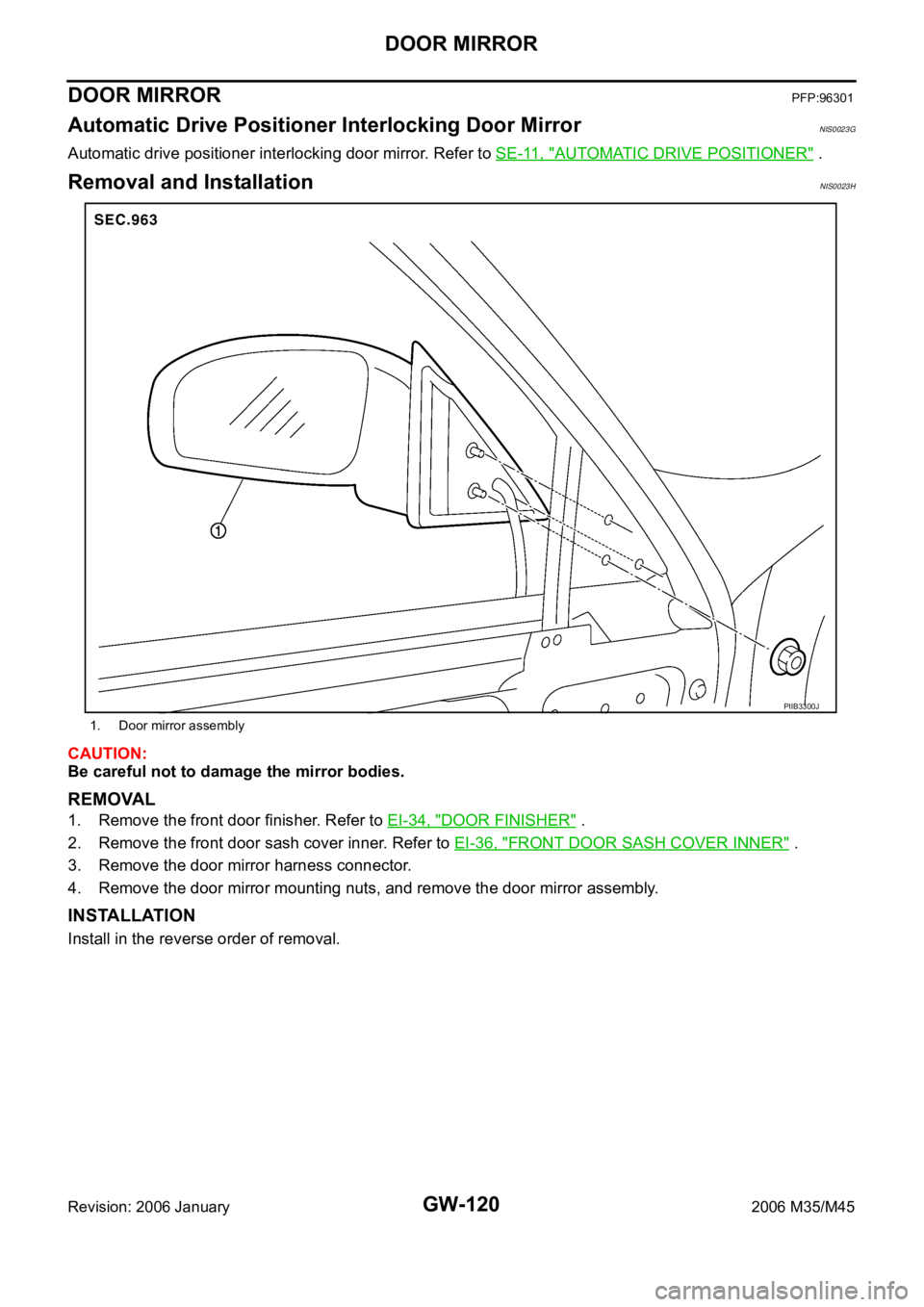
REMOVAL
1. Remove the front door finisher. Refer to EI-34, "DOOR FINISHER" .
2. Remove the front door sash cover inner. Refer to EI-36, "
FRONT DOOR SASH COVER INNER" .
3. Remove the door mirror harness connector.
4. Remove the door mirror mounting nuts, and remove the door mirror assembly.
INSTALLATION
Install in the reverse order of removal.
1. Door mirror assembly
PIIB3300J
Page 3641 of 5621
GW-122
DOOR MIRROR
Revision: 2006 January2006 M35/M45
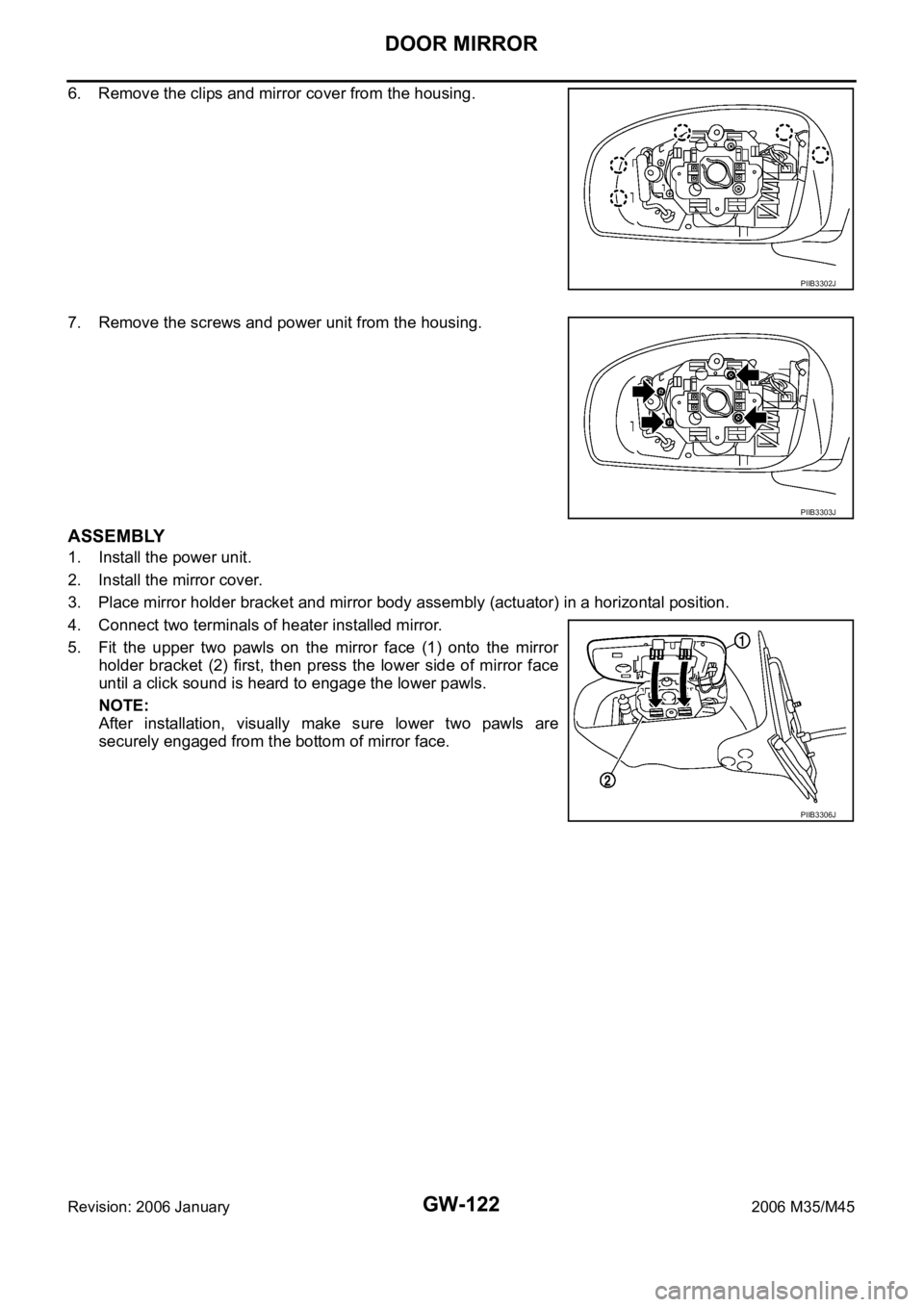
6. Remove the clips and mirror cover from the housing.
7. Remove the screws and power unit from the housing.
ASSEMBLY
1. Install the power unit.
2. Install the mirror cover.
3. Place mirror holder bracket and mirror body assembly (actuator) in a horizontal position.
4. Connect two terminals of heater installed mirror.
5. Fit the upper two pawls on the mirror face (1) onto the mirror
holder bracket (2) first, then press the lower side of mirror face
until a click sound is heard to engage the lower pawls.
NOTE:
After installation, visually make sure lower two pawls are
securely engaged from the bottom of mirror face.
PIIB3302J
PIIB3303J
PIIB3306J
Page 3644 of 5621
IDX-3
A
C
D
E
F
G
H
I
J
K
L B
IDX
ALPHABETICAL INDEX
Camshaft(VQ35DE) ........................................... EM-84
CAN .................................................................... DI-77
CAN - Wiring diagram ......... EC-174, EC-887, AT-106,
LAN-50
, LAN-91, LAN-132, LAN-179, LAN-226,
LAN-277
, LAN-323, LAN-369, LAN-419, LAN-469,
LAN-523
, LAN-566, LAN-609, LAN-658, LAN-707
CAN (Controller Area Network) ... SB-5, BL-26, BL-60,
BL-224
, GW-19, GW-75, GW-97, SE-16
CAN communication ........... EC-173, EC-176, EC-748,
EC-886
, EC-889, AT-32, AT-105, TF-13, TF-32, WT-12,
SB-5
, BL-26, BL-60, BL-224, GW-19, GW-75, GW-97,
SE-16
, WW-11
Canister-See EVAP canister ............... EC-42, EC-752
Center bearing assembly (propeller shaft) ........ PR-12
Center bearing disassembly (propeller shaft) .... PR-11
CHARGE - Wiring diagram ................................ SC-25
Charging system ................................................ SC-23
Chassis and body maintenance ........................ MA-29
CHIME - Wiring diagram ..................................... DI-64
CIGAR - Wiring diagram .................................. WW-49
Cigarette lighter ............................................... WW-49
Circuit breaker ................................................... PG-17
Clock ................................................................. DI-108
CLOCK - Wiring diagram .................................. DI-108
Closed loop control .............................. EC-32, EC-742
Closed loop control (Bank 1) ........... EC-509, EC-1236
Closed loop control (Bank 2) ........... EC-509, EC-1236
Collision diagnosis ........................................... SRS-50
Combination lamp, front, removal and installation ........
LT-76
Combination lamp, rear, removal and installation ........
LT-266
Combination meter ............................................... DI-5
COMPAS - Wiring diagram ............................... DI-106
Compass .......................................................... DI-105
Component Location (auto A/C) ...................... ATC-42
Compression pressure(VK45DE) .................... EM-233
Compression pressure(VQ35DE) .................... EM-101
Compressor special service tool ...................... ATC-16
Condenser ..................................................... ATC-165
Connecting rod bearing clearance(VK45DE) .. EM-273
Connecting rod bushing clearance .................. EM-142
Connecting rod bushing clearance(VK45DE) .. EM-268
Connecting rod(VK45DE) ................................ EM-268
Connecting rod(VQ35DE) ................................ EM-140
CONSULT-II Reference value (A/T) .................. AT-90
Control units (terminal arrangement) ............... PG-104
Control valve (A/T) ............................................. AT-38
Controller Area Network (CAN) ... SB-5, BL-26, BL-60,
BL-224
, GW-19, GW-75, GW-97, SE-16
Converter housing installation ............ AT-274, AT-277
COOL/F - Wiring diagram ................ EC-515, EC-1242
Coolant replacement(VQ35DE) ......................... MA-15
Cooling circuit (engine)(VK45DE) ...................... CO-38
Cooling circuit (engine)(VQ35DE) ....................... CO-9
Cooling fan motor ............ EC-524, EC-1249, EC-1250
Cooling fan(VK45DE) ........................................ CO-51
Cooling fan(VQ35DE) ........................................ CO-22
Cowl top ............................................................... EI-18
Cowl top cover .................................................... EI-18
Crankcase ventilation system - See Positive crankcase
ventilation ............................................. EC-51
, EC-761
Crankshaft position sensor (POS) ... EC-376, EC-1099
Crankshaft(VK45DE) ...................................... EM-250
Crankshaft(VQ35DE) ...................................... EM-140
Crash zone sensor .......................................... SRS-45
CUR/SE - Wiring diagram .. EC-539, EC-545, EC-551,
EC-557
, EC-1265, EC-1271, EC-1277, EC-1283
Cylinder block boring(VK45DE) ...................... EM-271
Cylinder block(VK45DE) ................................. EM-249
Cylinder block(VQ35DE) ................................. EM-123
Cylinder head bolt tightening(VK45DE) .......... EM-235
Cylinder head bolt tightening(VQ35DE) .......... EM-104
Cylinder head(VK45DE) ................................. EM-233
Cylinder head(VQ35DE) ................................. EM-101
D
D/LOCK - Wiring diagram .................................. BL-28
Daytime light system ........................................... LT-79
Daytime running light - See Daytime light system LT-79
DEF - Wiring diagram ............................ SB-7, SE-118
Diagnosis sensor unit ..................................... SRS-48
Diagnostic trouble code (DTC) for OBD system EC-16,
EC-58
, EC-726, EC-769
Direct clutch solenoid valve ............... AT-155, AT-157
Display and amp.assembly ............... ATC-53, ATC-66
Door glass ........................................... GW-63, GW-67
Door glass Fitting Adjustment(Front) ................ GW-66
Door glass Fitting Adjustment(Rear) ................. GW-70
Door lock .......................................................... BL-196
Door mirror ...................................................... GW-120
Door trim ............................................................. EI-34
Door, front ........................................... BL-190, GW-63
Door, rear ............................................ BL-190, GW-67
Drive belt inspection ......................................... MA-22
Drive belt inspection(VQ35DE) ......................... MA-14
Drive belt(VK45DE) ........................................ EM-174
Drive belt(VQ35DE) .......................................... EM-15
Drive shaft ......................................................... MA-38
Drive shaft (rear) ............................................... RAX-8
Driver air bag .................................................. SRS-38
DTRL - Wiring diagram ....................................... LT-84
Duct and grilles .............................................. ATC-144
E
ECM power supply EC-166
, EC-492, EC-879, EC-1211
ECM/PW - Wiring diagram ............... EC-493, EC-1212
ECTS - Wiring diagram ...................... EC-228, EC-950
Electric sunroof .................................................. RF-10
Electric throttle control actuator ........ EC-613, EC-624,
EC-1344
, EC-1356
Electric throttle control actuator (VK45DE) ..... EM-179
Electric throttle control actuator (VQ35DE) ....... EM-19
Electrical load signal circuit .............. EC-697, EC-1439
Electrical unit ................................................... PG-104
Electrical units location ...................................... PG-96
Page 3645 of 5621
IDX-4
ALPHABETICAL INDEX
Electronic ignition (EI) system ............. EC-33, EC-743
Engine control module (ECM) .......... EC-496, EC-1215
Engine control system diagram ........... EC-30, EC-740
Engine coolant temperature sensor (ECTS) ... EC-226,
EC-238
, EC-948, EC-961
Engine coolant(VK45DE) .................................. CO-40
Engine coolant(VQ35DE) ................................. CO-11
Engine oil filter replacement ............................. MA-26
Engine oil filter replacement(VQ35DE) ............. MA-19
Engine oil precautions .......................................... GI-8
Engine oil replacement(VQ35DE) ..................... MA-18
Engine oil(VK45DE) ........................................... LU-26
Engine oil(VQ35DE) ............................................ LU-7
Engine removal(VK45DE) ............................... EM-244
Engine removal(VQ35DE) .............................. EM-113
Engine room cover ............................................ EM-14
Engine room cover(VK45DE) ......................... EM-173
ETC1 - Wiring diagram .................... EC-614, EC-1345
ETC2 - Wiring diagram .................... EC-609, EC-1340
ETC3 - Wiring diagram .................... EC-620, EC-1352
EVAP canister ...................................... EC-42, EC-752
EVAP canister purge volume control solenoid valve ....
EC-412
, EC-420, EC-1132, EC-1140
EVAP canister vent control valve ...... EC-427, EC-434,
EC-1147
, EC-1154
EVAP control system (small leak) diagnosis .. EC-403,
EC-466
, EC-1124, EC-1185
EVAP control system pressure sensor ........... EC-440,
EC-443
, EC-450, EC-1160, EC-1163, EC-1170
EVAP control system purge flow monitoring diagnosis
EC-398
, EC-1119
EVAP vapor lines inspection ................. MA-21, MA-28
Evaporative emission (EVAP) system . EC-39, EC-749
Evaporator ..................................................... ATC-168
Exhaust manifold(VK45DE) ............................ EM-183
Exhaust system ................................................... EX-3
Exhaust system inspection ..................... EX-3, MA-29
Expansion valve ............................................. ATC-169
F
F/FOG - Wiring diagram ................................... LT-197
F/PUMP - Wiring diagram ................ EC-686, EC-1428
Final drive pre-inspection .................. FFD-16, RFD-19
Final drive removal and installation .. FFD-13, RFD-16
Floor trim ............................................................. EI-50
Flow charts ......................................................... GI-28
Fluid temperature sensor (A/T) ........................ AT-135
Fluorescent leak detector .............................. ATC-170
FPCM - Wiring diagram ................... EC-527, EC-1253
Freeze frame data ............................... EC-59, EC-770
Front brake solenoid valve ................. AT-151, AT-153
Front bumper ...................................................... EI-11
Front combination lamp removal and installation LT-76
Front door ............................. BL-190, BL-196, GW-63
Front passenger air bag .................................. SRS-42
Front seat belt .................................................... SB-30
Front seat belt pre-tensioner ..... SB-2, SRS-3, SRS-47
Front washer ...................................................... WW-4
Front wiper ......................................................... WW-4
FTS - Wiring diagram ....................................... AT-136
FTTS - Wiring diagram .... EC-345, EC-350, EC-1068,
EC-1073
Fuel cut control (at no load high engine speed) EC-34,
EC-744
Fuel filter replacement ......................................... FL-4
Fuel gauge ............................................................ DI-5
Fuel injection system (Bank 1) ......... EC-321, EC-332,
EC-1044
, EC-1055
Fuel injection system (Bank 2) ......... EC-321, EC-332,
EC-1044
, EC-1055
Fuel injector ................................................... EC-1420
Fuel injector and fuel tube(VK45DE) .............. EM-193
Fuel injector and fuel tube(VQ35DE) ................ EM-45
Fuel level sensor EC-475, EC-477, EC-479, EC-1194,
EC-1196
, EC-1198
Fuel line inspection .................................. FL-3, MA-25
Fuel line inspection(VQ35DE) .......................... MA-18
Fuel precautions ................................................... GI-6
Fuel pressure check ........................... EC-98, EC-809
Fuel pressure release ......................... EC-98, EC-809
Fuel pump ....................................... EC-685, EC-1427
Fuel pump and gauge .......................................... FL-4
Fuel pump control module .............. EC-525, EC-1251
Fuel pump dropping resistor ........... EC-525, EC-1251
Fuel system ......................................................... FL-3
Fuel tank ............................................................ FL-10
Fuel tank temperature sensor .......... EC-343, EC-349,
EC-1066
, EC-1072
Fuel tank vacuum relief valve ............. EC-42, EC-752
FUELB1 - Wiring diagram EC-323, EC-334, EC-1046,
EC-1057
FUELB2 - Wiring diagram EC-325, EC-336, EC-1048,
EC-1059
Fuse .................................................................. PG-17
Fuse and fusible link box ................................ PG-112
Fusible link ........................................................ PG-17
G
Gauges ................................................................. DI-5
Generator ........................................................... SC-23
Generator - See Alternator ................................ SC-23
Glass ........................ GW-11, GW-61, GW-63, GW-67
Grille - See Exterior ............................................ EI-16
Ground distribution ........................................... PG-46
H
H/LAMP - Wiring diagram ....................... LT-13
, LT-48
Harness connector .......................................... PG-102
Harness layout .................................................. PG-63
Hazard warning lamp ....................................... LT-211
Headlamp removal and installation .................... LT-76
Headlining - See Roof trim .................................. EI-52
Heated oxygen sensor 2 (bank 1) .... EC-286, EC-297,
EC-310
, EC-1009, EC-1020, EC-1033
Heated oxygen sensor 2 (bank 2) .... EC-286, EC-297,