Page 3582 of 5621
FRONT DOOR GLASS AND REGULATOR
GW-63
C
D
E
F
G
H
J
K
L
MA
B
GW
Revision: 2006 January2006 M35/M45
FRONT DOOR GLASS AND REGULATORPFP:80300
Removal and InstallationNIS00228
DOOR GLASS
Removal
1. Remove the front door finisher. Refer to EI-34, "DOOR FINISHER" .
2. Remove the front door sash cover inner. Refer to EI-36, "
FRONT DOOR SASH COVER INNER"
3. Operate the power window main switch to raise/lower the door
window until the glass mounting bolts can be seen.
4. Remove the glass mounting bolts.
1. Door glass 2. Module assembly 3. Power window motor
4. Regulator assembly 5. Door glass run
PIIB3287J
PIIB3288J
Page 3583 of 5621
GW-64
FRONT DOOR GLASS AND REGULATOR
Revision: 2006 January2006 M35/M45
5. While holding the door glass, raise it at the rear end to pull the
glass out of the sash toward the inside of the door.
Installation
Install in the reverse order of removal.
REGULATOR ASSEMBLY
Removal
1. Remove the front door finisher. Refer to EI-34, "DOOR FINISHER" .
2. Operate the power window main switch to raise/lower the door
window until the glass mounting bolts can be seen.
3. Remove the glass mounting bolts.
4. Raise up the door glass and hold with a suction lifter A.
5. Remove the mounting bolts, and remove the module assembly.
6. Disconnect the harness connector for the module assembly, and unclip the harness from the inside.
Installation
Install in the reverse order of removal.
SIIA1779J
PIIB3288J
PIIB3510J
Page 3584 of 5621

FRONT DOOR GLASS AND REGULATOR
GW-65
C
D
E
F
G
H
J
K
L
MA
B
GW
Revision: 2006 January2006 M35/M45
Inspection after Removal
Check the regulator assembly for the following items. If a malfunc-
tion is detected, replace or grease it.
Wire wear
Regulator deformation
Grease condition for each sliding part
The arrows in the figure show the application points of the multi-pur-
pose grease.
Disassembly and AssemblyNIS00229
REGULATOR ASSEMBLY
Disassembly
1. Remove power window motor from module assembly.
2. Remove regulator assembly from module assembly.
Assembly
Assemble in the reverse order of disassembly.
Inspection after InstallationNIS0022A
SYSTEM INITIALIZATION
If any of the following work has been done, initialize the system.
Electric power supply to power window switch or motor is interrupted by blown fuse or disconnecting bat-
tery cable, etc.
Removal and installation of the regulator assembly.
Removal and installation of the motor from the regulator assembly.
Removal and installation of the harness connector of the power window switch.
Operate the regulator assembly as a unit.
Removal and installation of the door glass.
Removal and installation of the door glass run.
Initialization
After installing each component to the vehicle, follow the steps below.
1. Disconnect the minus terminal of battery or disconnect power window switch's harness connector tempo-
rarily, then reconnect after at least 1 minute.
2. Turn ignition switch ON.
3. Open the window to its full width by operating the power window switch. (Exclude this pocedure if the win-
dow is already fully opened)
4. Fully draw the power window switch in up direction (auto close position) and hold, keep holding the switch
even when window is completely closed and then release afeter 3 second has passed.
5. Inspection of the anti-pinch system function.
NOTE:
Initialization may be cancelled with continuous opening and closing operation.In this case, initialize the
system.
INSPECT THE FUNCTION OF THE ANTI-PINCH SYSTEM.
1. Fully open the door glass.
2. Place a wooden piece (wooden hammer handle etc.) at near fully closed position.
3. Carry out fully closing operation with auto up switch.
Check that the glass reverses without pinching the wooden piece, is lowered approx.150 mm (5.91 in) or
for 2 seconds and then stops.
The glass should not be raised with power window main switch operated while it is reversing or lowering.
PIIB3290J
Page 3586 of 5621
REAR DOOR GLASS AND REGULATOR
GW-67
C
D
E
F
G
H
J
K
L
MA
B
GW
Revision: 2006 January2006 M35/M45
REAR DOOR GLASS AND REGULATORPFP:82300
Removal and InstallationNIS0022B
DOOR GLASS
Removal
1. Remove the rear door finisher. Refer to EI-34, "DOOR FINISHER" .
2. Remove the rear door sash cover inner. Refer to EI-36, "
REAR DOOR SASH COVER INNER" .
3. Remove the rear door inner frame.
1. Rear door inner frame 2. Outer corner cover 3. Lower sash
4. Door glass 5. Regulator assembly 6. Power window motor
7. Door glass run
PIIB3293J
PIIB3294J
Page 3587 of 5621
GW-68
REAR DOOR GLASS AND REGULATOR
Revision: 2006 January2006 M35/M45
4. Remove the fixing bolt and pull up the outer corner cover (1) to
remove outward.
5. Remove the rear door sash fixing nut and the door side TORX
bolt (T30) (1).
6. Remove the harness clip and pull out the rear door sash from
the door panel.
7. Operate the power window switch to raise/lower the door win-
dow until the glass mounting bolts can be seen.
8. Remove the glass mounting bolts.
9. Remove the door glass from the inside of door panel.
10. Remove the door glass run.
Installation
Install in the reverse order of removal.
REGULATOR ASSEMBLY
Removal
1. Remove the rear door finisher. Refer to EI-34, "DOOR FINISHER" .
2. Remove the rear door inner frame.
PIIB3295J
PIIB3296J
PIIB3297J
PIIB3294J
Page 3588 of 5621
REAR DOOR GLASS AND REGULATOR
GW-69
C
D
E
F
G
H
J
K
L
MA
B
GW
Revision: 2006 January2006 M35/M45
3. Operate the power window switch to raise/lower the door win-
dow until the glass mounting bolts can be seen.
4. Remove the glass mounting bolts.
5. Raise up the door glass and hold with a suction lifter A.
6. Disconnect the connector for the regulator assembly.
7. Remove the regulator mounting bolts, and remove the regulator
from the door panel.
Installation
Install in the reverse order of removal.
Inspection after Removal
Check the regulator assembly for the following items. If a malfunction is detected, replace or grease it.
Gear wear
Regulator deformation
Grease condition for each sliding part
The arrows in the figure show the application points of the multi-pur-
pose grease.
PIIB3297J
PIIB3511J
PIIB3298J
PIIB3299J
Page 3589 of 5621

GW-70
REAR DOOR GLASS AND REGULATOR
Revision: 2006 January2006 M35/M45
Disassembly and AssemblyNIS0022C
REGULATOR ASSEMBLY
Disassembly
Remove power window motor from regulator assembly.
Assembly
Assemble in the reverse order of disassembly.
Inspection after InstallationNIS0022D
SYSTEM INITIALIZATION
If any of the following work has been done, initialize the system.
Electric power sauce to power window switch or motor is interrupted by broken fuse or disconnecting bat-
tery cable, etc.
Removal and installation of the regulator assembly.
Removal and installation of the motor from the regulator assembly.
Removal and installation of the harness connector of the power window switch.
Operate the regulator assembly as a unit.
Removal and installation of the door glass.
Removal and installation of the door glass run.
Initialization
After installing each component to the vehicle, follow the steps below.
1. Disconnect the minus terminal of battery or disconnect power window switch's harness connector tempo-
rarily, then reconnect after at least 1 minute.
2. Turn ignition switch ON.
3. Open the window to its full width by operating the power window switch. (Exclude this pocedure if the win-
dow is already fully opened)
4. Fully draw the power window switch in up direction (auto close position) and hold, keep holding the switch
even when window is completely closed and then release afeter 3 second has passed.
5. Inspection of the anti-pinch system function.
NOTE:
Initialization may be cancelled with continuous opening and closing operation.In this case, initialize the
system.
INSPECT THE FUNCTION OF THE ANTI-PINCH SYSTEM
1. Fully open the door glass.
2. Place a wooden piece (wooden hammer handle etc.) at near fully closed position.
3. Carry out fully closing operation with auto up switch.
Check that the glass reverses without pinching the wooden piece, is lowered approx.150mm (5.91in) or
for 2 seconds and then stops.
The glass should not be raised with power window main switch operated while it is reversing or lowering.
CAUTION:
Do not inspect with pinching a part of worker's body, a hand etc. Work carefully not to be pinched.
Check that auto up function is normal before inspection following the system initialization.
FITTING INSPECTION
Make sure the glass is securely fit into the glass run groove.
Lower the glass slightly [approx. 10 to 20 mm (0.39 to 0.79 in)], and make sure the clearance to the sash
is parallel. If the clearance between the glass and sash is not parallel, loosen the regulator mounting bolts,
guide rail mounting bolts, and glass and carrier plate mounting bolts to correct the glass position.
Page 3591 of 5621
GW-72
INSIDE MIRROR
Revision: 2006 January2006 M35/M45
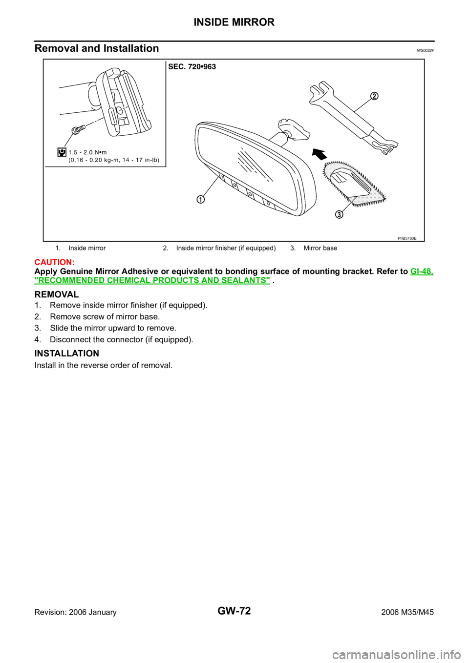
Removal and InstallationNIS0022F
CAUTION:
Apply Genuine Mirror Adhesive or equivalent to bonding surface of mounting bracket. Refer to GI-48,
"RECOMMENDED CHEMICAL PRODUCTS AND SEALANTS" .
REMOVAL
1. Remove inside mirror finisher (if equipped).
2. Remove screw of mirror base.
3. Slide the mirror upward to remove.
4. Disconnect the connector (if equipped).
INSTALLATION
Install in the reverse order of removal.
1. Inside mirror 2. Inside mirror finisher (if equipped) 3. Mirror base
PIIB5780E


 to
remove outward.
5. Remove the rear door sash fixing nut and")