2006 INFINITI M35 combination meter
[x] Cancel search: combination meterPage 1500 of 5621
WARNING CHIME
DI-67
C
D
E
F
G
H
I
J
L
MA
B
DI
Revision: 2006 January2006 M35/M45
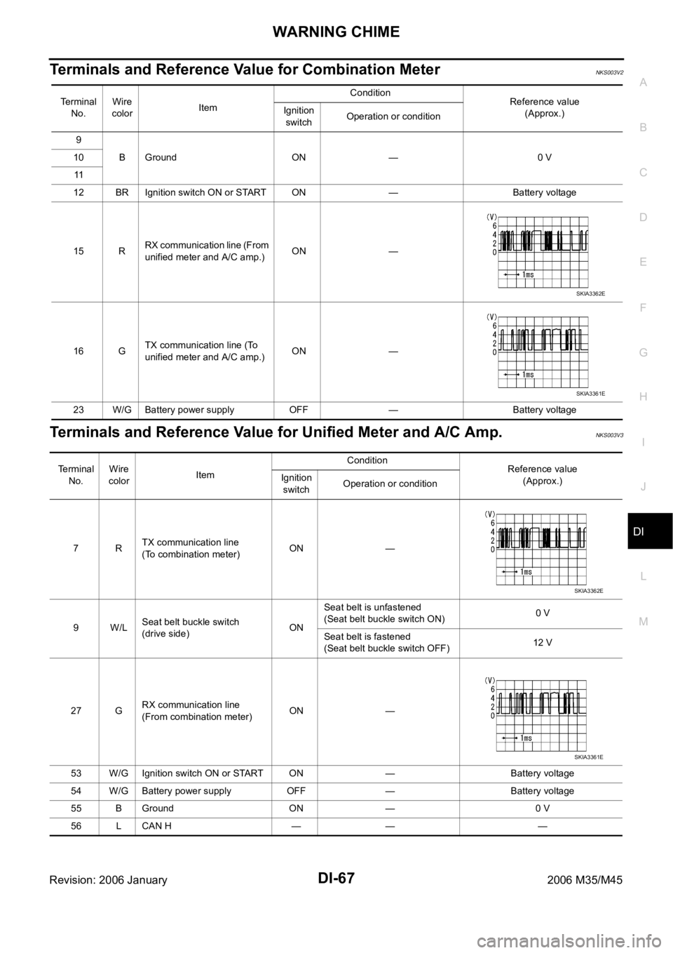
Terminals and Reference Value for Combination MeterNKS003V2
Terminals and Reference Value for Unified Meter and A/C Amp.NKS003V3
Te r m i n a l
No.Wire
colorItemCondition
Reference value
(Approx.) Ignition
switchOperation or condition
9
B Ground ON — 0 V 10
11
12 BR Ignition switch ON or START ON — Battery voltage
15 RRX communication line (From
unified meter and A/C amp.)ON —
16 GTX communication line (To
unified meter and A/C amp.)ON —
23 W/G Battery power supply OFF — Battery voltage
SKIA3362E
SKIA3361E
Terminal
No.Wire
colorItemCondition
Reference value
(Approx.) Ignition
switchOperation or condition
7RTX communication line
(To combination meter)ON —
9W/LSeat belt buckle switch
(drive side)ONSeat belt is unfastened
(Seat belt buckle switch ON)0 V
Seat belt is fastened
(Seat belt buckle switch OFF)12 V
27 GRX communication line
(From combination meter)ON —
53 W/G Ignition switch ON or START ON — Battery voltage
54 W/G Battery power supply OFF — Battery voltage
55 B Ground ON — 0 V
56 L CAN H — — —
SKIA3362E
SKIA3361E
Page 1505 of 5621
DI-72
WARNING CHIME
Revision: 2006 January2006 M35/M45
2. CHECK UNIFIED METER AND A/C AMP. (CONSULT-II)
Perform self-diagnosis of unified meter and A/C amp. Refer to DI-71, "
CONSULT-II Function (METER A/C
AMP)" .
Self
-diagnostic results content
No malfunction detected>> INSPECTION END
Malfunction detected>> Check applicable parts, and repair or replace corresponding parts.
SYMPTOM CHART
Meter Buzzer Circuit InspectionNKS003V8
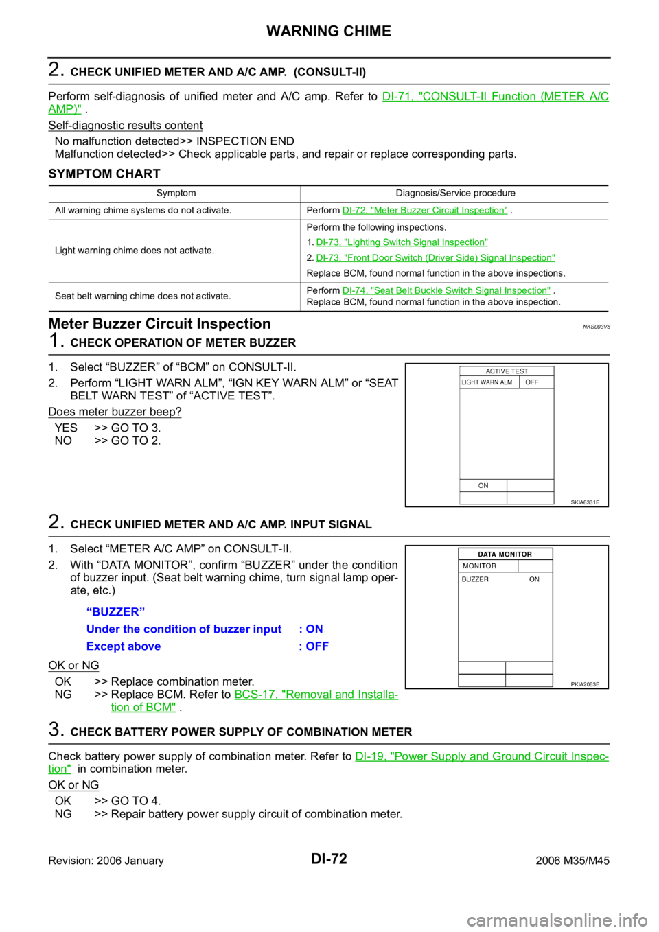
1. CHECK OPERATION OF METER BUZZER
1. Select “BUZZER” of “BCM” on CONSULT-II.
2. Perform “LIGHT WARN ALM”, “IGN KEY WARN ALM” or “SEAT
BELT WARN TEST” of “ACTIVE TEST”.
Does meter buzzer beep?
YES >> GO TO 3.
NO >> GO TO 2.
2. CHECK UNIFIED METER AND A/C AMP. INPUT SIGNAL
1. Select “METER A/C AMP” on CONSULT-II.
2. With “DATA MONITOR”, confirm “BUZZER” under the condition
of buzzer input. (Seat belt warning chime, turn signal lamp oper-
ate, etc.)
OK or NG
OK >> Replace combination meter.
NG >> Replace BCM. Refer to BCS-17, "
Removal and Installa-
tion of BCM" .
3. CHECK BATTERY POWER SUPPLY OF COMBINATION METER
Check battery power supply of combination meter. Refer to DI-19, "
Power Supply and Ground Circuit Inspec-
tion" in combination meter.
OK or NG
OK >> GO TO 4.
NG >> Repair battery power supply circuit of combination meter.
Symptom Diagnosis/Service procedure
All warning chime systems do not activate. Perform DI-72, "
Meter Buzzer Circuit Inspection" .
Light warning chime does not activate.Perform the following inspections.
1.DI-73, "
Lighting Switch Signal Inspection"
2.DI-73, "Front Door Switch (Driver Side) Signal Inspection"
Replace BCM, found normal function in the above inspections.
Seat belt warning chime does not activate.Perform DI-74, "
Seat Belt Buckle Switch Signal Inspection" .
Replace BCM, found normal function in the above inspection.
SKIA6331E
“BUZZER”
Under the condition of buzzer input : ON
Except above : OFF
PKIA2063E
Page 1513 of 5621
DI-80
LANE DEPARTURE WARNING SYSTEM
Revision: 2006 January2006 M35/M45
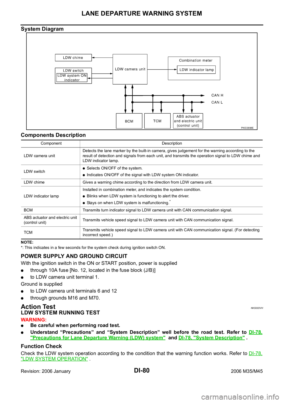
System Diagram
Components Description
NOTE:
*: This indicates in a few seconds for the system check during ignition switch ON.
POWER SUPPLY AND GROUND CIRCUIT
With the ignition switch in the ON or START position, power is supplied
through 10A fuse [No. 12, located in the fuse block (J/B)]
to LDW camera unit terminal 1.
Ground is supplied
to LDW camera unit terminals 6 and 12
through grounds M16 and M70.
Action TestNKS003VH
LDW SYSTEM RUNNING TEST
WAR NING :
Be careful when performing road test.
Understand “Precautions” and “System Description” well before the road test. Refer to DI-78,
"Precautions for Lane Departure Warning (LDW) system" and DI-78, "System Description" .
Function Check
Check the LDW system operation according to the condition that the warning function works. Refer to DI-78,
"LDW SYSTEM OPERATION" .
PKIC0698E
Component Description
LDW camera unitDetects the lane marker by the built-in camera, gives judgement for the warning according to the
result of detection and signals from each unit, and transmits the operation signal to LDW chime and
LDW indicator lamp.
LDW switch
Selects ON/OFF of the system.
Indicates ON/OFF of the signal with LDW system ON indicator.
LDW chime Gives a warning chime according to the direction from LDW camera unit.
LDW indicator lampInstalled in combination meter, and indicates the system condition.
Blinks when LDW system is functioning to alert the driver.
Stays on when LDW system is malfunctioning.*
BCM Transmits turn indicator signal to LDW camera unit with CAN communication signal.
ABS actuator and electric unit
(control unit)Transmits vehicle speed signal to LDW camera unit with CAN communication signal.
TCM Transmits vehicle speed signal to LDW camera unit with CAN communication signal. (For detecting
incorrect speed.)
Page 1528 of 5621
LANE DEPARTURE WARNING SYSTEM
DI-95
C
D
E
F
G
H
I
J
L
MA
B
DI
Revision: 2006 January2006 M35/M45
Trouble DiagnosisNKS003VN
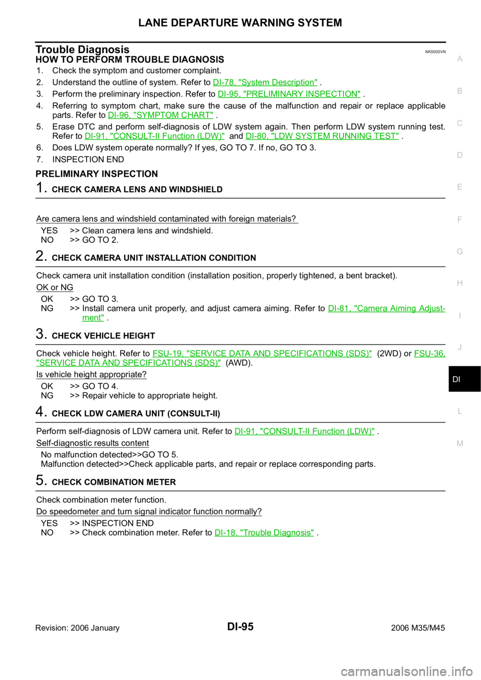
HOW TO PERFORM TROUBLE DIAGNOSIS
1. Check the symptom and customer complaint.
2. Understand the outline of system. Refer to DI-78, "
System Description" .
3. Perform the preliminary inspection. Refer to DI-95, "
PRELIMINARY INSPECTION" .
4. Referring to symptom chart, make sure the cause of the malfunction and repair or replace applicable
parts. Refer to DI-96, "
SYMPTOM CHART" .
5. Erase DTC and perform self-diagnosis of LDW system again. Then perform LDW system running test.
Refer to DI-91, "
CONSULT-II Function (LDW)" and DI-80, "LDW SYSTEM RUNNING TEST" .
6. Does LDW system operate normally? If yes, GO TO 7. If no, GO TO 3.
7. INSPECTION END
PRELIMINARY INSPECTION
1. CHECK CAMERA LENS AND WINDSHIELD
Are camera lens and windshield contaminated with foreign materials?
YES >> Clean camera lens and windshield.
NO >> GO TO 2.
2. CHECK CAMERA UNIT INSTALLATION CONDITION
Check camera unit installation condition (installation position, properly tightened, a bent bracket).
OK or NG
OK >> GO TO 3.
NG >> Install camera unit properly, and adjust camera aiming. Refer to DI-81, "
Camera Aiming Adjust-
ment" .
3. CHECK VEHICLE HEIGHT
Check vehicle height. Refer to FSU-19, "
SERVICE DATA AND SPECIFICATIONS (SDS)" (2WD) or FSU-36,
"SERVICE DATA AND SPECIFICATIONS (SDS)" (AWD).
Is vehicle height appropriate?
OK >> GO TO 4.
NG >> Repair vehicle to appropriate height.
4. CHECK LDW CAMERA UNIT (CONSULT-II)
Perform self-diagnosis of LDW camera unit. Refer to DI-91, "
CONSULT-II Function (LDW)" .
Self
-diagnostic results content
No malfunction detected>>GO TO 5.
Malfunction detected>>Check applicable parts, and repair or replace corresponding parts.
5. CHECK COMBINATION METER
Check combination meter function.
Do speedometer and turn signal indicator function normally?
YES >> INSPECTION END
NO >> Check combination meter. Refer to DI-18, "
Trouble Diagnosis" .
Page 1535 of 5621
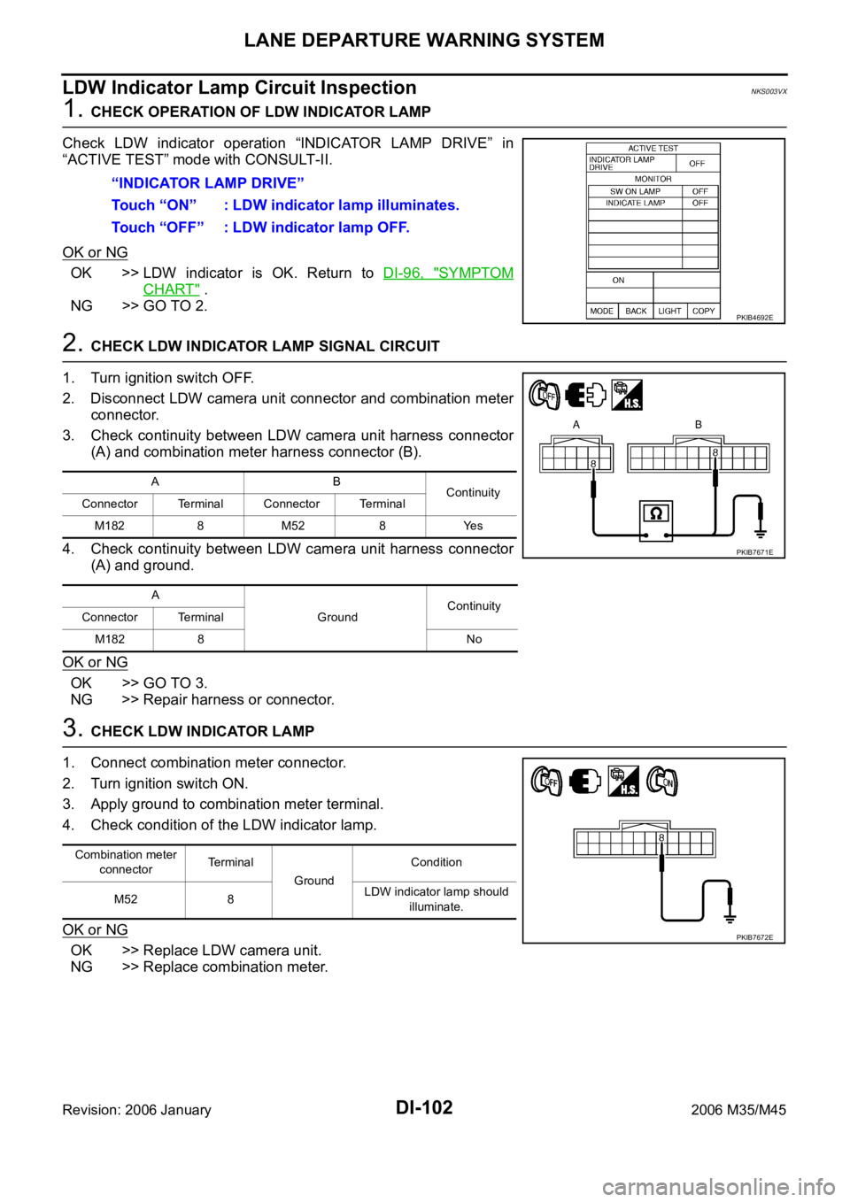
DI-102
LANE DEPARTURE WARNING SYSTEM
Revision: 2006 January2006 M35/M45
LDW Indicator Lamp Circuit InspectionNKS003VX
1. CHECK OPERATION OF LDW INDICATOR LAMP
Check LDW indicator operation “INDICATOR LAMP DRIVE” in
“ACTIVE TEST” mode with CONSULT-II.
OK or NG
OK >> LDW indicator is OK. Return to DI-96, "SYMPTOM
CHART" .
NG >> GO TO 2.
2. CHECK LDW INDICATOR LAMP SIGNAL CIRCUIT
1. Turn ignition switch OFF.
2. Disconnect LDW camera unit connector and combination meter
connector.
3. Check continuity between LDW camera unit harness connector
(A) and combination meter harness connector (B).
4. Check continuity between LDW camera unit harness connector
(A) and ground.
OK or NG
OK >> GO TO 3.
NG >> Repair harness or connector.
3. CHECK LDW INDICATOR LAMP
1. Connect combination meter connector.
2. Turn ignition switch ON.
3. Apply ground to combination meter terminal.
4. Check condition of the LDW indicator lamp.
OK or NG
OK >> Replace LDW camera unit.
NG >> Replace combination meter.“INDICATOR LAMP DRIVE”
Touch “ON” : LDW indicator lamp illuminates.
Touch “OFF” : LDW indicator lamp OFF.
PKIB4692E
AB
Continuity
Connector Terminal Connector Terminal
M182 8 M52 8 Yes
A
GroundContinuity
Connector Terminal
M182 8 No
PKIB7671E
Combination meter
connectorTe r m i n a l
GroundCondition
M52 8LDW indicator lamp should
illuminate.
PKIB7672E
Page 1579 of 5621
![INFINITI M35 2006 Factory Service Manual EC-36
[VQ35DE]
AUTOMATIC SPEED CONTROL DEVICE (ASCD)
Revision: 2006 January2006 M35/M45
AUTOMATIC SPEED CONTROL DEVICE (ASCD)PFP:18930
System DescriptionNBS004S8
INPUT/OUTPUT SIGNAL CHART
*: This sign INFINITI M35 2006 Factory Service Manual EC-36
[VQ35DE]
AUTOMATIC SPEED CONTROL DEVICE (ASCD)
Revision: 2006 January2006 M35/M45
AUTOMATIC SPEED CONTROL DEVICE (ASCD)PFP:18930
System DescriptionNBS004S8
INPUT/OUTPUT SIGNAL CHART
*: This sign](/manual-img/42/57023/w960_57023-1578.png)
EC-36
[VQ35DE]
AUTOMATIC SPEED CONTROL DEVICE (ASCD)
Revision: 2006 January2006 M35/M45
AUTOMATIC SPEED CONTROL DEVICE (ASCD)PFP:18930
System DescriptionNBS004S8
INPUT/OUTPUT SIGNAL CHART
*: This signal is sent to the ECM through CAN communication line
BASIC ASCD SYSTEM
Refer to Owner's Manual for ASCD operating instructions.
Automatic Speed Control Device (ASCD) allows a driver to keep vehicle at predetermined constant speed
without depressing accelerator pedal. Driver can set vehicle speed in advance between approximately 40 km/
h (25 MPH) and 144 km/h (89 MPH).
ECM controls throttle angle of electric throttle control actuator to regulate engine speed.
Operation status of ASCD is indicated by CRUISE lamp and SET lamp in combination meter. If any malfunc-
tion occurs in ASCD system, it automatically deactivates control.
NOTE:
Always drive vehicle in safe manner according to traffic conditions and obey all traffic laws.
SET OPERATION
Press MAIN switch. (The CRUISE lamp in combination meter illuminates.)
When vehicle speed reaches a desired speed between approximately 40 km/h (25 MPH) and 144 km/h (89
MPH), press SET/COAST switch. (Then SET lamp in combination meter illuminates.)
ACCEL OPERATION
If the RESUME/ACCELERATE switch is pressed during cruise control driving, increase the vehicle speed until
the switch is released or vehicle speed reaches maximum speed controlled by the system.
And then ASCD will keep the new set speed.
CANCEL OPERATION
When any of following conditions exist, cruise operation will be canceled.
CANCEL switch is pressed
More than 2 switches at ASCD steering switch are pressed at the same time (Set speed will be cleared)
Brake pedal is depressed
Selector lever is changed to N, P, R position
Vehicle speed decreased to 13 km/h (8 MPH) lower than the set speed
TCS system is operated
When the ECM detects any of the following conditions, the ECM will cancel the cruise operation and inform
the driver by blinking indicator lamp.
Engine coolant temperature is slightly higher than the normal operating temperature, CRUISE lamp may
blink slowly.
When the engine coolant temperature decreases to the normal operating temperature, CRUISE lamp will
stop blinking and the cruise operation will be able to work by pressing SET/COAST switch or RESUME/
ACCELERATE switch.
Malfunction for some self-diagnoses regarding ASCD control: SET lamp will blink quickly.
If MAIN switch is turned to OFF during ASCD is activated, all of ASCD operations will be canceled and vehicle
speed memory will be erased.
Sensor Input signal to ECM ECM function Actuator
ASCD brake switch Brake pedal operation
ASCD vehicle speed controlElectric throttle control
actuator Stop lamp switch Brake pedal operation
ASCD steering switch ASCD steering switch operation
Park/Neutral position (PNP)
switchGear position
Wheel sensor* Vehicle speed
TCM* Powertrain revolution
Page 2137 of 5621
![INFINITI M35 2006 Factory Service Manual EC-594
[VQ35DE]
DTC P1574 ICC VEHICLE SPEED SENSOR
Revision: 2006 January2006 M35/M45
Diagnostic ProcedureNBS0055H
1. CHECK DTC WITH TCM
Check DTC with TCM. Refer to AT- 4 0 , "
ON BOARD DIAGNOS INFINITI M35 2006 Factory Service Manual EC-594
[VQ35DE]
DTC P1574 ICC VEHICLE SPEED SENSOR
Revision: 2006 January2006 M35/M45
Diagnostic ProcedureNBS0055H
1. CHECK DTC WITH TCM
Check DTC with TCM. Refer to AT- 4 0 , "
ON BOARD DIAGNOS](/manual-img/42/57023/w960_57023-2136.png)
EC-594
[VQ35DE]
DTC P1574 ICC VEHICLE SPEED SENSOR
Revision: 2006 January2006 M35/M45
Diagnostic ProcedureNBS0055H
1. CHECK DTC WITH TCM
Check DTC with TCM. Refer to AT- 4 0 , "
ON BOARD DIAGNOSTIC (OBD) SYSTEM" .
OK or NG
OK >> GO TO 2.
NG >> Perform trouble shooting relevant to DTC indicated.
2. CHECK DTC WITH “ABS ACTUATOR AND ELECTRIC UNIT (CONTROL UNIT)”
Refer to BRC-11, "
TROUBLE DIAGNOSIS" .
OK or NG
OK >> GO TO 3.
NG >> Repair or replace.
3. CHECK DTC WITH “UNIFIED METER AND A/C AMP.”
Check combination meter function.
Refer to DI-28, "
UNIFIED METER AND A/C AMP" .
>>INSPECTION END
Page 2257 of 5621
![INFINITI M35 2006 Factory Service Manual EC-714
[VQ35DE]
ASCD INDICATOR
Revision: 2006 January2006 M35/M45
ASCD INDICATORPFP:24814
Component DescriptionNBS0058M
ASCD indicator lamp illuminates to indicate ASCD operation status. Lamp INFINITI M35 2006 Factory Service Manual EC-714
[VQ35DE]
ASCD INDICATOR
Revision: 2006 January2006 M35/M45
ASCD INDICATORPFP:24814
Component DescriptionNBS0058M
ASCD indicator lamp illuminates to indicate ASCD operation status. Lamp](/manual-img/42/57023/w960_57023-2256.png)
EC-714
[VQ35DE]
ASCD INDICATOR
Revision: 2006 January2006 M35/M45
ASCD INDICATORPFP:24814
Component DescriptionNBS0058M
ASCD indicator lamp illuminates to indicate ASCD operation status. Lamp has two indicators, CRUISE and
SET, and is integrated in combination meter.
CRUISE lamp illuminates when MAIN switch on ASCD steering switch is turned ON to indicated that ASCD
system is ready for operation.
SET lamp illuminates when following conditions are met.
CRUISE lamp is illuminated.
SET/COAST switch on ASCD steering switch is turned ON while vehicle speed is within the range of
ASCD setting.
SET lamp remains lit during ASCD control.
Refer to EC-36, "
AUTOMATIC SPEED CONTROL DEVICE (ASCD)" for the ASCD function.
CONSULT-II Reference Value in Data Monitor ModeNBS0058N
Specification data are reference values.
MONITOR ITEM CONDITION SPECIFICATION
CRUISE LAMP
Ignition switch: ONMAIN switch: Pressed at the 1st time
at the 2nd timeON OFF
SET LAMP
MAIN switch: ON
When vehicle speed is between
40 km/h (25 MPH) and 144 km/h
(89 MPH)ASCD: Operating ON
ASCD: Not operating OFF