Page 1442 of 5621

COMBINATION METERS
DI-9
C
D
E
F
G
H
I
J
L
MA
B
DI
Revision: 2006 January2006 M35/M45
FA I L - S A F E
Combination meter performs fail-safe operation when unified meter and A/C amp. communication is malfunc-
tion.
Solution for communication error between the unified meter & A/C amp. and combination meter
Function Specifications
Speedometer
Reset to zero by suspending communication. Tachometer
Fuel gauge
Water temperature gauge
Illumination control Meter illumination When suspending communication, change to nighttime mode.
Dot matrix LCDPush engine starter
The display turns off by suspending communication. A/T position
ICC system
Buzzer The buzzer turns off by suspending communication.
Warning lamp/indicator lampABS warning lamp
The lamp turns on by suspending communication. Brake warning lamp
CRUISE warning lamp
VDC OFF indicator lamp
SLIP indicator lamp
A/T CHECK warning lamp
The lamp turns off by suspending communication. AWD warning lamp
Oil pressure warning lamp
Door warning lamp
Malfunction indicator lamp
CRUISE indicator lamp
SET indicator lamp
Low tire pressure warning lamp
AFS OFF indicator lamp
Front fog indicator lamp
High beam indicator
Turn signal indicator lamp
Key warning lamp
Page 1443 of 5621
DI-10
COMBINATION METERS
Revision: 2006 January2006 M35/M45
Arrangement of Combination MeterNKS003TW
PKIB7635E
Page 1444 of 5621
COMBINATION METERS
DI-11
C
D
E
F
G
H
I
J
L
MA
B
DI
Revision: 2006 January2006 M35/M45
Component Parts and Harness Connector LocationNKS003TX
PKIB7634E
Page 1445 of 5621
DI-12
COMBINATION METERS
Revision: 2006 January2006 M35/M45
Internal CircuitNKS003TY
TKWT3421E
Page 1446 of 5621
COMBINATION METERS
DI-13
C
D
E
F
G
H
I
J
L
MA
B
DI
Revision: 2006 January2006 M35/M45
Wiring Diagram — METER —NKS003TZ
TKWT3422E
Page 1447 of 5621
DI-14
COMBINATION METERS
Revision: 2006 January2006 M35/M45
TKWT3423E
Page 1448 of 5621

COMBINATION METERS
DI-15
C
D
E
F
G
H
I
J
L
MA
B
DI
Revision: 2006 January2006 M35/M45
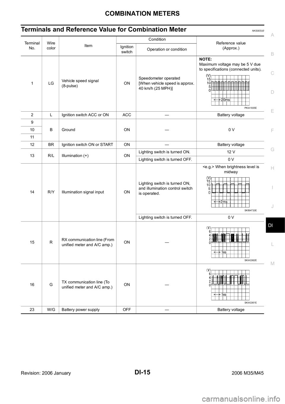
Terminals and Reference Value for Combination MeterNKS003U0
Terminal
No.Wire
colorItemCondition
Reference value
(Approx.) Ignition
switchOperation or condition
1LGVehicle speed signal
(8-pulse)ONSpeedometer operated
[When vehicle speed is approx.
40 km/h (25 MPH)]NOTE:
Maximum voltage may be 5 V due
to specifications (connected units).
2 L Ignition switch ACC or ON ACC — Battery voltage
9
B Ground ON — 0 V 10
11
12 BR Ignition switch ON or START ON — Battery voltage
13 R/L Illumination (+) ONLighting switch is turned ON. 12 V
Lighting switch is turned OFF. 0 V
14 R/Y Illumination signal input ONLighting switch is turned ON,
and illumination control switch
is operated. When brightness level is
midway
Lighting switch is turned OFF. 0 V
15 RRX communication line (From
unified meter and A/C amp.)ON —
16 GTX communication line (To
unified meter and A/C amp.)ON —
23 W/G Battery power supply OFF — Battery voltage
PKIA1935E
SKIB4733E
SKIA3362E
SKIA3361E
Page 1449 of 5621
DI-16
COMBINATION METERS
Revision: 2006 January2006 M35/M45
Terminals and Reference Value for Unified Meter and A/C Amp.NKS003U1
Te r m i n a l
No.Wire
colorItemCondition
Reference value
(Approx.) Ignition
switchOperation or condition
7RTX communication line
(To combination meter)ON —
27 GRX communication line
(From combination meter)ON —
28 LGVehicle speed signal output
(8-pulse)ONSpeedometer operated
[When vehicle speed is
approx. 40 km/h (25 MPH)]NOTE:
Maximum voltage may be 5 V due to
specifications (connected units).
41 V Ignition switch ACC or ON ACC — Battery voltage
42 P/L Fuel level sensor signal — —Refer to DI-26, "
CHECK FUEL
LEVEL SENSOR UNIT" .
53 W/G Ignition switch ON or START ON — Battery voltage
54 W/G Battery power supply OFF — Battery voltage
55 B Ground ON — 0 V
56 L CAN H — — —
58 B Fuel level sensor ground ON — 0 V
71 B Ground (power) ON — 0 V
72 P CAN L — — —
SKIA3362E
SKIA3361E
PKIA1935E