Page 5156 of 5621
STARTING SYSTEM
SC-19
C
D
E
F
G
H
I
J
L
MA
B
SC
Revision: 2006 January2006 M35/M45
VK45DE ENGINE MODELS
Removal
1. Disconnect the battery cable from the negative terminal.
2. Remove engine front and rear undercover, using power tools.
3. Remove left engine mounting insulator and left engine mounting
bracket. Refer to EM-244, "
ENGINE ASSEMBLY" .
4. Remove “B” terminal nut (1).
5. Disconnect “S” connector (2).
6. Remove the bolt (A) and the harness bracket (3).
7. Remove starter motor mounting bolts (B), using power tools.
8. Remove starter motor forward from the vehicle.
Installation
Installation is the reverse order of removal.
CAUTION:
Be sure to tighten “B” terminal nut carefully.
1. Starter motor 2. Starter motor mounting bolt 3. “S” connector
4. “B” terminal harness 5. “B” terminal nut 6. Cylinder block
: Nꞏm (kg-m, ft-lb) : Engine front
PKIB8797E
PKIB8798E
Page 5165 of 5621

SC-28
CHARGING SYSTEM
Revision: 2006 January2006 M35/M45
Trouble Diagnoses with Battery/Starting/Charging System Tester (Charging)NKS003NP
NOTE:
To ensure a complete and thorough diagnosis, the battery, starter and alternator test segments must be done
as a set from start to finish.
Before starting, perform the preliminary inspection. Refer to SC-32, "
PRELIMINARY INSPECTION" .
1. Stop the operation of the power generation voltage variable control in either of the following procedures.
After selecting “ENGINE” of “SELECT SYSTEM” using CONSULT-II, set the DUTY value of “ALTERNA-
TOR DUTY” to 0% by selecting “ALTERNATOR DUTY” of “ACTIVE TEST”. Continue “ACTIVE TEST”
until the end of inspection. (When the DUTY value is 0 or 100%, the normal power generation is per-
formed according to the characteristic of the IC regulator of the alternator.)
Turn the ignition switch OFF, and disconnect the battery current sensor connector. [However, DTC
(P1550 - P1554) of the engine might remain. After finishing the inspection, connect the battery current
sensor connector and erase the self-diagnostic results history of the engine using CONSULT-II.]
2. Turn off all loads on the vehicle electrical system.
3. Perform battery and starting system test with Battery/Starting/
Charging system tester.
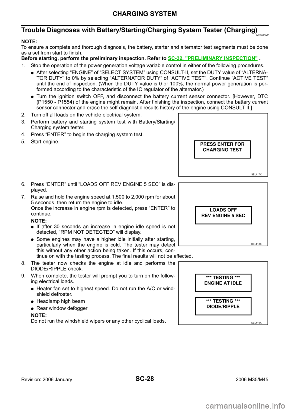
4. Press “ENTER” to begin the charging system test.
5. Start engine.
6. Press “ENTER” until “LOADS OFF REV ENGINE 5 SEC” is dis-
played.
7. Raise and hold the engine speed at 1,500 to 2,000 rpm for about
5 seconds, then return the engine to idle.
Once the increase in engine rpm is detected, press “ENTER” to
continue.
NOTE:
If after 30 seconds an increase in engine idle speed is not
detected, “RPM NOT DETECTED” will display.
Some engines may have a higher idle initially after starting,
particularly when the engine is cold. The tester may detect
this without any other action being taken. If this occurs, con-
tinue on with the testing process. The final results will not be affected.
8. The tester now checks the engine at idle and performs the
DIODE/RIPPLE check.
9. When complete, the tester will prompt you to turn on the follow-
ing electrical loads.
Heater fan set to highest speed. Do not run the A/C or wind-
shield defroster.
Headlamp high beam
Rear window defogger
NOTE:
Do not run the windshield wipers or any other cyclical loads.
SEL417X
SEL418X
SEL419X
Page 5180 of 5621

SERVICE DATA AND SPECIFICATIONS (SDS)
SC-43
C
D
E
F
G
H
I
J
L
MA
B
SC
Revision: 2006 January2006 M35/M45
SERVICE DATA AND SPECIFICATIONS (SDS)PFP:00030
BatteryNKS003NT
StarterNKS003NU
AlternatorNKS003NV
*: Adjustment range of power generation voltage variable control is 11.4 - 15.6 V. Ty p e110D26L
20 hour rate capacity [V - Ah] 12 - 75
Cold cranking current (For reference value) [A] 720
Applied modelVK45DE VQ35DE VQ35DE
2WD AWD
Ty p eM2T85771 S114-880 S114-881
MITSUBISHI
makeHITACHI make
Reduction gear type
System voltage [V] 12
No-loadTerminal voltage [V] 11
Current [A] Less than 145 Less than 90
Revolution [rpm] More than 3,300 More than 2,880
Minimum diameter of commutator [mm (in)] 31.4 (1.236) 28.0 (1.102)
Minimum length of brush [mm (in)] 11.0 (0.433) 10.5 (0.413)
Brush spring tension [N (kg, lb)]26.7 - 36.1
(2.72 - 3.68,
6.80 - 8.12)16.2 (1.65, 3.6)
Clearance between bearing metal and armature shaft [mm (in)] Less than 0.2 (0.008)
Clearance between pinion front edge and pinion stopper [mm (in)]0.5 - 2.0
(0.020 - 0.079)0.3 - 2.5 (0.012 - 0.098)
Applied model VK45DE VQ35DE
Ty p eA3TJ0591 A3TJ0691
MITSUBISHI make
Nominal rating [V - A] 12 -150
Ground polarityNegative
Minimum revolution under no-load (When 13.5 V is
applied)[rpm] Less than 1,300
Hot output current (When 13.5 V is applied) [A/rpm]More than 35/1,300
More than 105/2,500
More than 136/5,000
Regulated output voltage [V] 14.1 - 14.7 *
Minimum length of brush [mm (in)] More than 5.00 (0.197)
Brush spring pressure [N (g, oz)] 4.1 - 5.3 (418 - 540, 14.8 - 19.1)
Slip ring minimum outer diameter [mm (in)] More than 22.1 (0.870)
Rotor (Field coil) resistance [
] 1.6 - 2.0
Page 5219 of 5621

SE-38
AUTOMATIC DRIVE POSITIONER
Revision: 2006 January2006 M35/M45
ACTIVE TEST
CAUTION:
During vehicle driving, do not perform active test.
NOTE:
If active test is performed, reset seat memory and key fob interlock drive positioner after performing work.
DISPLAY ITEM LIST
WORK SUPPORT
The seat slide amount at entry/exit operation setting can be changed by CONSULT-II. Refer to SE-16, "SET-
TING CHANGE FUNCTION" .
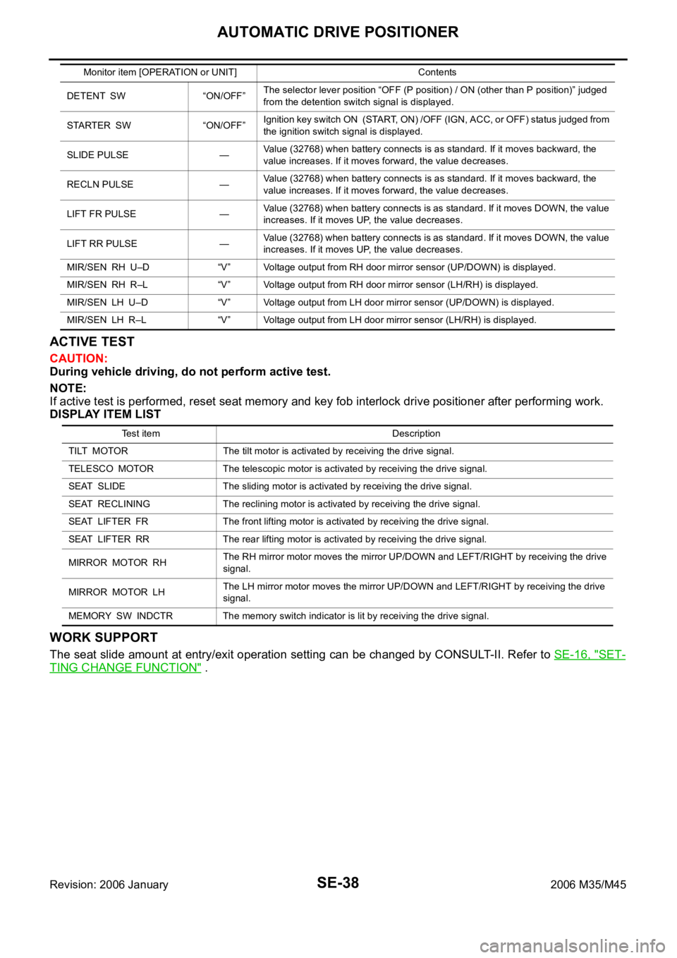
DETENT SW “ON/OFF”The selector lever position “OFF (P position) / ON (other than P position)” judged
from the detention switch signal is displayed.
STARTER SW “ON/OFF”Ignition key switch ON (START, ON) /OFF (IGN, ACC, or OFF) status judged from
the ignition switch signal is displayed.
SLIDE PULSE —Value (32768) when battery connects is as standard. If it moves backward, the
value increases. If it moves forward, the value decreases.
RECLN PULSE —Value (32768) when battery connects is as standard. If it moves backward, the
value increases. If it moves forward, the value decreases.
LIFT FR PULSE —Value (32768) when battery connects is as standard. If it moves DOWN, the value
increases. If it moves UP, the value decreases.
LIFT RR PULSE —Value (32768) when battery connects is as standard. If it moves DOWN, the value
increases. If it moves UP, the value decreases.
MIR/SEN RH U–D “V” Voltage output from RH door mirror sensor (UP/DOWN) is displayed.
MIR/SEN RH R–L “V” Voltage output from RH door mirror sensor (LH/RH) is displayed.
MIR/SEN LH U–D “V” Voltage output from LH door mirror sensor (UP/DOWN) is displayed.
MIR/SEN LH R–L “V” Voltage output from LH door mirror sensor (LH/RH) is displayed. Monitor item [OPERATION or UNIT] Contents
Test item Description
TILT MOTOR The tilt motor is activated by receiving the drive signal.
TELESCO MOTOR The telescopic motor is activated by receiving the drive signal.
SEAT SLIDE The sliding motor is activated by receiving the drive signal.
SEAT RECLINING The reclining motor is activated by receiving the drive signal.
SEAT LIFTER FR The front lifting motor is activated by receiving the drive signal.
SEAT LIFTER RR The rear lifting motor is activated by receiving the drive signal.
MIRROR MOTOR RHThe RH mirror motor moves the mirror UP/DOWN and LEFT/RIGHT by receiving the drive
signal.
MIRROR MOTOR LHThe LH mirror motor moves the mirror UP/DOWN and LEFT/RIGHT by receiving the drive
signal.
MEMORY SW INDCTR The memory switch indicator is lit by receiving the drive signal.