Page 4134 of 4462

SC-28
CHARGING SYSTEM
Revision: 2006 December 2006 FX35/FX45
Alternator Pulley Inspection
Perform the following.
�Make sure that alternator pulley does not rattle.
�Make sure that alternator pulley nut is tight.
Installation
Installation is the reverse order of removal.
�Install alternator, and check tension of belt. Refer to EM-174, "Checking Drive Belts" .
CAUTION:
Be sure to tighten “B” terminal nut carefully.
VQ35DE ENGINE MODELS
Removal
1. Disconnect the battery cable from the negative terminal.
2. Remove engine front undercover, using power tools.
3. Remove alternator and power steering oil pump belt. Refer to EM-16, "
Removal and Installation" .
4. Disconnect alternator connector.
5. Remove “B” terminal nut.
6. Remove harness clip and water hose bracket from alternator. Alternator pulley nut:
: 73.5 N·m (7.5 kg-m, 54 ft-lb)
1. B terminal nut 2. B terminal harness 3. Alternator connector
4. Alternator mounting bolt 5. Alternator stay mounting bolt 6. Alternator stay
7. Alternator
: N·m (kg-m, ft-lb) : Engine front
PKIB8815E
PKIA2358E
Page 4135 of 4462
CHARGING SYSTEM SC-29
C
D E
F
G H
I
J
L
M A
B
SC
Revision: 2006 December 2006 FX35/FX45
7. Remove oil pressure switch harness clip from alternator stay. (2WD)
8. Disconnect oil pressure switch connector. (2WD)
9. Remove alternator stay mounting bolts and alternator stay, using power tools.
10. Remove alternator mounting bolt, using power tools.
11. Remove alternator assembly downward from the vehicle.
Alternator Pulley Inspection
Perform the following.
�Make sure that alternator pulley does not rattle.
�Make sure that alternator pulley nut is tight.
Installation
Installation is the reverse order of removal.
�Install alternator, and check tension of belt. Refer to EM-15, "Checking Drive Belts" .
CAUTION:
Be sure to tighten “B” terminal nut carefully.
PKIA1923E
Alternator pulley nut:
: 118 N·m (12.0 kg-m, 87 ft-lb)
Page 4138 of 4462

Revision: 2006 December 2006 FX35/FX45
SERVICE DATA AND SPECIFICATIONS (SDS)PFP:00030
BatteryNKS002V0
StarterNKS002V1
AlternatorNKS002V2
Ty p e 110D26L
Cap")
SC-32
SERVICE DATA AND SPECIFICATIONS (SDS)
Revision: 2006 December 2006 FX35/FX45
SERVICE DATA AND SPECIFICATIONS (SDS)PFP:00030
BatteryNKS002V0
StarterNKS002V1
AlternatorNKS002V2
Ty p e 110D26L
Capacity V - AH 12 - 64
Cold cranking current (For reference value) A 720
Applied model VK45DE VQ35DE (2WD) VQ35DE (AWD)
Ty p e M2T85075 S114-880 S114-881
MITSUBISHI make HITACHI make Reduction gear type
System voltage V 12
No-load Terminal voltage V 11
Current A Less than 145 Less than 90
Revolution rpm More than 3,300 More than 2,880
Minimum diameter of commutator mm (in) 31.4 (1.236) 28.0 (1.102)
Minimum length of brush mm (in) 11.0 (0.433) 10.5 (0.413)
Brush spring tension N (kg, lb) 26.7 - 36.1
(2.72 - 3.68, 6.80 - 8.12) 16.2 (1.65, 3.6)
Clearance between bearing metal and armature shaft mm (in) Less than 0.2 (0.008)
Clearance between pinion front edge and pinion stopper mm (in) 0.5 - 2.0
(0.020 - 0.079) 0.3 - 2.5 (0.012 - 0.098)
Applied model VK45DE VQ35DE
Type LR1110 - 716V A3TG0191
HITACHI make MITSUBISHI make
Nominal rating V - A 12 - 110
Ground polarity Negative
Minimum revolution under no-load (When 13.5 V is applied) rpm Less than 1,100 Less than 1,000
Hot output current (When 13.5 V is applied) A/rpm More than 70/1,800
More than 91/2,500
More than 110/5,000 More than 37/1,300
More than 92/2,500
More than 103/5,000
Regulated output voltage V 14.1 - 14.7
Minimum length of brush mm (in) More than 6.00 (0.236) More than 5.00 (0.197)
Brush spring pressure N (g, oz) 1.00 - 3.43
(102 - 350, 3.60 - 12.34) 4.8 - 6.0
(490 - 612, 17.28 - 21.60)
Slip ring minimum outer diameter mm (in) More than 26.0 (1.024) More than 22.1 (0.870)
Rotor (Field coil) resistance Ω2.31 1.7 - 2.1
Page 4141 of 4462
 “AIR BAG” and “SEAT
BELT")
PRECAUTIONS SE-3
C
D E
F
G H
J
K L
M A
B
SE
Revision: 2006 December 2006 FX35/FX45
PRECAUTIONSPFP:00001
Precautions for Supplemental Restraint System (SRS) “AIR BAG” and “SEAT
BELT PRE-TENSIONER”
NIS001UH
The Supplemental Restraint System such as “AIR BAG” and “SEAT BELT PRE-TENSIONER”, used along
with a front seat belt, helps to reduce the risk or severity of injury to the driver and front passenger for certain
types of collision. This system includes seat belt switch inputs and dual stage front air bag modules. The SRS
system uses the seat belt switches to determine the front air bag deployment, and may only deploy one front
air bag, depending on the severity of a collision and whether the front occupants are belted or unbelted.
Information necessary to service the system safely is included in the SRS and SB section of this Service Man-
ual.
WARNING:
�To avoid rendering the SRS inoperative, which could increase the risk of personal injury or death
in the event of a collision which would result in air bag inflation, all maintenance must be per-
formed by an authorized NISSAN/INFINITI dealer.
�Improper maintenance, including incorrect removal and installation of the SRS, can lead to per-
sonal injury caused by unintentional activation of the system. For removal of Spiral Cable and Air
Bag Module, see the SRS section.
�Do not use electrical test equipment on any circuit related to the SRS unless instructed to in this
Service Manual. SRS wiring harnesses can be identified by yellow and/or orange harnesses or
harness connectors.
Service NoticeNIS001UI
�When removing or installing various parts, place a cloth or padding onto the vehicle body to prevent
scratches.
�Handle trim, molding, instruments, grille, etc. carefully during removing or installing. Be careful not to oil or
damage them.
�Apply sealing compound where necessary when installing parts.
�When applying sealing compound, be careful that the sealing compound does not protrude from parts.
�When replacing any metal parts (for example body outer panel, members, etc.), be sure to take rust pre-
vention measures.
Page 4287 of 4462
DRIVER AIR BAG MODULE SRS-39
C
D E
F
G
I
J
K L
M A
B
SRS
Revision: 2006 December 2006 FX35/FX45
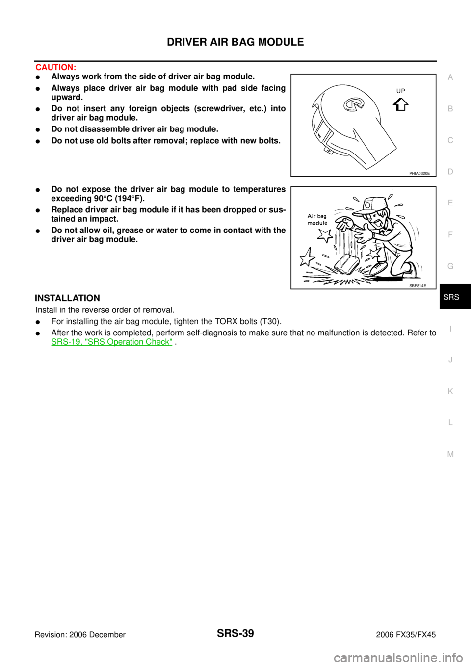
CAUTION:
�Always work from the side of driver air bag module.
�Always place driver air bag module with pad side facing
upward.
�Do not insert any foreign objects (screwdriver, etc.) into
driver air bag module.
�Do not disassemble driver air bag module.
�Do not use old bolts after removal; replace with new bolts.
�Do not expose the driver air bag module to temperatures
exceeding 90 °C (194 °F).
�Replace driver air bag module if it has been dropped or sus-
tained an impact.
�Do not allow oil, grease or water to come in contact with the
driver air bag module.
INSTALLATION
Install in the reverse order of removal.
�For installing the air bag module, tighten the TORX bolts (T30).
�After the work is completed, perform self-diagnosis to make sure that no malfunction is detected. Refer to
SRS-19, "
SRS Operation Check" .
PHIA0320E
SBF814E
Page 4291 of 4462
FRONT PASSENGER AIR BAG MODULE SRS-43
C
D E
F
G
I
J
K L
M A
B
SRS
Revision: 2006 December 2006 FX35/FX45
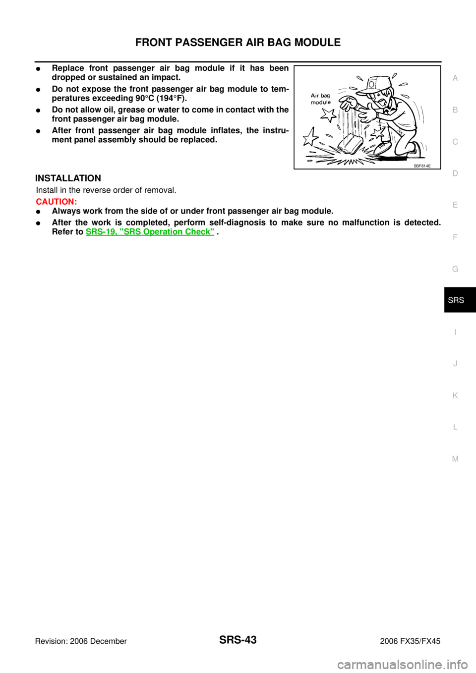
�Replace front passenger air bag module if it has been
dropped or sustained an impact.
�Do not expose the front passenger air bag module to tem-
peratures exceeding 90 °C (194 °F).
�Do not allow oil, grease or water to come in contact with the
front passenger air bag module.
�After front passenger air bag module inflates, the instru-
ment panel assembly should be replaced.
INSTALLATION
Install in the reverse order of removal.
CAUTION:
�Always work from the side of or under front passenger air bag module.
�After the work is completed, perform self-diagnosis to make sure no malfunction is detected.
Refer to SRS-19, "
SRS Operation Check" .
SBF814E
Page 4292 of 4462

SRS-44
SIDE CURTAIN AIR BAG MODULE
Revision: 2006 December 2006 FX35/FX45
SIDE CURTAIN AIR BAG MODULEPFP:985P0
Removal and InstallationNHS0007O
REMOVAL
CAUTION:
�Before servicing SRS, turn ignition switch OFF, disconnect both battery cables and wait at least 3
minutes.
�Always work from the side of the side curtain air bag module.
1. Remove headlining. Refer to EI-42, "
Removal and Installation" .
2. Disconnect side curtain air bag connector.
3. Remove side curtain air bag module fixing bolts, and remove the side curtain air bag module.
CAUTION:
�Always place the side curtain air bag module with the warn-
ing label facing upward.
�Do not disassemble side curtain air bag module.
�Do not insert any foreign objects (screwdriver, etc.) into air
bag module connector.
�Replace side curtain air bag module if it has been dropped
or sustained an impact.
�Do not expose the air bag module to temperatures exceed-
ing 90 °C (194 °F).
�Do not allow oil, grease or water to come in contact with the
side curtain air bag module.
1. Side curtain air bag Inflator 2. Side curtain air bag 3. Bolt
4. Assist grip bracket 5. Bolt (There is no torque control)
PHIA0656E
PHIA0317E
SBF814E
Page 4304 of 4462

TF-2Revision: 2006 December 2006 FX35/FX45 Started .................................................................
... 35
DIAGNOSTIC PROCEDURE ........................... ... 35
Vehicle Does Not Enter AWD Mode Even Though
AWD Warning Lamp Turned to OFF .................... ... 36
DIAGNOSTIC PROCEDURE ........................... ... 36
While Driving, AWD Warning Lamp Flashes Rapidly
(When Flashing in Approx. 1 Minute and Then Turn-
ing OFF) .............................................................. ... 37
While Driving, AWD Warning Lamp Flashes Slowly
(When Continuing to Flash until Turning Ignition
Switch OFF) ......................................................... ... 37
DIAGNOSTIC PROCEDURE ........................... ... 37
AWD CONTROL UNIT ........................................... ... 39
Removal and Installation ..................................... ... 39
REMOVAL ........................................................ ... 39
INSTALLATION ................................................. ... 39
FRONT OIL SEAL .................................................. ... 40
Removal and Installation ..................................... ... 40
REMOVAL ........................................................ ... 40
INSTALLATION ................................................. ... 40 REAR OIL SEAL ....................................................
... 41
Removal and Installation ...................................... ... 41
REMOVAL ......................................................... ... 41
INSTALLATION ................................................. ... 42
AIR BREATHER HOSE .......................................... ... 43
Removal and Installation ...................................... ... 43
TRANSFER ASSEMBLY ........................................ ... 44
Removal and Installation ...................................... ... 44
REMOVAL ......................................................... ... 44
INSTALLATION ................................................. ... 44
Disassembly and Assembly ................................. ... 45
COMPONENTS ................................................ ... 45
DISASSEMBLY ................................................. ... 46
INSPECTION .................................................... ... 51
ASSEMBLY ....................................................... ... 52
SERVICE DATA AND SPECIFICATIONS (SDS) ... ... 59
General Specifications ......................................... ... 59

8. Disconnect oil pressure")