Page 4307 of 4462

PREPARATION TF-5
C E F
G H
I
J
K L
M A
B
TF
Revision: 2006 December 2006 FX35/FX45
PREPARATIONPFP:00002
Special Service ToolsNDS0009P
The actual shapes of Kent-Moore tools may differ from those of special service tools illustrated here. Tool number
(Kent-Moore No.)
Tool name Description
ST27862000
(—)
Drift
a: 62.5 mm (2.461 in) dia.
b: 42 mm (1.65 in) dia.
�Installing front oil seal
KV381054S0
(J-34286)
Puller
�Removing rear oil seal
ST30720000
(J-25405)
Drift
a: 77 mm (3.03 in) dia.
b: 55.5 mm (2.185 in) dia.
�Installing rear oil seal
�Installing mainshaft oil seal
KV40104830
(—)
Drift
a: 70 mm (2.76 in) dia.
b: 63.5 mm (2.500 in) dia.
�Installing rear oil seal
KV38100300
(J-25523)
Drift
a: 54 mm (2.13 in) dia.
b: 46 mm (1.81 in) dia.
c: 32 mm (1.26 in) dia.
�Removing mainshaft bearing
ST33052000
(—)
Drift
a: 28 mm (1.10 in) dia.
b: 22 mm (0.87 in) dia.
�Removing mainshaft assembly
ST30611000
(J-25742-1)
Drift bar
a: 350 mm (1.10 in)
b: 25 mm (1.10 in) dia.
c: M12 × 1.5P
�Removing rear bearing
ZZA0194D
ZZA0601D
ZZA0811D
ZZA1003D
ZZA1046D
ZZA1000D
NT663
Page 4310 of 4462
TF-8
NOISE, VIBRATION AND HARSHNESS (NVH) TROUBLESHOOTING
Revision: 2006 December 2006 FX35/FX45
NOISE, VIBRATION AND HARSHNESS (NVH) TROUBLESHOOTINGPFP:00003
NVH Troubleshooting ChartNDS0009R
Use the chart below to help you find the cause of the symptom. The numbers indicate the order of the inspec-
tion. If necessary, repair or replace these parts.
Reference pageTF-9TF-45TF-45TF-51TF-51TF-51
SUSPECTED PARTS
(Possible cause)
TRANSFER FLUID (Level low)
TRANSFER FLUID (Wrong)
TRANSFER FLUID (Level too high)
LIQUID GASKET (Damaged)
OIL SEAL (Worn or damaged)
GEAR (Worn or damaged)
BEARING (Worn or damaged)
TRANSFER CASE (Damaged)
Symptom Noise 1 2 3 3 3
Transfer fluid leakage 4 1 2 2 3
Page 4342 of 4462
TF-40
FRONT OIL SEAL
Revision: 2006 December 2006 FX35/FX45
FRONT OIL SEALPFP:38189
Removal and InstallationNDS000AK
REMOVAL
1. Remove the drain plug to drain the transfer fluid. Refer to TF-9, "Replacement" .
2. Remove the front propeller shaft. Refer to PR-4, "
FRONT PROPELLER SHAFT" .
3. Remove front oil seal using a flat-bladed screwdriver. CAUTION:
Be careful not to damage the front case and front drive
shaft.
INSTALLATION
1. Apply ATF to front oil seal, install it with a drift until the end face of front case.
CAUTION:
�Do not reuse front oil seal.
�When installing, do not incline front oil seal.
2. Install front propeller shaft. Refer to PR-4, "
FRONT PROPEL-
LER SHAFT" .
3. Install transfer fluid, check fluid level and for fluid leakage. Refer to TF-9, "
Inspection" .
SDIA1782E
Tool number : ST27862000 ( — )
SDIA1783E
Page 4343 of 4462
REAR OIL SEAL TF-41
C E F
G H
I
J
K L
M A
B
TF
Revision: 2006 December 2006 FX35/FX45
REAR OIL SEALPFP:33140
Removal and InstallationNDS000AL
REMOVAL
1. Remove the rear propeller shaft. Refer to PR-7, "REAR PROPELLER SHAFT" .
2. Remove self-lock nut of companion flange using the flange wrench.
3. Put matching mark on the end of the mainshaft. The mark should be in line with the mark on the companion flange.
CAUTION:
For matching mark, use paint. Do not damage mainshaft.
4. Remove the companion flange using a puller. CAUTION:
Be careful not to damage the companion flange.
5. Remove the rear oil seal using a puller. CAUTION:
Be careful not to damage the rear case.
SDIA2454E
SDIA2378E
SDIA1785E
Tool number : KV381054S0 (J-34286)
SDIA1786E
Page 4344 of 4462
TF-42
REAR OIL SEAL
Revision: 2006 December 2006 FX35/FX45
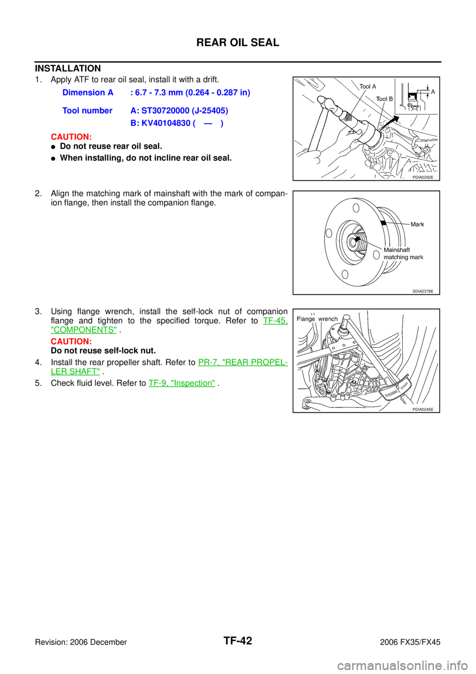
INSTALLATION
1. Apply ATF to rear oil seal, install it with a drift. CAUTION:
�Do not reuse rear oil seal.
�When installing, do not incline rear oil seal.
2. Align the matching mark of mainshaft with the mark of compan- ion flange, then install the companion flange.
3. Using flange wrench, install the self-lock nut of companion flange and tighten to the specified torque. Refer to TF-45,
"COMPONENTS" .
CAUTION:
Do not reuse self-lock nut.
4. Install the rear propeller shaft. Refer to PR-7, "
REAR PROPEL-
LER SHAFT" .
5. Check fluid level. Refer to TF-9, "
Inspection" .
Dimension A : 6.7 - 7.3 mm (0.264 - 0.287 in)
Tool number A: ST30720000 (J-25405) B: KV40104830 ( — )
PDIA0292E
SDIA2378E
PDIA0245E
Page 4347 of 4462
TRANSFER ASSEMBLY TF-45
C E F
G H
I
J
K L
M A
B
TF
Revision: 2006 December 2006 FX35/FX45
Disassembly and AssemblyNDS000AO
COMPONENTS
1. Drive chain 2. Front drive shaft rear bearing 3. Front drive shaft
4. Front drive shaft front bearing 5. Sprocket 6. Mainshaft
7. Needle bearing 8. Snap ring 9. Mainshaft bearing
10. Front case 11. Front oil seal 12. Mainshaft oil seal
13. Oil cover 14. Temperature sensor 15. Electric controlled coupling
16. Spacer 17. Snap ring 18. O-ring
19. Oil gutter 20. Drain plug 21. Baffle plate
22. Rear bearing 23. Snap ring 24. Spacer
25. Rear oil seal 26. Companion flange 27. Self-lock nut
28. Breather tube 29. Rear case 30. Harness bracket
31. Retainer 32. Filler plug 33. Gasket
PDIA0244E
Page 4348 of 4462
TF-46
TRANSFER ASSEMBLY
Revision: 2006 December 2006 FX35/FX45
DISASSEMBLY
Front Case and Rear Case
1. Remove drain plug and filler plug.
2. Remove mainshaft oil seal from front case, using a flat-bladed screwdriver.
CAUTION:
Be careful not to damage the front case and mainshaft.
3. Remove front oil seal from front case, using a flat-bladed screw- driver.
CAUTION:
Be careful not to damage the front case and front drive
shaft.
4. Remove self-lock nut.
5. Put a matching mark on the end of mainshaft. The mark should be in line with the mark on the companion flange.
CAUTION:
For matching mark, use paint. Do not damage mainshaft.
6. Remove companion flange, using a puller. CAUTION:
Be careful not to damage the companion flange.
PDIA0253E
PDIA0255E
SDIA2378E
PDIA0258E
Page 4349 of 4462
TRANSFER ASSEMBLY TF-47
C E F
G H
I
J
K L
M A
B
TF
Revision: 2006 December 2006 FX35/FX45
7. Remove rear oil seal from rear case, using a puller. CAUTION:
Be careful not to damage the rear case.
8. Remove spacer from mainshaft.
9. Remove front case and rear case fixing bolts, then remove har- ness bracket.
10. Separate front case and rear case. Then, remove front case by levering it up with a tire lever or the like.
CAUTION:
Be careful not to damage the mating surface. Tool number : KV381054S0 (J-34286)
PDIA0259E
PDIA0260E
Bolts symbol Quantity
Bolt length “ ” mm (in)
A 11 42 (1.65)
B 1 162 (6.38)
C 1 97 (3.82)
TORX bolts 1 40 (1.57)
PDIA0251E
SDIA2460E
 TROUBLESHOOTING
Revision: 2006 December 2006 FX35/FX45
NOISE, VIBRATION AND HARSHNESS (NVH) TROUBLESHOOTINGPFP:00003
NVH Troubleshooting ChartNDS0009R
Use the")