Page 3015 of 4462
![INFINITI FX35 2006 Service Manual CAMSHAFT EM-221
[VK45DE]
C
D E
F
G H
I
J
K L
M A
EM
Revision: 2006 December 2006 FX35/FX45
4. Tighten camshaft bracket bolts in the following steps, in numeri- cal order as shown in the f](/manual-img/42/57019/w960_57019-3014.png "INFINITI FX35 2006 Service Manual CAMSHAFT EM-221
[VK45DE]
C
D E
F
G H
I
J
K L
M A
EM
Revision: 2006 December 2006 FX35/FX45
4. Tighten camshaft bracket bolts in the following steps, in numeri- cal order as shown in the f")
CAMSHAFT EM-221
[VK45DE]
C
D E
F
G H
I
J
K L
M A
EM
Revision: 2006 December 2006 FX35/FX45
4. Tighten camshaft bracket bolts in the following steps, in numeri- cal order as shown in the figure.
a. Tighten No. 9 to 12 in numerical order as shown.
b. Tighten No. 1 to 8 in numerical order as shown.
c. Tighten No. 13 to 14 in numerical order as shown. (Left bank only)
d. Tighten all bolts in numerical order as shown.
e. Tighten No. 1 to 12 in numerical order as shown.
f. Tighten No. 13 to 14 in numerical order as shown. (Left bank only)
CAUTION:
After tightening mounting bolts of camshaft brackets, be sure to wipe off excessive liquid gasket
from the parts listed below.
�Mating surface of rocker cover
�Mating surface of front cover
5. Install camshaft sprockets.
�Install by checking with identification mark on surface.
�Install camshaft sprocket (EXH) by selectively using the
groove of dowel pin according to the bank. (Common part
used for both banks.)
�Lock the hexagonal part of camshaft in the same way as for
removal, and tighten mounting bolts.
6. Check and adjust the valve clearance. Refer to EM-222, "
Valve Clearance" .
7. Install in the reverse order of removal after this step.
INSPECTION AFTER INSTALLATION
Inspection of Camshaft Sprocket (INT) Oil Groove
CAUTION:
�Perform this inspection only when DTC P0011 and/or P0021 are detected in self-diagnostic results
of CONSULT-II and it is directed according to inspection procedure of EC section. Refer to EC-748,
"TROUBLE DIAGNOSIS" .
�Check when the engine is cold so as to prevent burns from any splashing engine oil.
1. Check the engine oil level. Refer to LU-25, "
ENGINE OIL" .
2. Perform the following procedure so as to prevent the engine from being unintentionally started while checking.
a. Release fuel pressure. Refer to EC-746, "
FUEL PRESSURE RELEASE" .
b. Disconnect ignition coil and injector harness connectors.
3. Remove intake valve timing control solenoid valve. Refer to EM-203, "
TIMING CHAIN" .
: 1.96 N·m (0.2 kg-m, 1 ft-lb)
: 1.96 N·m (0.2 kg-m, 1 ft-lb)
: 1.96 N·m (0.2 kg-m, 1 ft-lb)
: 5.88 N·m (0.6 kg-m, 4 ft-lb)
: 10.41 N·m (1.1 kg-m, 8 ft-lb)
: 31.35 N·m (3.2 kg-m, 23 ft-lb)
PBIC0031E
PBIC2345E
Page 3021 of 4462
![INFINITI FX35 2006 Service Manual CAMSHAFT EM-227
[VK45DE]
C
D E
F
G H
I
J
K L
M A
EM
Revision: 2006 December 2006 FX35/FX45
�Thickness of new adjusting shim can be identified by stamp
marks on the reverse side (inside th](/manual-img/42/57019/w960_57019-3020.png "INFINITI FX35 2006 Service Manual CAMSHAFT EM-227
[VK45DE]
C
D E
F
G H
I
J
K L
M A
EM
Revision: 2006 December 2006 FX35/FX45
�Thickness of new adjusting shim can be identified by stamp
marks on the reverse side (inside th")
CAMSHAFT EM-227
[VK45DE]
C
D E
F
G H
I
J
K L
M A
EM
Revision: 2006 December 2006 FX35/FX45
�Thickness of new adjusting shim can be identified by stamp
marks on the reverse side (inside the cylinder).
8. Install new adjusting shim using suitable tool.
�Install with the surface on which the thickness is
stamped facing down.
9. Remove lifter stopper as follows:
a. Except exhaust side of No. 7 and 8 cylinder;
i. Perform same procedure for removal, place camshaft pliers (SST).
ii. Remove lifter stopper (SST).
iii. Remove camshaft pliers.
b. Exhaust side of No. 7 and 8 cylinder.
�Rotate crankshaft slowly 180 degrees clockwise. then remove lifter stopper.
10. Manually turn crankshaft pulley a few turns.
11. Make sure that the valve clearance is within the standard. Refer to EM-222, "
INSPECTION" .
12. Install all removed parts in the reverse order of removal. Refer to EM-219, "
INSTALLATION" .
13. Warm up the engine, and check for unusual noise and vibration.
SEM873E
PBIC1568E
PBIC1569E
Page 3022 of 4462
![INFINITI FX35 2006 Service Manual EM-228
[VK45DE]
OIL SEAL
Revision: 2006 December 2006 FX35/FX45
OIL SEALPFP:00100
Removal and Installation of Valve Oil SealNBS003IG
REMOVAL
1. Remove engine assembly from vehicle. Refer to EM-243, "](/manual-img/42/57019/w960_57019-3021.png "INFINITI FX35 2006 Service Manual EM-228
[VK45DE]
OIL SEAL
Revision: 2006 December 2006 FX35/FX45
OIL SEALPFP:00100
Removal and Installation of Valve Oil SealNBS003IG
REMOVAL
1. Remove engine assembly from vehicle. Refer to EM-243, \"")
EM-228
[VK45DE]
OIL SEAL
Revision: 2006 December 2006 FX35/FX45
OIL SEALPFP:00100
Removal and Installation of Valve Oil SealNBS003IG
REMOVAL
1. Remove engine assembly from vehicle. Refer to EM-243, "ENGINE ASSEMBLY" .
2. Remove camshaft relating to valve oil seal to be removed. Refer to EM-215, "
CAMSHAFT" .
3. Remove adjusting shims and valve lifters. Refer to EM-215, "
CAMSHAFT" .
�Identify installation positions, and store them without mixing them up.
4. Turn crankshaft until the cylinder requiring new oil seals is at TDC. This will prevent valve from dropping into cylinder.
5. Remove valve collet.
�Compress valve spring with valve spring compressor, attach-
ment and adapter (SST). Remove valve collet with magnetic
hand.
CAUTION:
When working, take care not to damage valve lifter holes.
6. Remove valve spring retainer and valve spring (with valve spring seat). CAUTION:
Do not remove valve spring seat from valve spring.
7. Remove valve oil seal using valve oil seal puller (SST).
INSTALLATION
1. Apply new engine oil on new valve oil seal joint and seal lip.
2. Install valve oil seal.
�Install with valve oil seal drift (SST) to match dimension in the
figure.
3. Install in the reverse order of removal.
PBIC2360E
PBIC0072E
PBIC0073E
Page 3023 of 4462
![INFINITI FX35 2006 Service Manual OIL SEAL EM-229
[VK45DE]
C
D E
F
G H
I
J
K L
M A
EM
Revision: 2006 December 2006 FX35/FX45
Removal and Installation of Front Oil SealNBS003IH
REMOVAL
1. Remove the following parts:
�Front](/manual-img/42/57019/w960_57019-3022.png "INFINITI FX35 2006 Service Manual OIL SEAL EM-229
[VK45DE]
C
D E
F
G H
I
J
K L
M A
EM
Revision: 2006 December 2006 FX35/FX45
Removal and Installation of Front Oil SealNBS003IH
REMOVAL
1. Remove the following parts:
�Front")
OIL SEAL EM-229
[VK45DE]
C
D E
F
G H
I
J
K L
M A
EM
Revision: 2006 December 2006 FX35/FX45
Removal and Installation of Front Oil SealNBS003IH
REMOVAL
1. Remove the following parts:
�Front engine undercover
�Radiator; Refer to CO-41, "RADIATOR"
�Drive belt; Refer to EM-174, "DRIVE BELTS" .
�Cooling fan; Refer to CO-49, "COOLING FAN" .
�Rear plate cover; Refer to EM-187, "OIL PAN AND OIL STRAINER" .
2. Remove crankshaft pulley as follows:
a. Set ring gear stopper (SST).
b. Loosen crankshaft pulley bolt, and then pull crankshaft pulley with both hands to remove it.
CAUTION:
�Do not remove crankshaft pulley bolt. Keep loosened
crankshaft pulley bolt in place to protect removed crank-
shaft pulley from dropping.
�Do not remove balance weight (inner hexagon bolt) at the
front of crankshaft pulley.
3. Remove front oil seal using suitable tool. CAUTION:
Be careful not to damage front cover and oil pump drive
spacer.
INSTALLATION
1. Apply new engine oil to both oil seal lip and dust seal lip of new front oil seal.
2. Install front oil seal.
PBIC1656E
SBIA0358E
SBIA0359E
Page 3024 of 4462
![INFINITI FX35 2006 Service Manual EM-230
[VK45DE]
OIL SEAL
Revision: 2006 December 2006 FX35/FX45
�Install front oil seal so that each seal lip is oriented as shown
in the figure.
�Using front oil seal drift, press fit until the heig](/manual-img/42/57019/w960_57019-3023.png "INFINITI FX35 2006 Service Manual EM-230
[VK45DE]
OIL SEAL
Revision: 2006 December 2006 FX35/FX45
�Install front oil seal so that each seal lip is oriented as shown
in the figure.
�Using front oil seal drift, press fit until the heig")
EM-230
[VK45DE]
OIL SEAL
Revision: 2006 December 2006 FX35/FX45
�Install front oil seal so that each seal lip is oriented as shown
in the figure.
�Using front oil seal drift, press fit until the height of front oil
seal is level with the mounting surface.
�Make sure the garter spring is in position and seal lips not
inverted.
CAUTION:
�Be careful not to damage front cover and oil pump drive
spacer.
�Press fit straight and avoid causing burrs or tilting oil seal.
3. Install in the reverse order of removal.
Removal and Installation of Rear Oil SealNBS003II
REMOVAL
1. Remove transmission (with transfer) assembly. Refer to AT- 2 6 6 , "TRANSMISSION ASSEMBLY" .
a. Remove drive plate. Refer to EM-248, "
CYLINDER BLOCK" .
b. Remove engine rear plate. Refer to EM-248, "
CYLINDER BLOCK" .
2. Remove rear oil seal using suitable tool. CAUTION:
Be careful not to damage crankshaft and oil seal retainer
surface.
INSTALLATION
1. Apply new engine oil to both oil seal lip and dust seal lip of new rear oil seal.
2. Install rear oil seal.
�Install rear oil seal so that each seal lip is oriented as shown
in the figure.
SEM715A
Front oil seal drift
Outer diameter : 56 mm (2.20 in)
Inner diameter : 49 mm (1.93 in)
SBIA0359E
SBIA0360E
SEM715A
Page 3025 of 4462
OIL SEAL EM-231
[VK45DE]
C
D E
F
G H
I
J
K L
M A
EM
Revision: 2006 December 2006 FX35/FX45
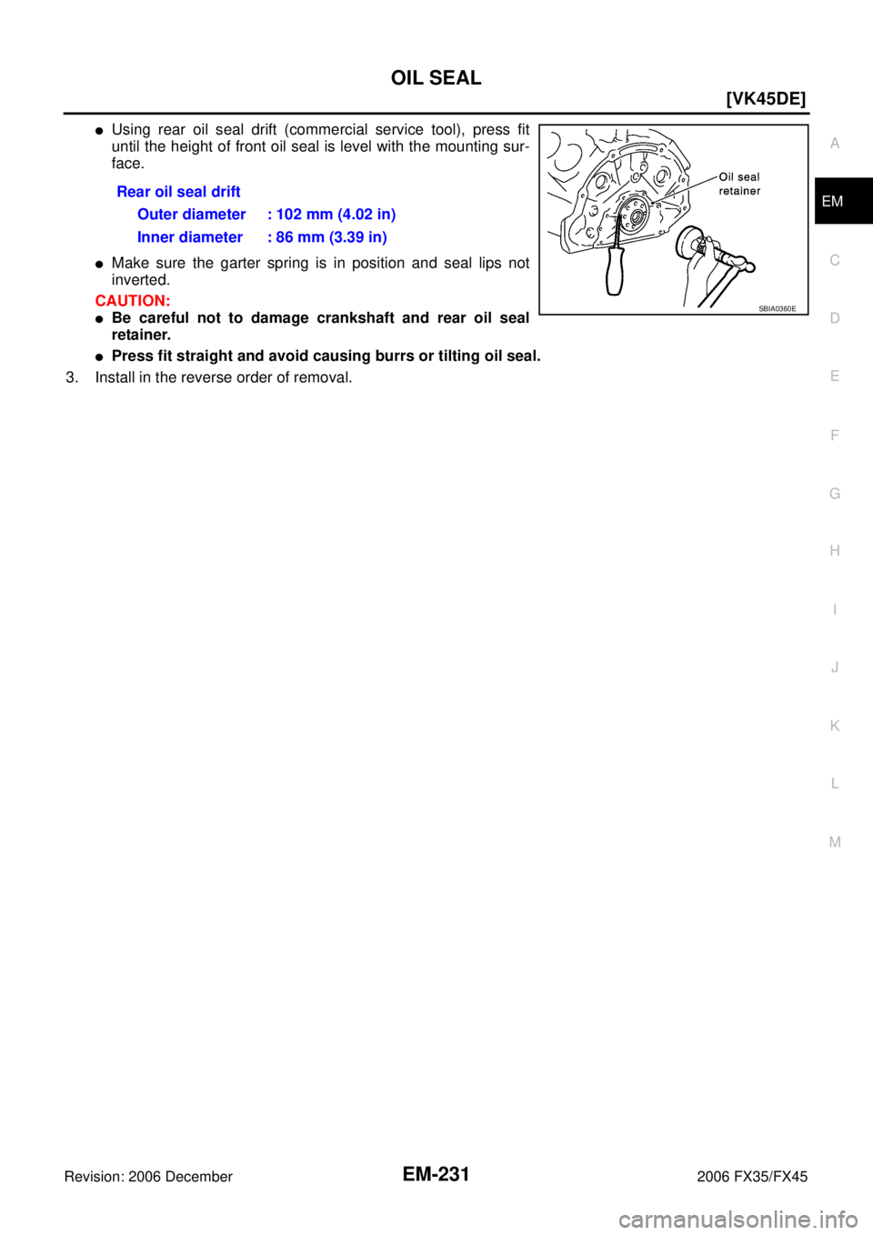
�Using rear oil seal drift (commercial service tool), press fit
until the height of front oil seal is level with the mounting sur-
face.
�Make sure the garter spring is in position and seal lips not
inverted.
CAUTION:
�Be careful not to damage crankshaft and rear oil seal
retainer.
�Press fit straight and avoid causing burrs or tilting oil seal.
3. Install in the reverse order of removal. Rear oil seal drift
Outer diameter : 102 mm (4.02 in)
Inner diameter : 86 mm (3.39 in)
SBIA0360E
Page 3026 of 4462
![INFINITI FX35 2006 Service Manual EM-232
[VK45DE]
CYLINDER HEAD
Revision: 2006 December 2006 FX35/FX45
CYLINDER HEADPFP:11041
On-Vehicle ServiceNBS003IJ
CHECKING COMPRESSION PRESSURE
1. Warm up engine thoroughly. Then, stop it.
2. Re](/manual-img/42/57019/w960_57019-3025.png "INFINITI FX35 2006 Service Manual EM-232
[VK45DE]
CYLINDER HEAD
Revision: 2006 December 2006 FX35/FX45
CYLINDER HEADPFP:11041
On-Vehicle ServiceNBS003IJ
CHECKING COMPRESSION PRESSURE
1. Warm up engine thoroughly. Then, stop it.
2. Re")
EM-232
[VK45DE]
CYLINDER HEAD
Revision: 2006 December 2006 FX35/FX45
CYLINDER HEADPFP:11041
On-Vehicle ServiceNBS003IJ
CHECKING COMPRESSION PRESSURE
1. Warm up engine thoroughly. Then, stop it.
2. Release fuel pressure. Refer to EC-746, "
FUEL PRESSURE RELEASE" .
a. Remove fuel pump fuse to avoid fuel injection during measure- ment.
3. Remove engine cover with power tool. Refer to EM-173, "
ENGINE ROOM COVER" .
4. Remove ignition coil and spark plug from each cylinder. Refer to EM-191, "
IGNITION COIL" and EM-192,
"SPARK PLUG (PLATINUM-TIPPED TYPE)" .
5. Connect engine tachometer (not required in use of CONSULT-II).
6. Install compression gauge with adapter (SST or commercial ser- vice tool) onto spark plug hole.
�Use compression gauge adapter (SST) which is required on
No. 7 and 8 cylinders.
�Use compression gauge adapter (if no SST is used) whose
picking up end inserted to spark plug hole is smaller than 20
mm (0.79 in) in diameter. Otherwise, it may be caught by cyl-
inder head during removal.
7. With accelerator pedal fully depressed, turn ignition switch to “START” for cranking. When the gauge pointer stabilizes, read the compression pressure and engine rpm. Perform these steps to check each cyl-
inder.
Compression pressure:
Unit: kPa (kg/cm2 , psi) /rpm
CAUTION:
Always use a fully changed battery to obtain the specified engine speed.
PBIB1482E
PBIC1554E
SBIA0533E
Standard Minimum Deferential limit between cylinders
1,320 (13.5, 191) / 300 1,130 (11.5, 164) / 300 98 (1.0, 14) / 300
Page 3027 of 4462
![INFINITI FX35 2006 Service Manual CYLINDER HEAD EM-233
[VK45DE]
C
D E
F
G H
I
J
K L
M A
EM
Revision: 2006 December 2006 FX35/FX45
�If the engine speed is out of specified range, check battery liquid for proper gravity. Che](/manual-img/42/57019/w960_57019-3026.png "INFINITI FX35 2006 Service Manual CYLINDER HEAD EM-233
[VK45DE]
C
D E
F
G H
I
J
K L
M A
EM
Revision: 2006 December 2006 FX35/FX45
�If the engine speed is out of specified range, check battery liquid for proper gravity. Che")
CYLINDER HEAD EM-233
[VK45DE]
C
D E
F
G H
I
J
K L
M A
EM
Revision: 2006 December 2006 FX35/FX45
�If the engine speed is out of specified range, check battery liquid for proper gravity. Check engine
speed again with normal battery gravity.
�If compression pressure is below minimum value, check valve clearances and parts associated with
combustion chamber (valve, valve seat, piston, piston ring, cylinder bore, cylinder head, cylinder head
gasket). After the checking, measure compression pressure again.
�If some cylinders have low compression pressure, pour small amount of engine oil into the spark plug
hole of the cylinder to re-check it for compression.
–If the added engine oil improves the compression, piston rings may be worn out or damaged. Check the
piston rings and replace if necessary.
–If the compression pressure remains at low level despite the addition of engine oil, valves may be mal-
functioning. Check valves for damage. Replace valve or valve seat accordingly.
�If two adjacent cylinders have respectively low compression pressure and their compression remains
low even after the addition of engine oil, cylinder head gaskets are leaking. In such a case, replace cyl-
inder head gaskets.
8. After inspection is completed, install removed parts in the reverse order of removal.
9. Start engine, and make sure that engine runs smoothly.
10. Perform trouble diagnosis. If DTC appears, erase it. Refer to EC-748, "
TROUBLE DIAGNOSIS" .
ComponentsNBS003IK
Removal and InstallationNBS003IL
REMOVAL
1. Remove engine assembly from vehicle. Refer to EM-243, "ENGINE ASSEMBLY" .
2. Remove exhaust manifold. Refer to EM-183, "
EXHAUST MANIFOLD AND THREE WAY CATALYST" .
3. Remove camshaft. Refer to EM-215, "
CAMSHAFT" .
1. Engine coolant temperature sensor 2. Washer 3. Cylinder head gasket (left bank)
4. Harness bracket 5. Cylinder head (right bank) 6. Cylinder head bolt
7. Cylinder head gasket (right bank) 8. Cylinder head bolt 9. Cylinder head (left bank)
PBIC2756E