Page 3000 of 4462
![INFINITI FX35 2006 Service Manual EM-206
[VK45DE]
TIMING CHAIN
Revision: 2006 December 2006 FX35/FX45
a. Remove rear plate cover, and set ring gear stopper (SST).
b. Loosen crankshaft pulley bolt, and then pull crankshaft pulley wit](/manual-img/42/57019/w960_57019-2999.png "INFINITI FX35 2006 Service Manual EM-206
[VK45DE]
TIMING CHAIN
Revision: 2006 December 2006 FX35/FX45
a. Remove rear plate cover, and set ring gear stopper (SST).
b. Loosen crankshaft pulley bolt, and then pull crankshaft pulley wit")
EM-206
[VK45DE]
TIMING CHAIN
Revision: 2006 December 2006 FX35/FX45
a. Remove rear plate cover, and set ring gear stopper (SST).
b. Loosen crankshaft pulley bolt, and then pull crankshaft pulley with both hands to remove it.
CAUTION:
�Do not remove crankshaft pulley bolt. Keep loosened
crankshaft pulley bolt in place to protect removed crank-
shaft pulley from dropping.
�Do not remove balance weight (inner hexagon bolt) at the
front of crankshaft pulley.
9. Remove oil pan and oil strainer. Refer to EM-187, "
OIL PAN AND OIL STRAINER" .
10. Remove front cover as follows:
a. Loosen mounting bolts in reverse order as shown in the figure.
b . U s e s e a l c u t t e r [ S S T: K V 1 0 1111 0 0 ( J 3 7 2 2 8 ) ] t o c u t l i q u i d g a s k e t for removal.
CAUTION:
�Exercise care not to damage mating surfaces.
�After removal, handle front cover carefully so it does not
tilt, cant, or warp under a load.
11. Remove front oil seal from front cover using suitable tool.
�Use screwdriver for removal.
CAUTION:
Be careful not to damage front cover.
12. Remove O-rings from cylinder heads (right and left bank) and cylinder block.
13. Remove chain tensioner cover from front cover.
�Use seal cutter [SST: KV10111100 (J37228)] to cut liquid gasket for remove.
14. Remove oil pump drive spacer.
�Set bolts in the two bolt holes [M6 × pitch 1.0 mm (0.04 in)] on
front surface. Using suitable puller, pull oil pump drive spacer
off from crankshaft.
NOTE:
The dimension between the centers of the two bolt holes is 33
mm (1.30 in).
In the figure, a commercial steering puller is used.
15. Remove oil pump. Refer to LU-31, "
OIL PUMP" .
16. Remove chain tensioner (left bank) as follows:
PBIC1656E
KBIA0354J
SBIA0373E
PBIC2342E
Page 3002 of 4462
EM-208
[VK45DE]
TIMING CHAIN
Revision: 2006 December 2006 FX35/FX45
INSPECTION AFTER REMOVAL
Timing Chain
Check for cracks and any excessive wear at link plates and roller
links of timing chain. Replace timing chain as necessary.
INSTALLATION
NOTE:
�The above figure shows the relationship between the mating mark on each timing chain and that on the
corresponding sprocket, with the components installed.
�Parts with an identification mark (R or L) should be installed on the corresponding bank according to the
mark.
Parts with an identification mark:
–Camshaft sprocket (INT)
–Dowel pin groove of camshaft sprocket (EXH) (camshaft sprocket is same part both banks)
–Chain tension guide
–Chain slack guide
�To install timing chain and related parts, start with those on right bank. The procedure for installing parts
on left bank is omitted because it is the same as that for installation on right bank.
PBIC0282E
PBIC2344E
Page 3003 of 4462
![INFINITI FX35 2006 Service Manual TIMING CHAIN EM-209
[VK45DE]
C
D E
F
G H
I
J
K L
M A
EM
Revision: 2006 December 2006 FX35/FX45
1. Make sure that crankshaft key and dowel pin of each camshaft are located as shown in the](/manual-img/42/57019/w960_57019-3002.png "INFINITI FX35 2006 Service Manual TIMING CHAIN EM-209
[VK45DE]
C
D E
F
G H
I
J
K L
M A
EM
Revision: 2006 December 2006 FX35/FX45
1. Make sure that crankshaft key and dowel pin of each camshaft are located as shown in the")
TIMING CHAIN EM-209
[VK45DE]
C
D E
F
G H
I
J
K L
M A
EM
Revision: 2006 December 2006 FX35/FX45
1. Make sure that crankshaft key and dowel pin of each camshaft are located as shown in the figure. (No. 1 cylinder at compres-
sion TDC)
NOTE:
Though camshaft does not stop at the position as shown in the
figure, for the placement of cam nose, it is generally accepted
camshaft is placed for the same direction of the figure.
2. Install camshaft sprockets.
�Install onto correct side by checking with identification mark
on surface.
�Install camshaft sprocket (EXH) by selectively using the
groove of dowel pin according to the bank. (Common part
used for both banks.)
�Lock the hexagonal part of camshaft in the same procedure
as for removal, and tighten mounting bolts.
3. Install crankshaft sprockets for both banks.
�Install each crankshaft sprocket so that its flange side (the
larger diameter side without teeth) faces in the direction
shown in the figure.
NOTE:
The same parts are used but facing directions are different. Camshaft dowel pin
: At cylinder head upper face side in each bank
Crankshaft key : At cylinder head side of left bank
SBIA0356E
PBIC2345E
PBIC0057E
Page 3004 of 4462
![INFINITI FX35 2006 Service Manual EM-210
[VK45DE]
TIMING CHAIN
Revision: 2006 December 2006 FX35/FX45
4. Install timing chains and related parts.
�Align the mating mark on each sprocket and timing chain for installation.
NOTE:
Befor](/manual-img/42/57019/w960_57019-3003.png "INFINITI FX35 2006 Service Manual EM-210
[VK45DE]
TIMING CHAIN
Revision: 2006 December 2006 FX35/FX45
4. Install timing chains and related parts.
�Align the mating mark on each sprocket and timing chain for installation.
NOTE:
Befor")
EM-210
[VK45DE]
TIMING CHAIN
Revision: 2006 December 2006 FX35/FX45
4. Install timing chains and related parts.
�Align the mating mark on each sprocket and timing chain for installation.
NOTE:
Before installing chain tensioner, it is possible to change the position of mating mark on timing chain for
that on each sprocket for alignment.
CAUTION:
For the above reason, after the mating marks are aligned, keep them aligned by holding them
with a hand.
�Install slack guides and tension guides onto correct side by checking with identification mark on sur-
face.
�Install chain tensioner with plunger fixed as described in its removal.
CAUTION:
�Before and after the installation of chain tensioner, make sure that the mating mark on timing
chain is not out of alignment.
�After installing chain tensioner, remove stopper pin to release tensioner. Make sure tensioner
is released.
�To avoid chain-link skipping of timing chain, do not move crankshaft or camshafts until front
cover is installed.
5. Perform the same procedure as for right bank, install timing chain and related parts on left side.
6. Install oil pump. Refer to LU-31, "
OIL PUMP" .
PBIC2344E
Page 3008 of 4462
![INFINITI FX35 2006 Service Manual EM-214
[VK45DE]
TIMING CHAIN
Revision: 2006 December 2006 FX35/FX45
f. Further tighten by 90 degrees. (Angle tightening)
�Check the tightening angle by referencing to the notches. The
angle between t](/manual-img/42/57019/w960_57019-3007.png "INFINITI FX35 2006 Service Manual EM-214
[VK45DE]
TIMING CHAIN
Revision: 2006 December 2006 FX35/FX45
f. Further tighten by 90 degrees. (Angle tightening)
�Check the tightening angle by referencing to the notches. The
angle between t")
EM-214
[VK45DE]
TIMING CHAIN
Revision: 2006 December 2006 FX35/FX45
f. Further tighten by 90 degrees. (Angle tightening)
�Check the tightening angle by referencing to the notches. The
angle between two notches is 90 degrees.
15. Rotate crankshaft pulley in normal direction (clockwise when viewed from engine front) to confirm it turns smoothly.
16. Install in the reverse order of removal after this step. NOTE:
If hydraulic pressure inside timing chain tensioner drops after removal/installation, slack in guide may gen-
erate a pounding noise during and just after engine start. However, this does not indicate an unusualness.
Noise will stop after hydraulic pressure rises.
INSPECTION AFTER INSTALLATION
Inspection for Leaks
The followings are procedures for checking fluids leak, lubricates leak and exhaust gases leak.
�Before starting engine, check oil/fluid levels including engine coolant and engine oil. If less than required
quantity, fill to the specified level. Refer to MA-12, "
RECOMMENDED FLUIDS AND LUBRICANTS"
�Use procedure below to check for fuel leakage.
–Turn ignition switch “ON” (with engine stopped). With fuel pressure applied to fuel piping, check for fuel
leakage at connection points.
–Start engine. With engine speed increased, check again for fuel leakage at connection points.
�Run engine to check for unusual noise and vibration.
�Warm up engine thoroughly to make sure there is no leakage of fuel, exhaust gases, or any oil/fluids
including engine oil and engine coolant.
�Bleed air from lines and hoses of applicable lines, such as in cooling system.
�After cooling down engine, again check oil/fluid levels including engine oil and engine coolant. Refill to the
specified level, if necessary.
Summary of the inspection items:
* Transmission/transaxle/CVT fluid. power steering fluid, brake fluid, etc.
PBIC2346E
Item Before starting engine Engine running After engine stopped
Engine coolant Level Leakage Level
Engine oil Level Leakage Level
Other oils and fluid* Level Leakage Level
Fuel Leakage Leakage Leakage
Exhaust gases — Leakage —
Page 3009 of 4462
CAMSHAFT EM-215
[VK45DE]
C
D E
F
G H
I
J
K L
M A
EM
Revision: 2006 December 2006 FX35/FX45
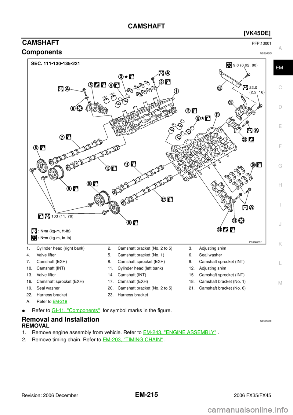
CAMSHAFTPFP:13001
ComponentsNBS003ID
�Refer to GI-11, "Components" for symbol marks in the figure.
Removal and InstallationNBS003IE
REMOVAL
1. Remove engine assembly from vehicle. Refer to EM-243, "ENGINE ASSEMBLY" .
2. Remove timing chain. Refer to EM-203, "
TIMING CHAIN" .
1. Cylinder head (right bank) 2. Camshaft bracket (No. 2 to 5) 3. Adjusting shim
4. Valve lifter 5. Camshaft bracket (No. 1) 6. Seal washer
7. Camshaft (EXH) 8. Camshaft sprocket (EXH) 9. Camshaft sprocket (INT)
10. Camshaft (INT) 11. Cylinder head (left bank) 12. Adjusting shim
13. Valve lifter 14. Camshaft (INT) 15. Camshaft sprocket (INT)
16. Camshaft sprocket (EXH) 17. Camshaft (EXH) 18. Camshaft bracket (No. 1)
19. Seal washer 20. Camshaft bracket (No. 2 to 5) 21. Camshaft bracket (No. 6)
22. Harness bracket 23. Harness bracket
A. Refer to EM-219
.
PBIC4661E
Page 3010 of 4462
![INFINITI FX35 2006 Service Manual EM-216
[VK45DE]
CAMSHAFT
Revision: 2006 December 2006 FX35/FX45
3. With hexagonal part of camshaft locked with wrench, loosen bolts securing camshaft sprocket to remove camshaft sprocket.
CAUTION:
�](/manual-img/42/57019/w960_57019-3009.png "INFINITI FX35 2006 Service Manual EM-216
[VK45DE]
CAMSHAFT
Revision: 2006 December 2006 FX35/FX45
3. With hexagonal part of camshaft locked with wrench, loosen bolts securing camshaft sprocket to remove camshaft sprocket.
CAUTION:
�")
EM-216
[VK45DE]
CAMSHAFT
Revision: 2006 December 2006 FX35/FX45
3. With hexagonal part of camshaft locked with wrench, loosen bolts securing camshaft sprocket to remove camshaft sprocket.
CAUTION:
�Do not loosen mounting bolts with securing anything
other than the camshaft hexagonal portion or with ten-
sioning the timing chain.
�After removing timing chain, do not turn crankshaft and
camshaft separately, or valves will strike the piston head.
4. Remove intake and exhaust camshaft brackets.
�Mark camshafts, camshaft brackets and bolts so placed in the same position and direction for installa-
tion.
�Equally loosen camshaft brackets and bolts in several steps in
reverse order as shown in the figure.
�Lightly tapping with plastic hammer, remove camshaft bracket
(No. 1) and camshaft bracket (No. 6).
NOTE:
The bottom surface of each bracket will be stuck to cylinder
head because of liquid gasket.
5. Remove camshaft.
6. Remove adjusting shim and valve lifter if necessary.
�Identify installation positions, and store them without mixing them up.
INSPECTION AFTER REMOVAL
Camshaft Runout
1. Put V-block on precise flat table, and support No. 2 and 5 journal of camshaft.
CAUTION:
Do not support journal No. 1 (on the side of camshaft
sprocket) because it has a different diameter from the other
four locations.
2. Set dial indicator vertically to No. 3 journal.
3. Turn camshaft to one direction with hands, and measure the camshaft runout on dial indicator. (Total indicator reading)
4. If it exceeds the limit, replace camshaft.
PBIC0030E
PBIC0031E
Limit : 0.02 mm (0.001 in)PBIC2499E
Page 3013 of 4462
![INFINITI FX35 2006 Service Manual CAMSHAFT EM-219
[VK45DE]
C
D E
F
G H
I
J
K L
M A
EM
Revision: 2006 December 2006 FX35/FX45
Valve Lifter Clearance
VALVE LIFTER OUTER DIAMETER
�Measure the outer diameter of valve lifter wi](/manual-img/42/57019/w960_57019-3012.png "INFINITI FX35 2006 Service Manual CAMSHAFT EM-219
[VK45DE]
C
D E
F
G H
I
J
K L
M A
EM
Revision: 2006 December 2006 FX35/FX45
Valve Lifter Clearance
VALVE LIFTER OUTER DIAMETER
�Measure the outer diameter of valve lifter wi")
CAMSHAFT EM-219
[VK45DE]
C
D E
F
G H
I
J
K L
M A
EM
Revision: 2006 December 2006 FX35/FX45
Valve Lifter Clearance
VALVE LIFTER OUTER DIAMETER
�Measure the outer diameter of valve lifter with micrometer.
VALVE LIFTER HOLE DIAMETER
�Measure the inner diameter of valve lifter hole of cylinder head
with inside micrometer.
VALVE LIFTER CLEARANCE
�(Valve lifter clearance) = (Valve lifter hole diameter) – (Valve lifter outer diameter)
�If the calculated value is out of the standard, referring to each standard of valve lifter outer diameter and
valve lifter hole diameter, replace either or both valve lifter and cylinder head.
INSTALLATION
1. Install valve lifters and adjusting shims if removed.
�Install it in the original position.
2. Install camshafts.
�Follow your identification marks made during removal, or fol-
low the identification marks that are present on new cam-
shafts for proper placement and direction. Standard : 33.965 - 33.975 mm (1.3372 - 1.3376 in)
SEM961E
Standard : 34.000 - 34.016 mm (1.3386 - 1.3392 in)
SEM867E
Standard : 0.025 - 0.51 mm (0.0010 - 0.0200 in)
Bank INT/EXH
Identification
rib Paint marks
Identification
mark
M1 M2
RH INT Yes White No RH
EXH Yes No White RH
LH INT No White No LH
EXH No No White LH
PBIC2355E
![INFINITI FX35 2006 Service Manual EM-208
[VK45DE]
TIMING CHAIN
Revision: 2006 December 2006 FX35/FX45
INSPECTION AFTER REMOVAL
Timing Chain
Check for cracks and any excessive wear at link plates and roller
links of timing chain. Rep](/manual-img/42/57019/w960_57019-3001.png "INFINITI FX35 2006 Service Manual EM-208
[VK45DE]
TIMING CHAIN
Revision: 2006 December 2006 FX35/FX45
INSPECTION AFTER REMOVAL
Timing Chain
Check for cracks and any excessive wear at link plates and roller
links of timing chain. Rep")