Page 3835 of 4462

CHASSIS AND BODY MAINTENANCE MA-35
C
D E
F
G H
I
J
K
M A
B
MA
Revision: 2006 December 2006 FX35/FX45
Tire RotationNLS0006U
�After rotation the tires, adjust the tire pressure.
�Retighten the wheel nuts when the vehicle has been driven for
1,000 km (600 miles) (also in cases of a flat tire, etc.).
CAUTION:
�Do not include the T-type spare tire when rotating the tires.
�When installing wheels, tighten them diagonally by dividing
the work two to three times in order to prevent the wheels
from developing any distortion.
Checking Brake Fluid Level and LeaksNLS0006V
�If fluid level is extremely low, check brake system for leaks.
Checking Brake Lines and CablesNLS0006W
�Check brake fluid lines and parking brake cables for improper
attachment, leaks, chafing, abrasions, deterioration, etc.
Changing Brake FluidNLS0006X
1. Drain brake fluid from each bleed valve.
2. Refill until new brake fluid comes out from each bleed valve. Use same procedure as in bleeding hydraulic system to refill
brake fluid.
Refer to BR-10, "
Bleeding Brake System" .
�Refill with recommended Genuine Nissan Super Heavy Duty
Brake Fluid or equivalent DOT 3 (US FMVSS No. 116).
Refer to MA-12, "
RECOMMENDED FLUIDS AND LUBRI-
CANTS" .
�Never reuse drained brake fluid.
�Be careful not to splash brake fluid on painted areas. Tightening torque of wheel nut
: 108 N·m (11 kg, 80 ft-lb)
SMA829C
SBR451D
SBR389C
SBR419C
Page 3847 of 4462
PARKING BRAKE CONTROL PB-5
C
D E
G H
I
J
K L
M A
B
PB
Revision: 2006 December 2006 FX35/FX45
12. Remove right and left rear cables installation nuts, bolts, and remove right and left rear cable assembly from the vehicle.
INSTALLATION
1. Install in the reverse order of removal. Tighten the mounting bolts and nuts to the specified torque. Referto PB-4, "
Components" .
CAUTION:
Do not reuse adjusting nut after removing it.
2. Adjust parking brake. Refer to PB-3, "
ADJUSTMENT" .
Page 3937 of 4462
NOISE, VIBRATION AND HARSHNESS (NVH) TROUBLESHOOTING PR-3
C E F
G H
I
J
K L
M A
B
PR
Revision: 2006 December 2006 FX35/FX45
NOISE, VIBRATION AND HARSHNESS (NVH) TROUBLESHOOTINGPFP:00003
NVH Troubleshooting ChartNDS000AS
Use the chart below to help you find the cause of the symptom. If necessary, repair or replace these parts.
× : Applicable
Reference page
Front
PR-4—
—
—
—
PR-4PR-5
NVH in FFD and RFD section
NVH in FAX, RAX, FSU, and RSU section
NVH in WT section
NVH in WT section
NVH in RAX section
NVH in BR section
NVH in PS section
RearPR-7PR-11—
PR-8—
PR-7PR-10
Possible cause and SUSPECTED PARTS
Uneven rotating torque
Center bearing improper installation
Excessive center bearing axial end play
Center bearing mounting (insulator) cracks, damage or deterioration
Excessive joint angle
Rotation imbalance
Excessive runout
DIFFERENTIAL
AXLE AND SUSPENSION
TIRES
ROAD WHEEL
DRIVE SHAFT
BRAKES
STEERING
Symptom Noise
××××××××××××××
Shake × × ××××××
Vibration ××××××× ×× × ×
Page 3940 of 4462
PR-6
FRONT PROPELLER SHAFT
Revision: 2006 December 2006 FX35/FX45
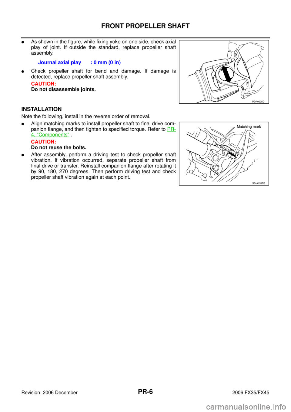
�As shown in the figure, while fixing yoke on one side, check axial
play of joint. If outside the standard, replace propeller shaft
assembly.
�Check propeller shaft for bend and damage. If damage is
detected, replace propeller shaft assembly.
CAUTION:
Do not disassemble joints.
INSTALLATION
Note the following, install in the reverse order of removal.
�Align matching marks to install propeller shaft to final drive com-
panion flange, and then tighten to specified torque. Refer to PR-
4, "Components" .
CAUTION:
Do not reuse the bolts.
�After assembly, perform a driving test to check propeller shaft
vibration. If vibration occurred, separate propeller shaft from
final drive or transfer. Reinstall companion flange after rotating it
by 90, 180, 270 degrees. Then perform driving test and check
propeller shaft vibration again at each point. Journal axial play : 0 mm (0 in)
PDA0005D
SDIA1517E
Page 3945 of 4462

REAR PROPELLER SHAFT PR-11
C E F
G H
I
J
K L
M A
B
PR
Revision: 2006 December 2006 FX35/FX45
INSTALLATION
Note the following, and install in the reverse order of removal.
CAUTION:
Avoid damaging the rebro joint boot, protect it with a shop towel or equivalent.
�Align matching marks to install propeller shaft to final drive and transfer (AWD models only) companion
flanges, and then tighten to specified torque. Refer to PR-8, "
Components" .
�Install center bearing mounting bracket (Upper) with its arrow
mark facing forward.
�Adjust position of mounting bracket sliding back and forth to pre-
vent play in thrust direction of center bearing insulator. Install
bracket to vehicle.
�After assembly, perform a driving test to check propeller shaft
vibration. If vibration occurred, separate propeller shaft from
final drive. Reinstall companion flange after rotating it by 60,
120, 180, 240, 300 degrees. Then perform driving test and
check propeller shaft vibration again at each point.
�If propeller shaft or final drive has been replaced, connect them
as follows:
1. Install the propeller shaft while aligning its matching mark A with the matching mark B on the joint as close as possible.
2. Tighten the joint bolts to the specified torque. Refer to PR-8,
"Components" .
CAUTION:
Do not reuse the bolts, nuts and washers.
PDIA0017E
SDIA2049E
Page 3947 of 4462
 and 3F80A-1VL107
(VK45DE/AWD) type
�Install the")
REAR PROPELLER SHAFT PR-13
C E F
G H
I
J
K L
M A
B
PR
Revision: 2006 December 2006 FX35/FX45
ASSEMBLY
1. For the 3S80A-1VL107 (VQ35DE/2WD) and 3F80A-1VL107
(VK45DE/AWD) type
�Install the center bearing with its “F” mark facing the front of
the vehicle.
For the 3F80A-1VL107 (VQ35DE/AWD) type
�Install the center bearing with its “F” mark facing the rear of
the vehicle.
2. Apply multi-purpose grease to the each face of the washer, then install washer.
3. Install the center flange onto the propeller shaft with aligning the marks that are marked while removal.
4. Install and tighten the lock nut to specified torque. Refer to PR-8, "
Components" .
CAUTION:
Do not use the lock nut.
5. Place a piece of wood under the center flange, stake the lock nut against the propeller shaft groove. [For the 3S80A-1VL107
(VQ35DE/2WD) and 3F80A-1VL107 (VQ35DE/AWD) type]
6. Assemble the 1st and 2nd shaft propeller shafts while aligning the matching marks that are marked during removal.
7. Install and tighten the bolts/nuts and tighten them to specified torque. Refer to PR-8, "
Components" .
CAUTION:
Do not reuse the bolts, nuts and washers.
SDIA1542E
SDIA1543E
SDIA1538E
Page 3953 of 4462
NGS000BQ
The actual shapes of Kent-Moore tools may differ")
PREPARATION PS-5
C
D E
F
H I
J
K L
M A
B
PS
Revision: 2006 December 2006 FX35/FX45
PREPARATIONPFP:00002
Special Service Tools (SST)NGS000BQ
The actual shapes of Kent-Moore tools may differ from those of special service tools illustrated here.
Tool number
(Kent-Moore No.)
Tool name Description
ST3127 S000
(See J25765-A)
Preload gauge
1. GG9103000
(J25765-A)
Torque wrench
2. HT62940000
( — )
Socket adapter
3. HT62900000
( — )
Socket adapter Inspecting of sliding torque, steering
torque, and rotating torque for ball joint
HT72520000
(J25730-A)
Ball joint remover
a: 33 mm (1.3 in)
b: 50 mm (1.97 in)
r: 11.5 mm (0.45 in) Removing steering outer socket
KV4810 5400
(J-46213)
Rear cover wrench
a: 21.6 mm (0.85 in)
b: 34.9 mm (1.37 in) Removing rear cover
KV48104400
( — )
Teflon ring correcting tool
a: 50 mm (1.97 in) dia.
b: 36 mm (1.42 in) dia.
c: 100 mm (3.94 in) Installing of rack Teflon ring
KV48103400
( — )
Torque adapter Inspecting rotating torque
S-NT541
NT546
SGIA0516E
S-NT550
ZZA0824D
Page 3955 of 4462
 TROUBLESHOOTING PS-7
C
D E
F
H I
J
K L
M A
B
PS
Revision: 2006 December 2006 FX35/FX45
NOISE, VIBRATION AND HARSHNESS (NVH) TROUBLESHOOTINGPFP:00003
NV")
NOISE, VIBRATION AND HARSHNESS (NVH) TROUBLESHOOTING PS-7
C
D E
F
H I
J
K L
M A
B
PS
Revision: 2006 December 2006 FX35/FX45
NOISE, VIBRATION AND HARSHNESS (NVH) TROUBLESHOOTINGPFP:00003
NVH Troubleshooting ChartNGS000BS
Use chart below to help you find the cause of the symptom. If necessary, repair or replace these parts.
× : Applicable Reference page
PS-8PS-8PS-23PS-23PS-23PS-8PS-10PS-10
EM-15
,
EM-174PS-10PS-12PS-17PS-12PS-12PS-17
NVH in PR section
NVH in RFD section
NVH in FAX, RAX, FSU, RSU section NVH in WT section
NVH in WT section
NVH in FAX section
NVH in BR section
Possible cause and suspected parts
Fluid level
Air in hydraulic system
Outer socket ball joint swinging force
Outer socket ball joint rotating torque
Outer socket ball joint end play
Steering fluid leakage
Steering wheel play
Steering gear rack sliding force
Drive belt looseness
Improper steering wheel
Improper installation or looseness of tilt lock lever
Mounting rubber deterioration
Steering column deformation or damage
Improper installation or looseness of steering column
Steering linkage looseness
PROPELLER SHAFT
DIFFERENTIAL
AXLE and SUSPENSION
TIRES
ROAD WHEEL
DRIVE SHAFT
BRAKES
Symptom STEERING Noise
× × ××××× × × ×××××× ×
Shake ××× × ×××× ×
Vibration ××××× × ×× ×
Shimmy ××× × ××× ×
Judder ××××××

 TROUBLESHOOTING PR-3
C E F
G H
I
J
K L
M A
B
PR
Revision: 2006 December 2006 FX35/FX45
NOISE, VIBRATION AND HARSHNESS (NVH) TROUBLESHOOTINGPFP:00003
NVH")