Page 4371 of 4462

ROAD WHEEL TIRE ASSEMBLY WT-9
C
D
F
G H
I
J
K L
M A
B
WT
Revision: 2006 December 2006 FX35/FX45
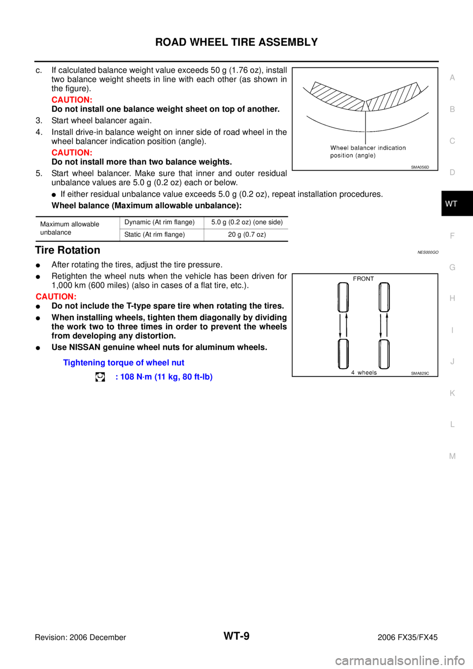
c. If calculated balance weight value exceeds 50 g (1.76 oz), install two balance weight sheets in line with each other (as shown in
the figure).
CAUTION:
Do not install one balance weight sheet on top of another.
3. Start wheel balancer again.
4. Install drive-in balance weight on inner side of road wheel in the wheel balancer indication position (angle).
CAUTION:
Do not install more than two balance weights.
5. Start wheel balancer. Make sure that inner and outer residual unbalance values are 5.0 g (0.2 oz) each or below.
�If either residual unbalance value exceeds 5.0 g (0.2 oz), repeat installation procedures.
Wheel balance (Maximum allowable unbalance):
Tire RotationNES000GO
�After rotating the tires, adjust the tire pressure.
�Retighten the wheel nuts when the vehicle has been driven for
1,000 km (600 miles) (also in cases of a flat tire, etc.).
CAUTION:
�Do not include the T-type spare tire when rotating the tires.
�When installing wheels, tighten them diagonally by dividing
the work two to three times in order to prevent the wheels
from developing any distortion.
�Use NISSAN genuine wheel nuts for aluminum wheels.
Maximum allowable
unbalance Dynamic (At rim flange) 5.0 g (0.2 oz) (one side)
Static (At rim flange) 20 g (0.7 oz)
SMA056D
Tightening torque of wheel nut : 108 N·m (11 kg, 80 ft-lb)
SMA829C
Page 4435 of 4462

FRONT WIPER AND WASHER SYSTEM WW-33
C
D E
F
G H
I
J
L
M A
B
WW
Revision: 2006 December 2006 FX35/FX45
Removal and Installation of Front Wiper Arms, Adjustment of Wiper Arms Stop
Location
NKS0032S
REMOVAL
1. Operate wiper motor, and stop it at the auto stop position.
2. Remove washer tube from washer tube joint.
3. Remove wiper arm mounting nuts and wiper arm from vehicle.
INSTALLATION
1. Clean up the pivot area as illustrated. This will reduce possibility of wiper arm looseness.
2. Prior to wiper arm installation, turn on wiper switch to operate wiper motor and then turn it “OFF” (auto stop).
3. Push wiper arm onto pivot shaft, paying attention to blind spline.
4. Attach washer tube to washer tube joint.
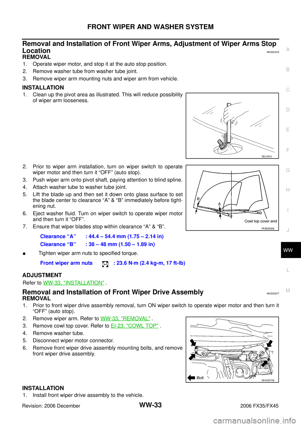
5. Lift the blade up and then set it down onto glass surface to set the blade center to clearance “A” & “B” immediately before tight-
ening nut.
6. Eject washer fluid. Turn on wiper switch to operate wiper motor and then turn it “OFF”.
7. Ensure that wiper blades stop within clearance “A” & “B”.
�Tighten wiper arm nuts to specified torque.
ADJUSTMENT
Refer to WW-33, "INSTALLATION" .
Removal and Installation of Front Wiper Drive Assembly NKS0032T
REMOVAL
1. Prior to front wiper drive assembly removal, turn ON wiper switch to operate wiper motor and then turn it
“OFF” (auto stop).
2. Remove wiper arm. Refer to WW-33, "
REMOVAL" .
3. Remove cowl top cover. Refer to EI-23, "
COWL TOP" .
4. Remove washer tube.
5. Disconnect wiper motor connector.
6. Remove front wiper drive assembly mounting bolts, and remove front wiper drive assembly.
INSTALLATION
1. Install front wiper drive assembly to the vehicle.
SEL024J
Clearance “A” : 44.4 – 54.4 mm (1.75 – 2.14 in)
Clearance “B” : 38 – 48 mm (1.50 – 1.89 in)
Front wiper arm nuts : 23.6 N·m (2.4 kg-m, 17 ft-lb)
PKIB3556E
SKIA5070E
Page 4453 of 4462

REAR WIPER AND WASHER SYSTEM WW-51
C
D E
F
G H
I
J
L
M A
B
WW
Revision: 2006 December 2006 FX35/FX45
Removal and Installation of Rear Wiper Arm, Adjustment of Wiper Arms Stop
Location
NKS0033G
REMOVAL
1. Operate wiper motor, and stop it at the auto stop position.
2. Remove cover wiper arm.
3. Remove wiper arm nut, and remove wiper arm from vehicle.
INSTALLATION
1. Prior to wiper arm installation, turn on wiper switch to operate wiper motor and then turn it “OFF” (auto stop).
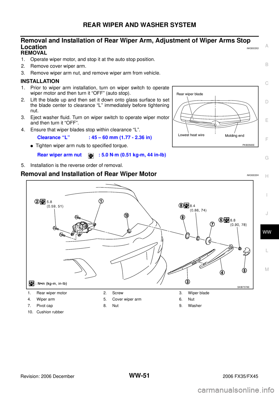
2. Lift the blade up and then set it down onto glass surface to set the blade center to clearance “L” immediately before tightening
nut.
3. Eject washer fluid. Turn on wiper switch to operate wiper motor and then turn it “OFF”.
4. Ensure that wiper blades stop within clearance “L”.
�Tighten wiper arm nuts to specified torque.
5. Installation is the reverse order of removal.
Removal and Installation of Rear Wiper Motor NKS0033H
Clearance “L” : 45 – 60 mm (1.77 - 2.36 in)
Rear wiper arm nut : 5.0 N·m (0.51 kg-m, 44 in-lb)
PKIB3565E
1. Rear wiper motor 2. Screw 3. Wiper blade
4. Wiper arm 5. Cover wiper arm 6. Nut
7. Pivot cap 8. Nut 9. Washer
10. Cushion rubber
SKIB7578E
Page 4461 of 4462
HORN
WW-59
C
D E
F
G H
I
J
L
M A
B
WW
Revision: 2006 December 2006 FX35/FX45
Removal and InstallationNKS0033X
REMOVAL
1. Remove front grille. Refer to EI-22, "FRONT GRILLE" .
2. Disconnect all horn connectors.
3. Remove horn mounting bolt and remove horn from vehicle.
INSTALLATION
Installation is the reverse order of removal.
�Tighten horn bolt to specified torque.
SKIA5093E
Horn mounting bolt : 5.8 N·m (0.59 kg-m, 51 in-lb)