Page 3958 of 4462
PS-10
STEERING WHEEL
Revision: 2006 December 2006 FX35/FX45
STEERING WHEELPFP:48430
On-Vehicle Inspection and ServiceNGS000BW
CHECKING CONDITION OF INSTALLATION
�Check installation condition of steering gear assembly, front suspension, axle and steering column.
�Check if movement exists when steering wheel is moved up and down, to the left and right and to the axial
direction.
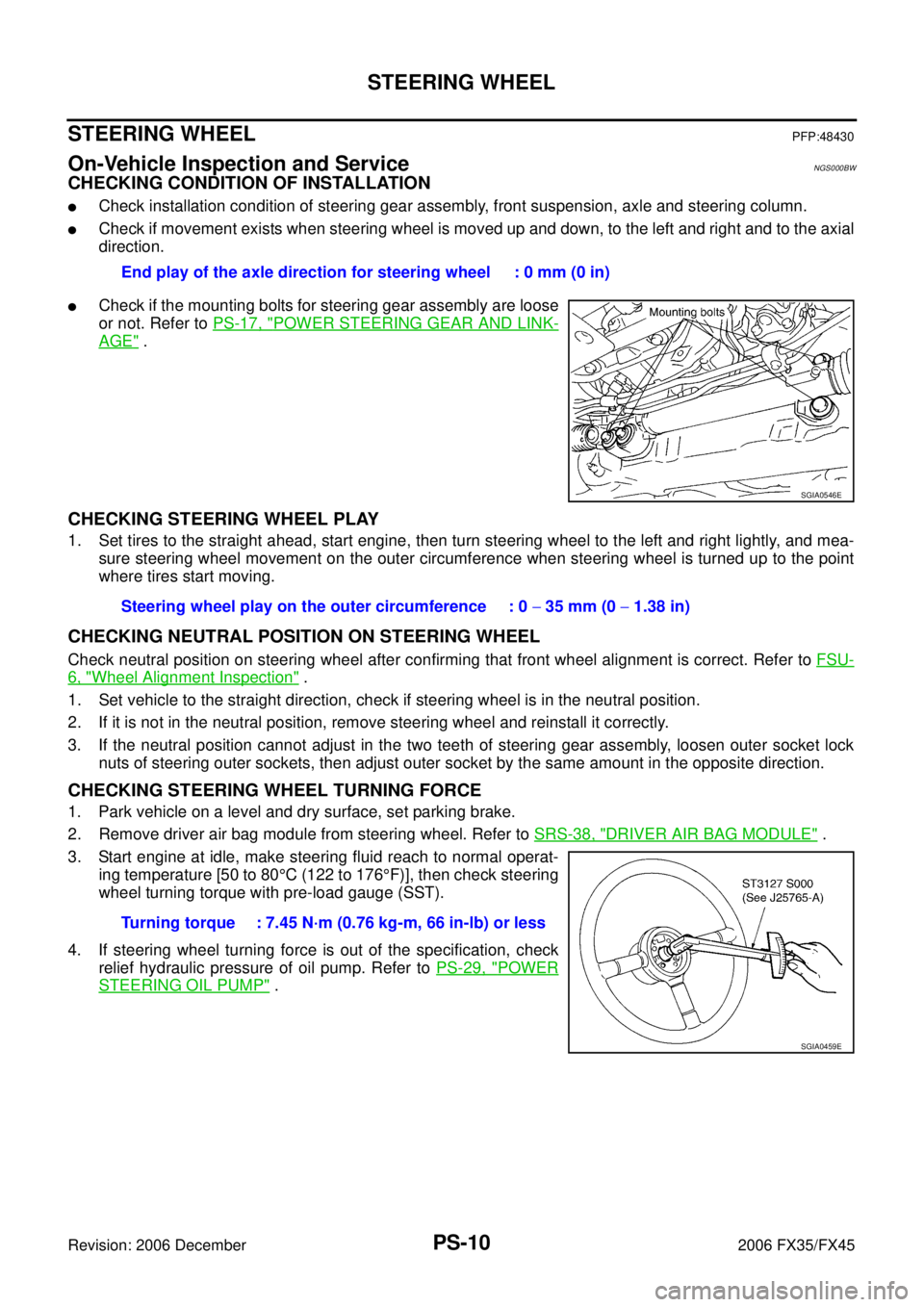
�Check if the mounting bolts for steering gear assembly are loose
or not. Refer to PS-17, "
POWER STEERING GEAR AND LINK-
AGE" .
CHECKING STEERING WHEEL PLAY
1. Set tires to the straight ahead, start engine, then turn steering wheel to the left and right lightly, and mea-
sure steering wheel movement on the outer circumference when steering wheel is turned up to the point
where tires start moving.
CHECKING NEUTRAL POSITION ON STEERING WHEEL
Check neutral position on steering wheel after confirming that front wheel alignment is correct. Refer to FSU-
6, "Wheel Alignment Inspection" .
1. Set vehicle to the straight direction, check if steering wheel is in the neutral position.
2. If it is not in the neutral position, remove steering wheel and reinstall it correctly.
3. If the neutral position cannot adjust in the two teeth of steering gear assembly, loosen outer socket lock nuts of steering outer sockets, then adjust outer socket by the same amount in the opposite direction.
CHECKING STEERING WHEEL TURNING FORCE
1. Park vehicle on a level and dry surface, set parking brake.
2. Remove driver air bag module from steering wheel. Refer to SRS-38, "
DRIVER AIR BAG MODULE" .
3. Start engine at idle, make steering fluid reach to normal operat- ing temperature [50 to 80 °C (122 to 176 °F)], then check steering
wheel turning torque with pre-load gauge (SST).
4. If steering wheel turning force is out of the specification, check relief hydraulic pressure of oil pump. Refer to PS-29, "
POWER
STEERING OIL PUMP" .
End play of the axle direction for steering wheel : 0 mm (0 in)
SGIA0546E
Steering wheel play on the outer circumference : 0
− 35 mm (0 − 1.38 in)
Turning torque : 7.45 N·m (0.76 kg-m, 66 in-lb) or less
SGIA0459E
Page 3962 of 4462
PS-14
STEERING COLUMN
Revision: 2006 December 2006 FX35/FX45
INSPECTION AFTER REMOVAL
�Check if there is something wrong with jacket tube of steering column assembly and collar etc. And then if
they are damaged, replace with new one.
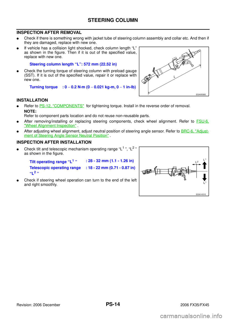
�If vehicle has a collision light shocked, check column length “L”
as shown in the figure. Then if it is out of the specified value,
replace with new one.
�Check the turning torque of steering column with preload gauge
(SST). If it is out of the specified value, repair it or replace with
new one.
INSTALLATION
�Refer to PS-12, "COMPONENTS" for tightening torque. Install in the reverse order of removal.
NOTE:
Refer to component parts location and do not reuse non-reusable parts.
�After removing/installing or replacing steering components, check wheel alignment. Refer to FSU-6,
"Wheel Alignment Inspection" .
�After adjusting wheel alignment, adjust neutral position of steering angle sensor. Refer to BRC-6, "Adjust-
ment of Steering Angle Sensor Neutral Position" .
INSPECTION AFTER INSTALLATION
�Check tilt and telescopic mechanism operating range “L1 ”, “L2 ”
as shown in the figure.
�Check if steering wheel operation can turn to the end of the left
and right smoothly. Steering column length “L”: 572 mm (22.52 in)
Turning torque : 0 − 0.2 N·m (0 − 0.021 kg-m, 0 − 1 in-lb)
SGIA0556E
Tilt operating range “L1 ” : 28 - 32 mm (1.1 - 1.26 in)
Telescopic operating range
“L
2 ” : 18 - 22 mm (0.71 - 0.87 in)
SGIA1431E
Page 3964 of 4462
PS-16
STEERING COLUMN
Revision: 2006 December 2006 FX35/FX45
DISASSEMBLY
Disassemble the parts from jacket tube. The parts to be disassembled are shown in the figure.
ASSEMBLY
Refer to PS-15, "COMPONENTS" for tightening torque. Install in the reverse order of disassembly.
1. Meter bracket 2. Jacket tube assembly 3. Upper joint
4. Spring 5. Lock nut 6. Lock block
7. Telescopic lock guide 8. Bush spacer 9. Tilt link assembly
10. Cooler 11. Tilt unit assembly 12. Tilt sensor assembly
13. Connector assembly 14. Clamp 15. Spring
16. Telescopic unit assembly 17. Telescopic sensor assembly
Page 3966 of 4462
PS-18
POWER STEERING GEAR AND LINKAGE
Revision: 2006 December 2006 FX35/FX45
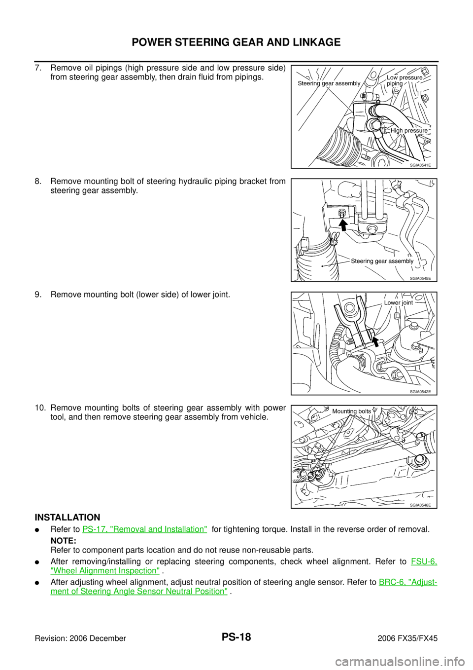
7. Remove oil pipings (high pressure side and low pressure side) from steering gear assembly, then drain fluid from pipings.
8. Remove mounting bolt of steering hydraulic piping bracket from steering gear assembly.
9. Remove mounting bolt (lower side) of lower joint.
10. Remove mounting bolts of steering gear assembly with power tool, and then remove steering gear assembly from vehicle.
INSTALLATION
�Refer to PS-17, "Removal and Installation" for tightening torque. Install in the reverse order of removal.
NOTE:
Refer to component parts location and do not reuse non-reusable parts.
�After removing/installing or replacing steering components, check wheel alignment. Refer to FSU-6,
"Wheel Alignment Inspection" .
�After adjusting wheel alignment, adjust neutral position of steering angle sensor. Refer to BRC-6, "Adjust-
ment of Steering Angle Sensor Neutral Position" .
SGIA0541E
SGIA0545E
SGIA0542E
SGIA0546E
Page 3971 of 4462
POWER STEERING GEAR AND LINKAGE PS-23
C
D E
F
H I
J
K L
M A
B
PS
Revision: 2006 December 2006 FX35/FX45
INSPECTION AFTER DISASSEMBLY
Boot
Check boot for cracks and deformation. Replace it, if necessary.
Rack
Check rack for damage and wear. Replace it, if necessary.
Sub-Gear Assembly
�Check pinion gear for damage and wear. Replace it, if necessary.
�Check bearing while rotating it. Replace bearing if bearing ball race was dented, worn, or damaged.
Gear Housing Assembly
Check gear housing assembly for damage and scratches (inner wall). Replace it, if necessary.
Outer Socket and Inner Socket
Swing Torque
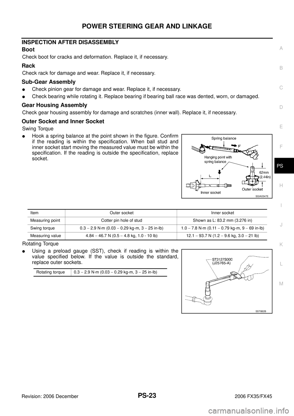
�Hook a spring balance at the point shown in the figure. Confirm
if the reading is within the specification. When ball stud and
inner socket start moving the measured value must be within the
specification. If the reading is outside the specification, replace
socket.
Rotating Torque
�Using a preload gauge (SST), check if reading is within the
value specified below. If the value is outside the standard,
replace outer sockets.
SGIA0547E
Item Outer socket Inner socket
Measuring point Cotter pin hole of stud Shown as L: 83.2 mm (3.276 in)
Swing torque 0.3 − 2.9 N·m (0.03 − 0.29 kg-m, 3 − 25 in-lb) 1.0 − 7.8 N·m (0.11 − 0.79 kg-m, 9 − 69 in-lb)
Measuring value 4.84 − 46.7 N (0.5 − 4.8 kg, 1.0 - 10 lb) 12.1 − 93.7 N (1.2 − 9.6 kg, 3.0 − 21 lb)
Rotating torque 0.3 − 2.9 N·m (0.03 − 0.29 kg-m, 3 − 25 in-lb)
SST882B
Page 3973 of 4462
POWER STEERING GEAR AND LINKAGE PS-25
C
D E
F
H I
J
K L
M A
B
PS
Revision: 2006 December 2006 FX35/FX45
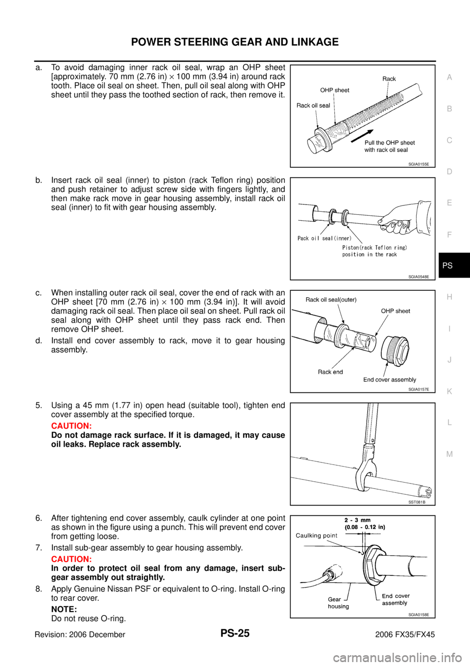
a. To avoid damaging inner rack oil seal, wrap an OHP sheet [approximately. 70 mm (2.76 in) × 100 mm (3.94 in) around rack
tooth. Place oil seal on sheet. Then, pull oil seal along with OHP
sheet until they pass the toothed section of rack, then remove it.
b. Insert rack oil seal (inner) to piston (rack Teflon ring) position and push retainer to adjust screw side with fingers lightly, and
then make rack move in gear housing assembly, install rack oil
seal (inner) to fit with gear housing assembly.
c. When installing outer rack oil seal, cover the end of rack with an OHP sheet [70 mm (2.76 in) × 100 mm (3.94 in)]. It will avoid
damaging rack oil seal. Then place oil seal on sheet. Pull rack oil
seal along with OHP sheet until they pass rack end. Then
remove OHP sheet.
d. Install end cover assembly to rack, move it to gear housing assembly.
5. Using a 45 mm (1.77 in) open head (suitable tool), tighten end cover assembly at the specified torque.
CAUTION:
Do not damage rack surface. If it is damaged, it may cause
oil leaks. Replace rack assembly.
6. After tightening end cover assembly, caulk cylinder at one point as shown in the figure using a punch. This will prevent end cover
from getting loose.
7. Install sub-gear assembly to gear housing assembly. CAUTION:
In order to protect oil seal from any damage, insert sub-
gear assembly out straightly.
8. Apply Genuine Nissan PSF or equivalent to O-ring. Install O-ring to rear cover.
NOTE:
Do not reuse O-ring.
SGIA0155E
SGIA0548E
SGIA0157E
SST081B
SGIA0158E
Page 3974 of 4462
PS-26
POWER STEERING GEAR AND LINKAGE
Revision: 2006 December 2006 FX35/FX45
9. Use a rear cover wrench (SST), install rear cover to gear housing assembly.
10. Confirm projection on rear cover cap nearly fit with marking position on gear housing assembly.
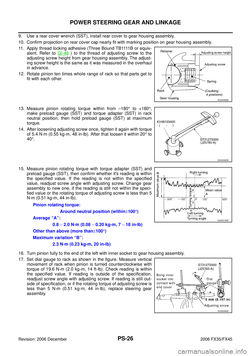
11 . A p p l y t h r e a d l o c k i n g a d h e s i v e ( T h r e e B o u n d T B 1111 B o r e q u i v - alent. Refer to GI-48
) to the thread of adjusting screw to the
adjusting screw height from gear housing assembly. The adjust-
ing screw height is the same as it was measured in the overhaul
in advance.
12. Rotate pinion ten times whole range of rack so that parts get to fit with each other.
13. Measure pinion rotating torque within from –180 ° to +180 °,
make preload gauge (SST) and torque adapter (SST) in rack
neutral position, then hold preload gauge (SST) at maximum
torque.
14. After loosening adjusting screw once, tighten it again with torque of 5.4 N·m (0.55 kg-m, 48 in-lb). After that loosen it within 20 ° to
40 °.
15. Measure pinion rotating torque with torque adapter (SST) and preload gauge (SST), then confirm whether it's reading is within
the specified value. If the reading is not within the specified
value, readjust screw angle with adjusting screw. Change gear
assembly to new one, if the reading is still not within the speci-
fied value or the rotating torque of adjusting screw is less than 5
N·m (0.51 kg-m, 44 in-lb).
16. Turn pinion fully to the end of the left with inner socket to gear housing assembly.
17. Set dial gauge to rack as shown in the figure. Measure vertical movement of rack when pinion is turned counterclockwise with
torque of 19.6 N·m (2.0 kg-m, 14 ft-lb). Check reading is within
the specified value. If reading is outside of the specification,
readjust screw angle with adjusting screw. If reading is still out-
side of specification, or if the rotating torque of adjusting screw is
less than 5 N·m (0.51 kg-m, 44 in-lb), replace steering gear
assembly.
SGIA0568E
SGIA0483E
Pinion rotating torque:
Around neutral position (within ±100 °)
Average “A”:
0.8 − 2.0 N·m (0.08 − 0.20 kg-m, 7 − 18 in-lb)
Other than above (more than ±100 °)
Maximum variation “B”:
2.3 N·m (0.23 kg-m, 20 in-lb)
SGIA0160E
SGIA0484E
Page 3976 of 4462
PS-28
POWER STEERING GEAR AND LINKAGE
Revision: 2006 December 2006 FX35/FX45
24. Tighten lightly inner socket in specified length “L”, then tighten lock nut at specified torque. Refer to PS-20, "
Disassembly and
Assembly" . Reconfirm if inner socket length is within limit of
specified length “L”.
CAUTION:
Perform toe-in adjustment after this procedure. Length
achieved after toe-in adjustment is not necessary value
given here. Inner socket length “L” : 135.2 mm (5.32 in)
SGIA0167E