Page 3122 of 4462
 and drain ge")
FFD-8
DIFFERENTIAL GEAR OIL
Revision: 2006 December 2006 FX35/FX45
DIFFERENTIAL GEAR OILPFP:KLD30
Changing Differential Gear OilNDS000CP
DRAINING
1. Stop engine.
2. Remove drain plug (1) and drain gear oil.
3. Set a gasket on drain plug (1) and install it to final drive assem- bly and tighten to the specified torque. Refer to FFD-17, "
COM-
PONENTS (VQ35DE MODELS)" , FFD-19, "COMPONENTS
(VK45DE MODELS)" .
CAUTION:
Do not reuse gasket.
FILLING
1. Remove filler plug (1). Fill with new gear oil until oil level reaches
the specified level near filler plug mounting hole.
2. After refilling oil, check oil level. Set a gasket to filler plug (1), then install it to final drive assembly. Refer to FFD-17, "
COMPO-
NENTS (VQ35DE MODELS)" , FFD-19, "COMPONENTS
(VK45DE MODELS)" .
CAUTION:
Do not reuse gasket.
Checking Differential Gear OilNDS000CQ
OIL LEAKAGE AND OIL LEVEL
�Make sure that oil is not leaking from final drive assembly or around it.
�Remove filler plug (1) and check oil level from filler plug mount-
ing hole as shown in the figure.
CAUTION:
Do not start engine while checking oil level.
�Set a gasket on filler plug (1) and install it on final drive assem-
bly. Refer to FFD-17, "
COMPONENTS (VQ35DE MODELS)" ,
FFD-19, "
COMPONENTS (VK45DE MODELS)" .
CAUTION:
Do not reuse gasket.
PDIA0781J
Oil grade and Viscosity:
Refer to MA-12, "
Fluids and Lubricants" .
Oil capacity:
Approx. 0.65 (1-3/8 US pt, 1-1/8 Imp pt)
PDIA0782J
PDIA0782J
Page 3124 of 4462

FFD-10
FRONT OIL SEAL
Revision: 2006 December 2006 FX35/FX45
INSTALLATION
1. Apply multi-purpose grease to front oil seal lips.
2. Using the drifts, install front oil seal as shown in figure.
CAUTION:
�Do not reuse oil seal.
�When installing, do not incline oil seal.
3. Align the matching mark (B) of drive pinion with the matching mark (A) of companion flange, and then install the companion
flange (1).
4. Apply anti-corrosion oil to the thread and seat of new drive pin- ion lock nut, and temporarily tighten drive pinion lock nut to drive
pinion.
CAUTION:
Do not reuse drive pinion lock nut.
5. Tighten to drive pinion lock nut, while adjust total preload torque.
CAUTION:
�Adjust to the lower limit of the drive pinion lock nut tight-
ening torque first.
�After adjustment, rotate drive pinion back and forth 2 to 3
times to check for unusual noise, rotation malfunction,
and other malfunctions.
�If measured value is out of the specification, remove final
drive assembly and disassemble drive pinion parts to check
and adjust each part. Refer to FFD-13, "
Removal and Installa-
tion (VQ35DE Models)" ,FFD-15, "Removal and Installation (VK45DE Models)" and FFD-17, "Disas-
sembly and Assembly" .
6. Install front propeller shaft. Refer to PR-5, "
Removal and Installation" .
7. Install side shaft assembly.
8. Install front drive shaft both. Refer to FAX-12, "
Removal and Installation (Left Side)" , FAX-13, "Removal
and Installation (Right Side)" .
9. Refill gear oil to the final drive and check oil level. Refer to FFD-8, "
FILLING" .
10. Check the final drive for oil leakage. Refer to FFD-8, "
OIL LEAKAGE AND OIL LEVEL" .
Tool number A: ST33400001 (J-26082)
B: KV38102510 ( — )
PDIA0786J
PDIA0783J
Tool number A: ST3127S000 (J-25765-A)
Drive pinion lock nut tightening torque: 127.4 - 245.0 N·m (13.0 - 25.0 kg-m, 94 - 181 ft-lb)
Total preload torque: 1.56 - 2.65 N·m (0.16 - 0.27 kg-m, 14 - 23 in-lb)
PDIA0969E
Page 3126 of 4462
FFD-12
SIDE OIL SEAL
Revision: 2006 December 2006 FX35/FX45
5. When oil leaks while removing, check oil level after the installation. Refer to FFD-8, "Checking Differential
Gear Oil" .
Page 3128 of 4462
,")
FFD-14
FRONT FINAL DRIVE ASSEMBLY
Revision: 2006 December 2006 FX35/FX45
�Tighten mounting bolts in the order as described below when
installing front final drive assembly: side of gear carrier (1),
upper side of gear carrier (2), part of carrier cover (3), lower part
of gear carrier (4).
CAUTION:
Align the mating faces of gear carrier and oil pan for instal-
lation.
�When installing breather hoses (1) and tube (2), refer to the fig-
ure.
CAUTION:
Make sure there are no pinched or restricted areas on the
breather hose caused by bending or winding when install-
ing it.
–Make sure the paint mark facing up ( ).
–Securely install the hose until it seats the rounded portion of the
tube ( ).
–Install breather connector as shown in the figure.
–Seat the breather tube bracket end (A) to the machined face (B)
of gear carrier boss.
�When oil leaks while removing final drive assembly, check oil
level after the installation. Refer to FFD-8, "
Changing Differential
Gear Oil" .
PDIA0839J
PDIA0790J
Angle “A”: 0 - 30°
PDIA0841J
PDIA0842E
Page 3130 of 4462
FFD-16
FRONT FINAL DRIVE ASSEMBLY
Revision: 2006 December 2006 FX35/FX45
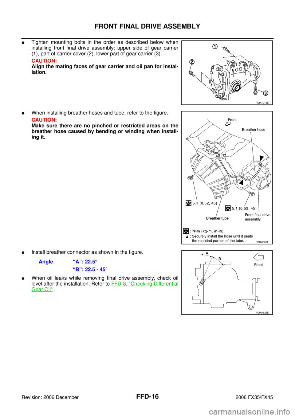
�Tighten mounting bolts in the order as described below when
installing front final drive assembly: upper side of gear carrier
(1), part of carrier cover (2), lower part of gear carrier (3).
CAUTION:
Align the mating faces of gear carrier and oil pan for instal-
lation.
�When installing breather hoses and tube, refer to the figure.
CAUTION:
Make sure there are no pinched or restricted areas on the
breather hose caused by bending or winding when install-
ing it.
�Install breather connector as shown in the figure.
�When oil leaks while removing final drive assembly, check oil
level after the installation. Refer to FFD-8, "
Checking Differential
Gear Oil" .
PDIA1213E
PDIA0661E
Angle “A”: 22.5°
“B”: 22.5 - 45 °
PDIA0822E
Page 3134 of 4462

FFD-20
FRONT FINAL DRIVE ASSEMBLY
Revision: 2006 December 2006 FX35/FX45
ASSEMBLY INSPECTION AND ADJUSTMENT
�Before inspection and adjustment, drain gear oil.
Total Preload Torque
1. Rotate drive pinion back and forth 2 to 3 times to check for unusual noise and rotation malfunction.
2. Rotate drive pinion at least 20 times to check for smooth opera- tion of the bearing.
3. Measure total preload with preload gauge.
NOTE:
Total preload torque = Pinion bearing preload torque + Side
bearing preload torque
�If measured value is out of the specification, disassemble it to
check and adjust each part. Adjust the pinion bearing preload and side bearing preload.
Adjust the pinion bearing preload first, then adjust the side bearing preload.
37. Dust sealed 38. Side shaft
A: Oil seal lip
B: Screw hole
Refer to GI-11, "
Components" and the followings for the symbols in the figure.
: Apply multi-purpose grease.
: Apply gear oil.
: Apply anti-corrosion oil.
: Apply Genuine Silicone RTV or equivalent. Refer to
GI-48, "
Recommended Chemical Products and Sealants" .
: Apply Genuine Medium Strength Thread Locking Sealant or equivalent. Refer to
GI-48, "
Recommended Chemical
Products and Sealants" .
Tool number A: ST3127S000 (J-25765-A)
Total preload torque:
1.56 - 2.65 N·m (0.16 - 0.27 kg-m, 14 - 23 in-lb)
PDIA0792J
When the preload torque is largeOn pinion bearings: Decrease the drive pinion bearing adjusting washer and drive pinion adjusting washer thickness. Refer to FFD-40, "
Drive Pinion Bearing
Adjusting Washer" and FFD-40, "Drive Pinion Adjusting Washer" .
On side bearings: Increase the side bearing adjusting shim thickness. Refer to FFD-40,
"Side Bearing Adjusting Shim" .
When the preload torque is small On pinion bearings: Increase the drive pinion bearing adjusting washer and drive pinion adjusting washer thickness. Refer to FFD-40, "
Drive Pinion Bearing
Adjusting Washer" and FFD-40, "Drive Pinion Adjusting Washer" .
On side bearings: Decrease the side bearing adjusting shim thickness. Refer to FFD-40,
"Side Bearing Adjusting Shim" .
Page 3138 of 4462

FFD-24
FRONT FINAL DRIVE ASSEMBLY
Revision: 2006 December 2006 FX35/FX45
c. If the runout value is still outside of the limit after the check and repair, replace companion flange.
DISASSEMBLY
Side Shaft Assembly
1. Hold extension tube retainer with puller, then press out side shaft using a press.
2. Remove side shaft oil seal (1) from extension tube retainer with a flat- blade screwdriver.
CAUTION:
Be careful not to damage extension tube retainer.
3. Remove side shaft bearing from extension tube retainer.
4. Remove O-ring from extension tube retainer.
5. Remove dust sealed from side shaft.
Differential Assembly
1. Drain gear oil.
2. Remove carrier cover mounting bolts.
3. Remove carrier cover to insert the seal cutter between gear car- rier and carrier cover.
CAUTION:
�Be careful not to damage the mating surface.
�Do not insert flat-bladed screwdriver, this way damage
the mating surface.
4. Remove side retainer.
5. Remove side bearing adjusting shim.
6. Remove O-ring from side retainer.
PDIA0793J
PDIA0794J
Tool number A: KV10111100 (J-37228)
PDIA0795J
PDIA0670E
Page 3148 of 4462
. NOTE:
When reusing drive pinion, align the matching mark (B) of drive
pinion with the matchi")
FFD-34
FRONT FINAL DRIVE ASSEMBLY
Revision: 2006 December 2006 FX35/FX45
10. Install companion flange (1). NOTE:
When reusing drive pinion, align the matching mark (B) of drive
pinion with the matching mark (A) of companion flange, and then
install companion flange (1).
11. Apply anti-corrosion oil to the thread and seat of new drive pin- ion lock nut, and temporarily tighten drive pinion lock nut to drive
pinion.
CAUTION:
Do not reuse drive pinion lock nut.
12. Tighten to drive pinion lock nut, while adjust pinion bearing pre- load torque.
CAUTION:
�Adjust to the lower limit of the drive pinion lock nut tight-
ening torque first.
�After adjustment, rotate drive pinion back and forth 2 to 3
times to check for unusual noise, rotation malfunction,
and other malfunctions.
13. Install differential case assembly. Refer to FFD-34, "
Differential
Assembly" .
CAUTION:
Do not install carrier cover yet.
14. Check and adjust drive gear runout, tooth contact, drive gear to drive pinion backlash, and companion flange runout. Refer to FFD-21, "
Drive Gear Runout" , FFD-21, "Tooth Contact" , FFD-23, "Backlash" ,
FFD-23, "
Companion Flange Runout" .
Recheck above items. Readjust the above description, if necessary.
15. Check total preload torque. Refer to FFD-20, "
Total Preload Torque" .
16. Install carrier cover. Refer to FFD-24, "
Differential Assembly" .
Differential Assembly
1. Install side gear thrust washers with the same thickness as the
ones installed prior to disassembly or reinstall the old ones on
the side gears.
PDIA0799J
Tool number A: ST3127S000 (J-25765-A)
Drive pinion lock nut tightening torque:
127.4 - 245.0 N·m (13.0 - 25.0 kg-m, 94 - 181 ft-lb)
Pinion bearing preload: 0.78 - 1.57 N·m (0.08 - 0.16 kg-m, 7 - 13 in-lb)
PDIA0802J
SDIA0193J