Page 4135 of 4462
CHARGING SYSTEM SC-29
C
D E
F
G H
I
J
L
M A
B
SC
Revision: 2006 December 2006 FX35/FX45
7. Remove oil pressure switch harness clip from alternator stay. (2WD)
8. Disconnect oil pressure switch connector. (2WD)
9. Remove alternator stay mounting bolts and alternator stay, using power tools.
10. Remove alternator mounting bolt, using power tools.
11. Remove alternator assembly downward from the vehicle.
Alternator Pulley Inspection
Perform the following.
�Make sure that alternator pulley does not rattle.
�Make sure that alternator pulley nut is tight.
Installation
Installation is the reverse order of removal.
�Install alternator, and check tension of belt. Refer to EM-15, "Checking Drive Belts" .
CAUTION:
Be sure to tighten “B” terminal nut carefully.
PKIA1923E
Alternator pulley nut:
: 118 N·m (12.0 kg-m, 87 ft-lb)
Page 4287 of 4462
DRIVER AIR BAG MODULE SRS-39
C
D E
F
G
I
J
K L
M A
B
SRS
Revision: 2006 December 2006 FX35/FX45
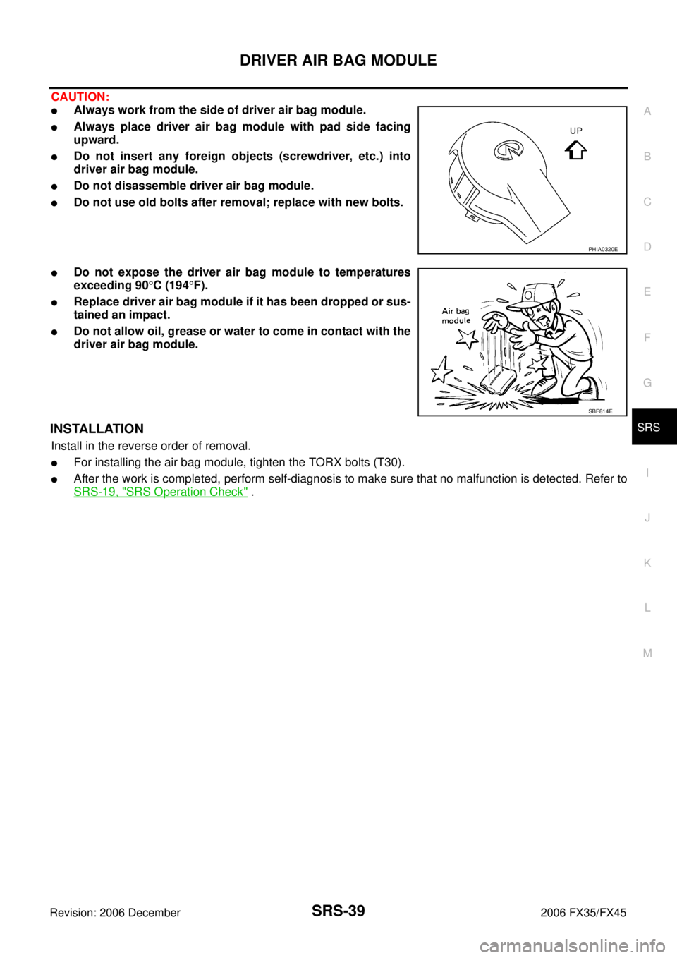
CAUTION:
�Always work from the side of driver air bag module.
�Always place driver air bag module with pad side facing
upward.
�Do not insert any foreign objects (screwdriver, etc.) into
driver air bag module.
�Do not disassemble driver air bag module.
�Do not use old bolts after removal; replace with new bolts.
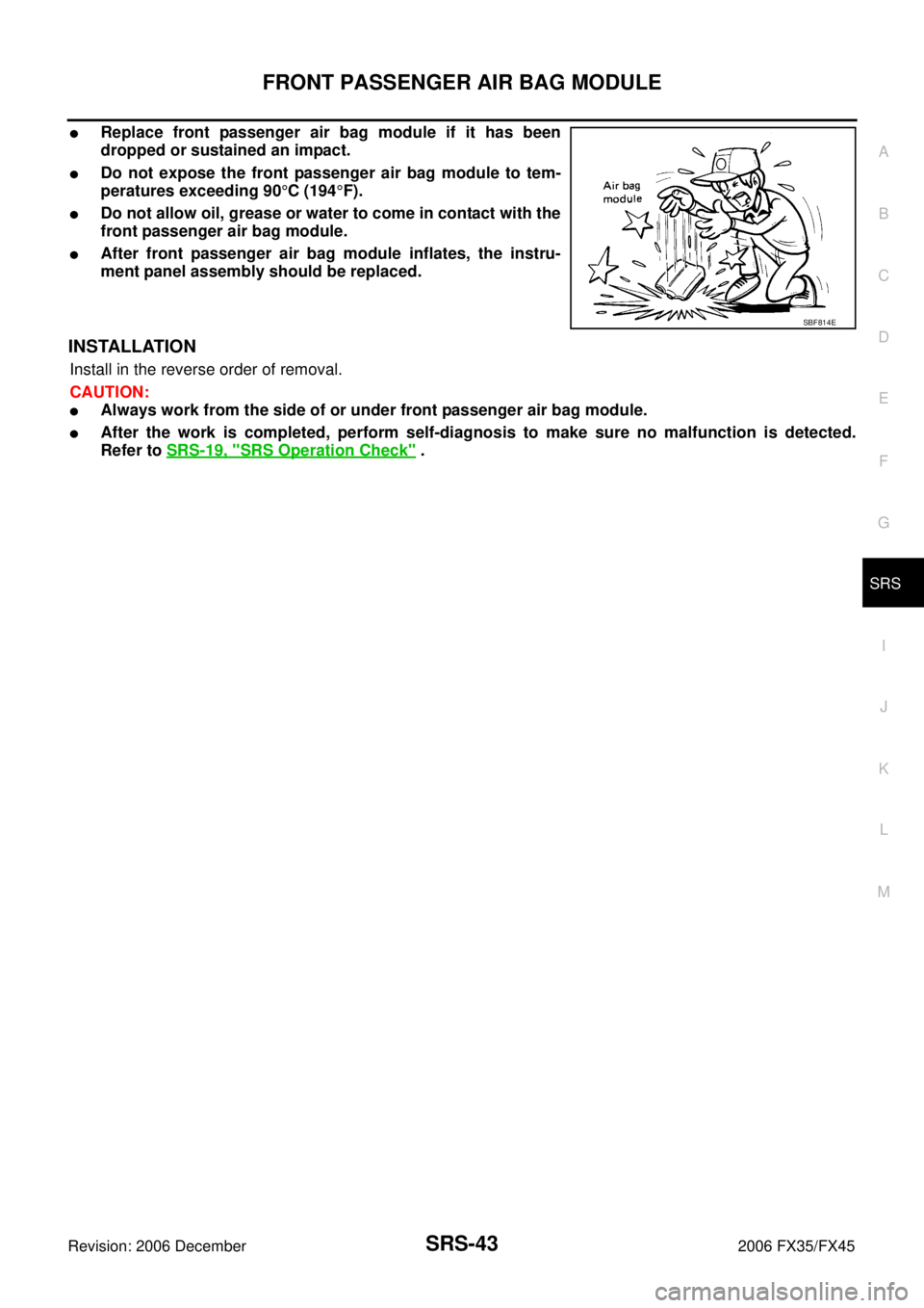
�Do not expose the driver air bag module to temperatures
exceeding 90 °C (194 °F).
�Replace driver air bag module if it has been dropped or sus-
tained an impact.
�Do not allow oil, grease or water to come in contact with the
driver air bag module.
INSTALLATION
Install in the reverse order of removal.
�For installing the air bag module, tighten the TORX bolts (T30).
�After the work is completed, perform self-diagnosis to make sure that no malfunction is detected. Refer to
SRS-19, "
SRS Operation Check" .
PHIA0320E
SBF814E
Page 4291 of 4462
FRONT PASSENGER AIR BAG MODULE SRS-43
C
D E
F
G
I
J
K L
M A
B
SRS
Revision: 2006 December 2006 FX35/FX45
�Replace front passenger air bag module if it has been
dropped or sustained an impact.
�Do not expose the front passenger air bag module to tem-
peratures exceeding 90 °C (194 °F).
�Do not allow oil, grease or water to come in contact with the
front passenger air bag module.
�After front passenger air bag module inflates, the instru-
ment panel assembly should be replaced.
INSTALLATION
Install in the reverse order of removal.
CAUTION:
�Always work from the side of or under front passenger air bag module.
�After the work is completed, perform self-diagnosis to make sure no malfunction is detected.
Refer to SRS-19, "
SRS Operation Check" .
SBF814E
Page 4342 of 4462
TF-40
FRONT OIL SEAL
Revision: 2006 December 2006 FX35/FX45
FRONT OIL SEALPFP:38189
Removal and InstallationNDS000AK
REMOVAL
1. Remove the drain plug to drain the transfer fluid. Refer to TF-9, "Replacement" .
2. Remove the front propeller shaft. Refer to PR-4, "
FRONT PROPELLER SHAFT" .
3. Remove front oil seal using a flat-bladed screwdriver. CAUTION:
Be careful not to damage the front case and front drive
shaft.
INSTALLATION
1. Apply ATF to front oil seal, install it with a drift until the end face of front case.
CAUTION:
�Do not reuse front oil seal.
�When installing, do not incline front oil seal.
2. Install front propeller shaft. Refer to PR-4, "
FRONT PROPEL-
LER SHAFT" .
3. Install transfer fluid, check fluid level and for fluid leakage. Refer to TF-9, "
Inspection" .
SDIA1782E
Tool number : ST27862000 ( — )
SDIA1783E
Page 4344 of 4462
TF-42
REAR OIL SEAL
Revision: 2006 December 2006 FX35/FX45
INSTALLATION
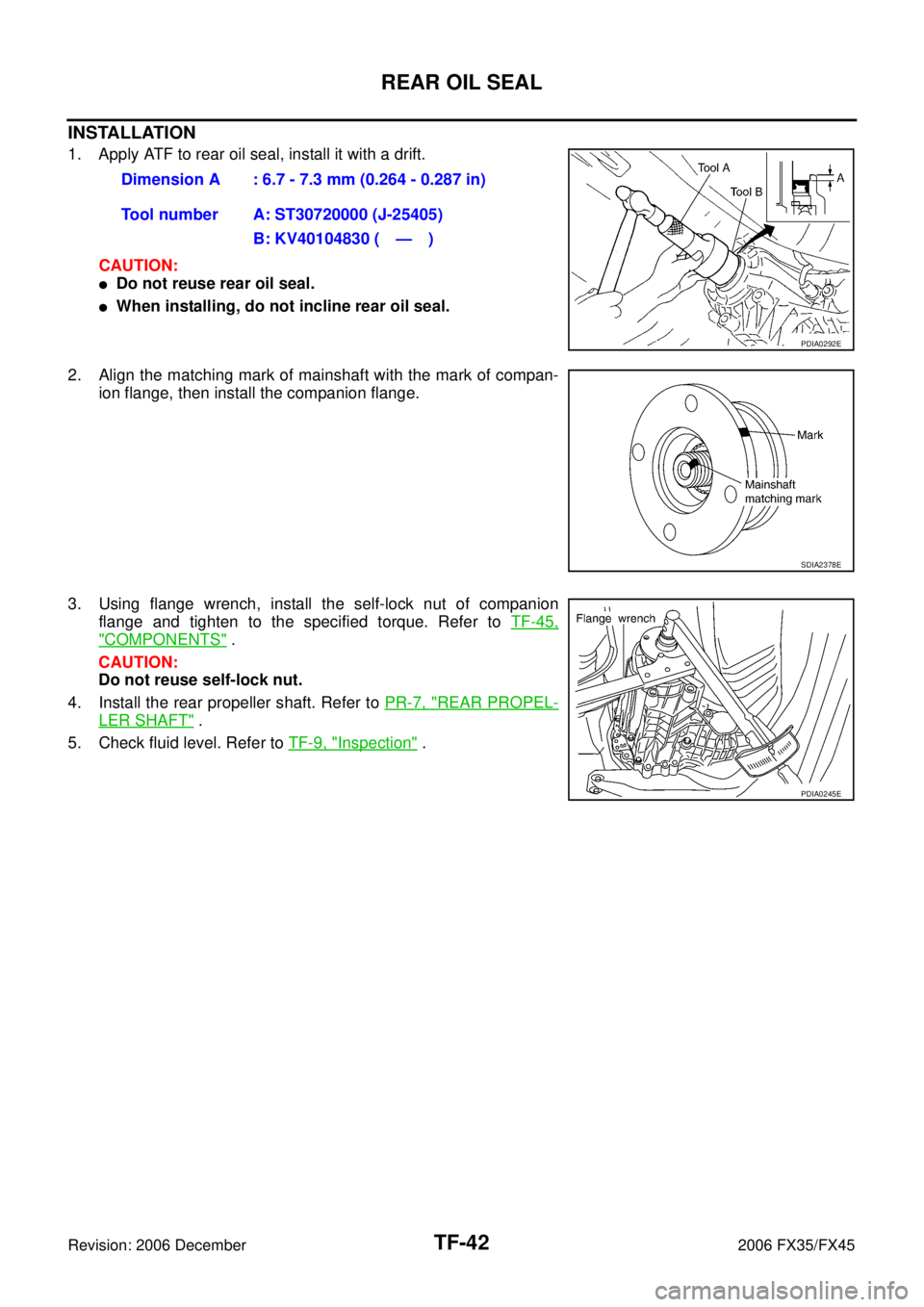
1. Apply ATF to rear oil seal, install it with a drift. CAUTION:
�Do not reuse rear oil seal.
�When installing, do not incline rear oil seal.
2. Align the matching mark of mainshaft with the mark of compan- ion flange, then install the companion flange.
3. Using flange wrench, install the self-lock nut of companion flange and tighten to the specified torque. Refer to TF-45,
"COMPONENTS" .
CAUTION:
Do not reuse self-lock nut.
4. Install the rear propeller shaft. Refer to PR-7, "
REAR PROPEL-
LER SHAFT" .
5. Check fluid level. Refer to TF-9, "
Inspection" .
Dimension A : 6.7 - 7.3 mm (0.264 - 0.287 in)
Tool number A: ST30720000 (J-25405) B: KV40104830 ( — )
PDIA0292E
SDIA2378E
PDIA0245E

8. Disconnect oil pressure")