Page 1238 of 4462
![INFINITI FX35 2006 Service Manual CO-44
[VK45DE]
RADIATOR
Revision: 2006 December 2006 FX35/FX45
CAUTION:
When installing a radiator cap, thoroughly wipe out the radiator filler neck to remove any waxy residue
or foreign material.
Ch](/manual-img/42/57019/w960_57019-1237.png "INFINITI FX35 2006 Service Manual CO-44
[VK45DE]
RADIATOR
Revision: 2006 December 2006 FX35/FX45
CAUTION:
When installing a radiator cap, thoroughly wipe out the radiator filler neck to remove any waxy residue
or foreign material.
Ch")
CO-44
[VK45DE]
RADIATOR
Revision: 2006 December 2006 FX35/FX45
CAUTION:
When installing a radiator cap, thoroughly wipe out the radiator filler neck to remove any waxy residue
or foreign material.
Checking RadiatorNBS003KM
Check radiator for mud or clogging. If necessary, clean radiator as follows:
CAUTION:
�Be careful not to bend or damage the radiator fins.
�When radiator is cleaned without removal, remove all surrounding parts such as cooling fan, radi-
ator shroud and horns. Then tape the harness and electrical connectors to prevent water from
entering.
1. Apply water by hose to the back side of the radiator core vertically downward.
2. Apply water again to all radiator core surface once per minute.
3. Stop washing if any stains no longer flow out from radiator.
4. Blow air into the back side of radiator core vertically downward.
�Use compressed air lower than 490 kPa (5 kg/cm2 , 71 psi) and keep distance more than 30 cm (11.8
in).
5. Blow air again into all the radiator core surfaces once per minute until no water sprays out.
Page 1239 of 4462
RADIATOR (ALUMINUM TYPE) CO-45
[VK45DE]
C
D E
F
G H
I
J
K L
M A
CO
Revision: 2006 December 2006 FX35/FX45
RADIATOR (ALUMINUM TYPE)PFP:21460
ComponentsNBS005RX
Disassembly and AssemblyNBS003KN
PREPARATION
1. Attach spacer to tip of radiator plate pliers A (SST). Spacer specification: 18 mm (0.71 in) wide × 8.5 mm (0.335 in)
long × 1.5 mm (0.059 in) thick.
2. Make sure that when radiator plate pliers A are closed dimension H ′′ is approx. 7.6 mm (0.299 in).
3. Adjust dimension H ′′ with spacer, if necessary.
DISASSEMBLY
1. Remove upper and lower tanks with radiator plate pliers B
(SST).
CAUTION:
Do not disassemble lower tank and A/T fluid cooler.
NOTE:
Regard lower tank and A/T fluid cooler as an assembly.
1. Upper tank 2. Sealing rubber 3. Core
4. Lower tank (with A/T fluid cooler)
PBIC2549E
SLC655CB
SLC903-A
Page 1242 of 4462
![INFINITI FX35 2006 Service Manual CO-48
[VK45DE]
RADIATOR (ALUMINUM TYPE)
Revision: 2006 December 2006 FX35/FX45
4. Make sure that the rim is completely crimped down.
5. Make sure that there is no leakage. Refer to CO-48, "
INSPECT](/manual-img/42/57019/w960_57019-1241.png "INFINITI FX35 2006 Service Manual CO-48
[VK45DE]
RADIATOR (ALUMINUM TYPE)
Revision: 2006 December 2006 FX35/FX45
4. Make sure that the rim is completely crimped down.
5. Make sure that there is no leakage. Refer to CO-48, \"
INSPECT")
CO-48
[VK45DE]
RADIATOR (ALUMINUM TYPE)
Revision: 2006 December 2006 FX35/FX45
4. Make sure that the rim is completely crimped down.
5. Make sure that there is no leakage. Refer to CO-48, "
INSPECTION" .
INSPECTION
1. Apply pressure with radiator cap tester adapter (SST) and radia-
tor cap tester (commercial service tool).
�provide used radiator and connect it to tested radiator using
radiator hoses as shown in the figure.
NOTE:
The used radiator should be tested beforehand to confirm it
has no leakage. If used one is not available, it is possible to
use new service part as a radiator testing tool.
WARNING:
To prevent the risk of hose coming undone while under pressure, securely fasten it down with
hose clamp.
CAUTION:
Attach hose to A/T fluid cooler to seal its inlet and outlet.
2. Check for leakage by soaking radiator in water container with the testing pressure applied. Standard height “H” : 8.0 - 8.4 mm (0.315 - 0.331 in)
SLC554A
Testing pressure
: 157 kPa (1.6 kg/cm
2 , 23 psi)PBIC1658E
PBIC1699E
Page 1243 of 4462
![INFINITI FX35 2006 Service Manual COOLING FAN CO-49
[VK45DE]
C
D E
F
G H
I
J
K L
M A
CO
Revision: 2006 December 2006 FX35/FX45
COOLING FANPFP:21140
Components (Crankshaft Driven type)NBS005RY
Removal and InstallationNBS003](/manual-img/42/57019/w960_57019-1242.png "INFINITI FX35 2006 Service Manual COOLING FAN CO-49
[VK45DE]
C
D E
F
G H
I
J
K L
M A
CO
Revision: 2006 December 2006 FX35/FX45
COOLING FANPFP:21140
Components (Crankshaft Driven type)NBS005RY
Removal and InstallationNBS003")
COOLING FAN CO-49
[VK45DE]
C
D E
F
G H
I
J
K L
M A
CO
Revision: 2006 December 2006 FX35/FX45
COOLING FANPFP:21140
Components (Crankshaft Driven type)NBS005RY
Removal and InstallationNBS003KO
REMOVAL
1. Remove air duct (inlet). Refer to EM-177, "AIR CLEANER AND AIR DUCT" .
2. Remove engine front undercover with power tool.
3. Remove radiator shroud (lower). Refer to CO-41, "
RADIATOR" .
4. Remove drive belts. Refer to EM-174, "
DRIVE BELTS" .
5. Remove fan coupling and cooling fan assembly. CAUTION:
Do not damage or scratch radiator core when removing.
6. Remove cooling fan from fan coupling.
INSPECTION AFTER REMOVAL
Fan Coupling
Inspect fan coupling for oil leakage and bimetal conditions.
�If anything is found, replace fan coupling.
Cooling Fan
Inspect cooling fan for crack or unusual bend.
�If anything is found, replace cooling fan.
INSTALLATION
Note the following, install in the reverse order of removal.
�Install cooling fan with its front mark “F” facing front of vehicle. Refer to CO-49, "Removal and Installation"
.
1. Cooling fan 2. Fan coupling 3. Fan pulley
4. Water pump
PBIC1537E
SLC072
Page 1244 of 4462
CO-50
[VK45DE]
COOLING FAN
Revision: 2006 December 2006 FX35/FX45
Components (Motor Driven Type)NBS005RZ
Removal and InstallationNBS003KP
REMOVAL
1. Remove front grille. Refer to EI-22, "FRONT GRILLE" .
2. Disconnect harness connector from fan motor.
3. Remove cooling fan assembly. CAUTION:
Do not damage or scratch A/C condenser when removed.
INSTALLATION
Install in the reverse order of removal.
�Cooling fan is controlled by ECM. For details. Refer to EC-1171, "DTC P1217 ENGINE OVER TEMPER-
ATURE" .
Disassembly and Assembly (Motor Driven Type)NBS003KQ
DISASSEMBLY
1. Remove cooling fan from fan motor.
2. Remove fan motor from fan grille.
INSPECTION AFTER DISASSEMBLY
Cooling Fan
Inspect cooling fan for crack or unusual bend.
�If anything is found, replace cooling fan.
ASSEMBLY
Assemble in the reverse order of disassembly.
1. Cooling fan 2. Fan grille 3. Fan motor
PBIC1666E
Page 1245 of 4462
![INFINITI FX35 2006 Service Manual WATER PUMP CO-51
[VK45DE]
C
D E
F
G H
I
J
K L
M A
CO
Revision: 2006 December 2006 FX35/FX45
WAT E R P U MPPFP:21020
ComponentsNBS005S0
Removal and InstallationNBS003KR
CAUTION:
�When remo](/manual-img/42/57019/w960_57019-1244.png "INFINITI FX35 2006 Service Manual WATER PUMP CO-51
[VK45DE]
C
D E
F
G H
I
J
K L
M A
CO
Revision: 2006 December 2006 FX35/FX45
WAT E R P U MPPFP:21020
ComponentsNBS005S0
Removal and InstallationNBS003KR
CAUTION:
�When remo")
WATER PUMP CO-51
[VK45DE]
C
D E
F
G H
I
J
K L
M A
CO
Revision: 2006 December 2006 FX35/FX45
WAT E R P U MPPFP:21020
ComponentsNBS005S0
Removal and InstallationNBS003KR
CAUTION:
�When removing water pump, be careful not to get engine coolant on drive belts.
�Water pump can not be disassembled and should be replaced as a unit.
�After installing water pump, connect hose and clamp securely, then check for leaks using radiator
cap tester (commercial service tool) and radiator cap tester adapter [SST: EG17650301 (J33984-
A)].
REMOVAL
1. Drain engine coolant from drain plugs on radiator and both side of cylinder block. Refer to CO-38, "Chang-
ing Engine Coolant" and EM-249, "DISASSEMBLY" .
CAUTION:
�Perform this step when engine is cold.
�Do not spill engine coolant on drive belts.
2. Remove following parts:
�Engine front undercover
�Air duct (inlet); Refer to EM-177, "AIR CLEANER AND AIR DUCT" .
�Alternator, water pump and A/C compressor belt; Refer to EM-174, "DRIVE BELTS" .
3. Remove fan coupling with cooling fan, and then water pump pulley.
4. Remove water pump.
�Engine coolant will leak from cylinder block, so have a receptacle ready under vehicle.
CAUTION:
�Handle the water pump vane so that it does not contact any other parts.
�Do not disassemble water pump.
1. Water pump pulley 2. Water pump 3. Gasket
PBIC1538E
Page 1246 of 4462
CO-52
[VK45DE]
WATER PUMP
Revision: 2006 December 2006 FX35/FX45
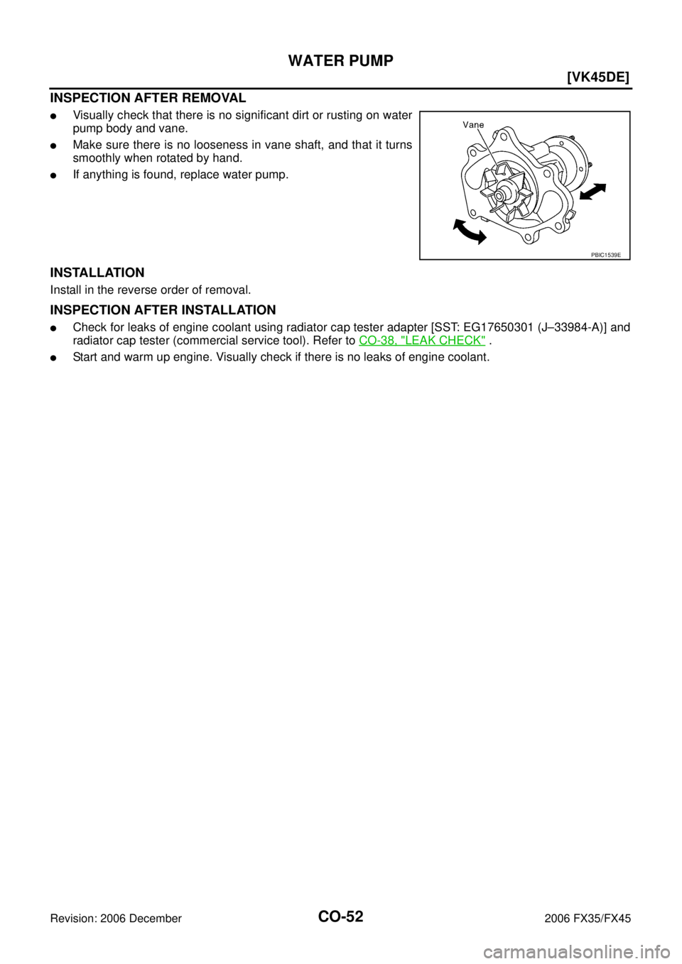
INSPECTION AFTER REMOVAL
�Visually check that there is no significant dirt or rusting on water
pump body and vane.
�Make sure there is no looseness in vane shaft, and that it turns
smoothly when rotated by hand.
�If anything is found, replace water pump.
INSTALLATION
Install in the reverse order of removal.
INSPECTION AFTER INSTALLATION
�Check for leaks of engine coolant using radiator cap tester adapter [SST: EG17650301 (J–33984-A)] and
radiator cap tester (commercial service tool). Refer to CO-38, "
LEAK CHECK" .
�Start and warm up engine. Visually check if there is no leaks of engine coolant.
PBIC1539E
Page 1247 of 4462
THERMOSTAT AND WATER CONTROL VALVE CO-53
[VK45DE]
C
D E
F
G H
I
J
K L
M A
CO
Revision: 2006 December 2006 FX35/FX45
THERMOSTAT AND WATER CONTROL VALVEPFP:21200
ComponentsNBS005S1
1. O-ring 2. Water outlet pipe 3. Thermostat housing
4. Radiator cap 5. Radiator hose (upper) 6. Water hose
7. Water hose 8. Water pipe 9. Water hose
10. Water hose 11. Thermostat 12. Rubber ring
13. Water inlet 14. Water suction hose 15. Water suction pipe
16. Radiator hose (lower) 17. Water hose 18. Water hose
19. O-ring 20. Heater pipe 21. Heater hose
22. Gasket 23. Water outlet 24. Water control valve
25. Rubber ring 26. O-ring 27. Water connector
28. Heater hose 29. Gasket
A. To radiator B. To oil cooler C. To cylinder block
PBIC4557E
![INFINITI FX35 2006 Service Manual RADIATOR (ALUMINUM TYPE) CO-45
[VK45DE]
C
D E
F
G H
I
J
K L
M A
CO
Revision: 2006 December 2006 FX35/FX45
RADIATOR (ALUMINUM TYPE)PFP:21460
ComponentsNBS005RX
Disassembly and AssemblyNBS00](/manual-img/42/57019/w960_57019-1238.png "INFINITI FX35 2006 Service Manual RADIATOR (ALUMINUM TYPE) CO-45
[VK45DE]
C
D E
F
G H
I
J
K L
M A
CO
Revision: 2006 December 2006 FX35/FX45
RADIATOR (ALUMINUM TYPE)PFP:21460
ComponentsNBS005RX
Disassembly and AssemblyNBS00")
![INFINITI FX35 2006 Service Manual CO-50
[VK45DE]
COOLING FAN
Revision: 2006 December 2006 FX35/FX45
Components (Motor Driven Type)NBS005RZ
Removal and InstallationNBS003KP
REMOVAL
1. Remove front grille. Refer to EI-22, "FRONT GRILLE](/manual-img/42/57019/w960_57019-1243.png "INFINITI FX35 2006 Service Manual CO-50
[VK45DE]
COOLING FAN
Revision: 2006 December 2006 FX35/FX45
Components (Motor Driven Type)NBS005RZ
Removal and InstallationNBS003KP
REMOVAL
1. Remove front grille. Refer to EI-22, \"FRONT GRILLE")
![INFINITI FX35 2006 Service Manual THERMOSTAT AND WATER CONTROL VALVE CO-53
[VK45DE]
C
D E
F
G H
I
J
K L
M A
CO
Revision: 2006 December 2006 FX35/FX45
THERMOSTAT AND WATER CONTROL VALVEPFP:21200
ComponentsNBS005S1
1. O-ring](/manual-img/42/57019/w960_57019-1246.png "INFINITI FX35 2006 Service Manual THERMOSTAT AND WATER CONTROL VALVE CO-53
[VK45DE]
C
D E
F
G H
I
J
K L
M A
CO
Revision: 2006 December 2006 FX35/FX45
THERMOSTAT AND WATER CONTROL VALVEPFP:21200
ComponentsNBS005S1
1. O-ring")