2006 GREAT WALL HOVER ad blue
[x] Cancel search: ad bluePage 19 of 425

Electrical system
The structure and parameter of the electrical system are shown in table 7.
Table 7 Structure And Parameter of Electrical System
No. Item Structure and Parameter
1 Power, starting and charging system
1.1 Lines Singe line system, voltage DC 12V, negative earth
1.2 Accumulator 55D26R maintenance free type, voltage 12V, 20 hours capacity 60Ah, storage
capacity 101min, low temperature starting current 475A
1.3 Starter 12V, 1.2kW
1.4 generator Internally furnished with adjustor type generator. 14V, 90A
2 Illumination and signal s ystem
2.1 Front illumination light
white, major high beam 60W,1 on the left and right respectively,
auxiliary high
beam 55W,1 on the left and right respectively, passing
lamp 55W,1 on the left and right respectively. Head light base center
height H: 920mm±20mm
2.2 Position light Front position lamp: white, 5W,1 on the left and right respectively.
Rear parking lights: red, 5W,1 on the left and right respectively.
2.3 turn light Amber。Front and rear turn light: 21W,1 on the left and right
respectively. Side turn light: 5W,1 on the left and right respectively,
2.4 Fog light Front fog light: white, 55W, 1 on the left and right respectively. Rear
fog light: red, LED,1 on the left and right respectively.
2.5 Brake light Red, 21W, 1 on the left and right respectively, high position brake light,
10W, 2 in the middle
2.6 License light White, 5W, 1 on the left and right respectively.
2.7 Backup light White, 21W, 1 on the left and right respectively.
2.8 Danger warning signal light All the turning signal lights, danger alarm switch control
2.9 Back repeating reflector Red, none triangle shape, forming combination light with the rear fog
light
2.10 Front, middle and back ceiling light
in the room White. Front indoor ceiling light: 10W, 2 pieces. Middle indoor ceiling
light: 10W, 1 piece. Back indoor ceiling lights: 5W, 1 piece
2.11 Cigar lighter illumination Blue, 3W, 1 piece
2.12 Ash tray illumination White, 3W, 1 piece
3 Meter system
3.1 Combined instrument Car speed odometer, engine speed indicator , water t emperature met er,
fuel gage
3.2 Indicator lamp Refer to the drawing
4 Auxiliary electrical system
4.1 Rain wiper system Front and rear rain wiper DC motor. Front rain wiper: four rods type,
electric drive three gears (high and low speed + adjustable interval),
scraper 2 pieces, 55W. Rear rain wiper: single arm type, electric drive
one gear, with 1 scraper plate, 21W
4.2 Defogging, defrosting device Front wind window hearing type, back wind window heating type
glass, switch control
4.3 Electric drive glass frame riser Drive side general control, independent control oh other windows and
doors
4.4 Central control lock With r emote control
4.5 Camborne power socket 12V, 2 pieces
4.6 Radio, CD and loudspeaker Stereo radio, six discs CD, four sound channels
Page 76 of 425

Transmission-37
jRemove the gear hub
k
Remove the spacing plate
l. Use the circlip pliers to remove the circlip.
Caution: It should select the circlip for shaft according the angle
when install it.
m.Remove the high and low geared sleeve and gear hub
n. Remove the low-speed driven gear, needle bearing and rear output
shaft
Caution: When install the low-speed driven gear, it should use the
plug gage to measure the axial clearance of low-speed driven gear
axial clearance to ensure the axial clearance is 0.17-0.284 mm
Mark
Thickness (mm)
White
Blue
Green
Page 85 of 425

Automatic transmission-9
Table 3.1 Feature parameter of temperature /resistance
-2013,638
5,177
2,278
177
7517,287
6,616
2,723
196
85
Figure 3.2 Pin number of temperature /resistance
Pin No. Wire color Connected solenoid valve
1 Red solenoid valve 1
2 Blue solenoid valve 2
3 yellow solenoid valve 3
4 orange solenoid valve 4
5 green solenoid valve 5
6 violet solenoid valve 6
7 brown solenoid valve 7
8 green solenoid valve 5
9 white temperature sensor
10 white temperature sensor
ohm
Temperature
Centigrade degree
Page 86 of 425

Automatic transmission-10
Figure 3.3 Schematic diagram of temperature sensor position and solenoid valve wiring
2.Throttle position sensor
Figure 3.4 gear sensor
solenoid valve 4 (orange )
ground wire (2)
solenoid valve 7 power supply connectorolenoid valve 6 (violet ) ground wiretemperature sensor solenoid valve (red ) ground wire
solenoid
valve (green )
solenoid valve (yellow )
solenoid valve (blue ) ground wire
ground wire
ground wire
Page 131 of 425

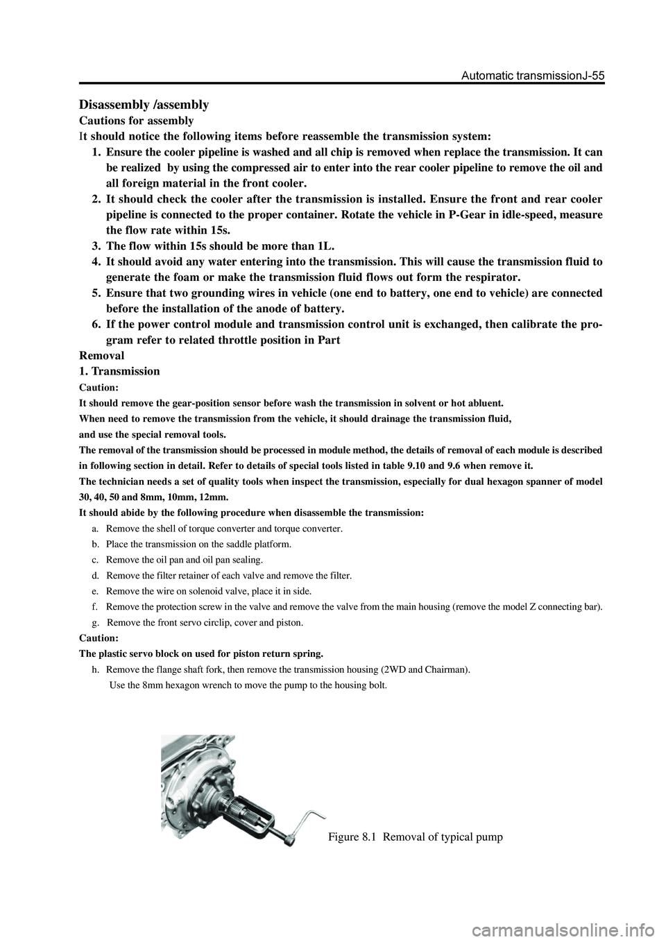
Figure 8.1 Removal of typical pump
Disassembly /assembly
Cautions for assembly
It should notice the following items before reassemble the transmission system:
1. Ensure the cooler pipeline is washed and all chip is removed when replace the transmission. It can
be realized by using the compressed air to enter into the rear cooler pipeline to remove the oil and
all foreign material in the front cooler.
2. It should check the cooler after the transmission is installed. Ensure the front and rear cooler
pipeline is connected to the proper container. Rotate the vehicle in P-Gear in idle-speed, measure
the flow rate within 15s.
3. The flow within 15s should be more than 1L.
4. It should avoid any water entering into the transmission. This will cause the transmission fluid to
generate the foam or make the transmission fluid flows out form the respirator.
5. Ensure that two grounding wires in vehicle (one end to battery, one end to vehicle) are connected
before the installation of the anode of battery.
6. If the power control module and transmission control unit is exchanged, then calibrate the pro-
gram refer to related throttle position in Part
Removal
1. Transmission
Caution:
It should remove the gear-position sensor before wash the transmission in solvent or hot abluent.
When need to remove the transmission from the vehicle, it should drainage the transmission fluid,
and use the special removal tools.
The removal of the transmission should be processed in module method, the details of removal of each module is described
in following section in detail. Refer to details of special tools listed in table 9.10 and 9.6 when remove it.
The technician needs a set of quality tools when inspect the transmission, especially for dual hexagon spanner of model
30, 40, 50 and 8mm, 10mm, 12mm.
It should abide by the following procedure when disassemble the transmission:
a. Remove the shell of torque converter and torque converter.
b. Place the transmission on the saddle platform.
c. Remove the oil pan and oil pan sealing.
d. Remove the filter retainer of each valve and remove the filter.
e. Remove the wire on solenoid valve, place it in side.
f. Remove the protection screw in the valve and remove the valve from the main housing (remove the model Z connecting bar).
g. Remove the front servo circlip, cover and piston.
Caution:
The plastic servo block on used for piston return spring.
h. Remove the flange shaft fork, then remove the transmission housing (2WD and Chairman).
Use the 8mm hexagon wrench to move the pump to the housing bolt.
Page 160 of 425

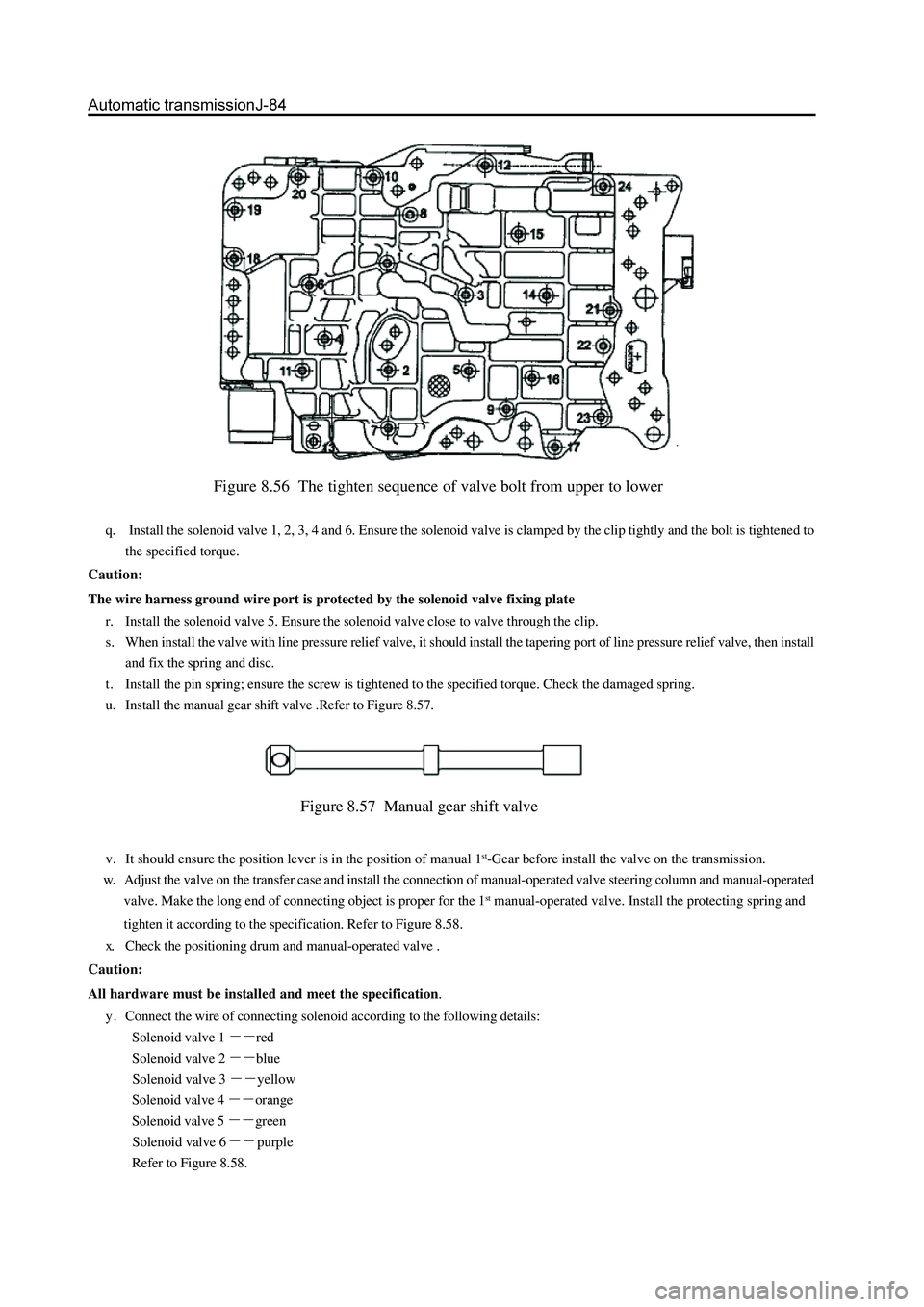
Figure 8.56 The tighten sequence of valve bolt from upper to lower
q. Install the solenoid valve 1, 2, 3, 4 and 6. Ensure the solenoid valve is clamped by the clip tightly and the bolt is tightened to
the specified torque.
Caution:
The wire harness ground wire port is protected by the solenoid valve fixing plate
r. Install the solenoid valve 5. Ensure the solenoid valve close to valve through the clip.
s. When install the valve with line pressure relief valve, it should install the tapering port of line pressure relief valve, then install
and fix the spring and disc.
t . Install the pin spring; ensure the screw is tightened to the specified torque. Check the damaged spring.
u. Install the manual gear shift valve .Refer to Figure 8.57.
Figure 8.57 Manual gear shift valve
v. It should ensure the position lever is in the position of manual 1st-Gear before install the valve on the transmission.
w. Adjust the valve on the transfer case and install the connection of manual-operated valve steering column and manual-operated
valve. Make the long end of connecting object is proper for the 1
st manual-operated valve. Install the protecting spring and
tighten it according to the specification. Refer to Figure 8.58.
x. Check the positioning drum and manual-operated valve .
Caution:
All hardware must be installed and meet the specification.
y . Connect the wire of connecting solenoid according to the following details:
Solenoid valve 1
red
Solenoid valve 2
blue
Solenoid valve 3
yellow
Solenoid valve 4
orange
Solenoid valve 5
green
Solenoid valve 6
purple
Refer to Figure 8.58.
Page 328 of 425

B-Black Br- Brown G- Green Gr- Gray L- Lake blue Lg- Light green
Or- Orange P- Pink R- Red V- Violet W- White Y- Yellow
Page 355 of 425

CD Player and Air Conditioning System-2
CD Player
Function Overview
This product is a kind of car audio system with VFD multi-information integrated display screen with such functions as PLL
electronic tuning radio, CD playing and operation & control of air conditioning system, it can receive AM, FM and FM stereo
radio broadcast programs, play CDs, electronically operate and control the air conditioning system of the car. The integrated
display screen can display the working state of the radio, CD player, air conditioning system, operating mode as well as
information concerning the equalizer, clock and the temperature inside and outside.
Wiring Instructions(see the diagram)
with the speakers: the amplifier of main unit of this system is designed with 4-channel BTL output, each speaker must
be wired individually; the phase position and place of the speaker must be connected correctly; please disconnect the
player from the power supply before connecting the speaker so as to avoid the short-circuit.
2. Connecting main unit with the integrated display screen:
Use the specially-supplied 12-pin connector cable to connect the VFD integrated display screen and main unit.
3. Connection of power supply, output and communication line of main unit:
At first, connect the communication cable of the 20-pin connector plug to the air conditioner ECU, then connect the speaker
output line to other lines, finally connect the yellow memory power supply cord (10A fuse tube) directly to the positive role of
accumulator; when all the wiring is completed, connect the red power supply cord (1A fuse tube) to the positive power supply
of the ignition lock.
4. Connecting main unit with the antenna
T ypical antenna: insert the plug of coaxial cable of car’s antenna into the antenna socket of main unit.
Automatic antenna: insert the plug of coaxial cable of car’s antenna into the antenna socket of main unit, then connect the blue
antenna control cable in the 20-pin connector to the automatic antenna control end, connect the positive pole line of power
supply of automatic antenna to the positive pole of accumulator and the negative pole line to the earth.
5. Connecting main unit with CD-change box
CD player and the CD-change box are connected with the signal cables.
Prior to the installation, please be sure to remove three protective screws on the CD-change box and have it pasted with
ant-dust paper. If the protective screws are not removed, CD can not be played normally.
Attention: Improper wiring may result in the damage to the player!
(Figure 7-1) Wiring Diagram integrated display screen 12-pin connector cable20-pin connector cable
antenna adaptor
main unit