Page 71 of 234
Common Rail 2.4L TCI 85kW (115HP) Diesel Engine
DescriptionItem
NmA
1/minB
kWC
Bore: 89.9mm / Stroke: 94.6mm
Max. Power 85kW (115HP) at 3500
1/min
2Max. Torque 310Nm at 1750 - 2000
1/min
1
FordTransit 2006.5 (April 2006–)
Date of Publication: 12/2006
3 Powertrain
7180100120140160180200220240260280300100015002000250030003500400045000102030405060708090100ABC21E75914
Page 72 of 234
Common Rail 2.4L TCI 103kW (140HP) Diesel Engine
DescriptionItem
NmA
1/minB
kWC
Bore: 89.9mm / Stroke: 94.6mm
Max. Power 103kW (140HP) at 3500
1/min
2Max. Torque 375Nm at 2000 - 2250
1/min
1
FordTransit 2006.5 (April 2006–)
Date of Publication: 12/2006
3 Powertrain
7214016018020022024026028030032034036038010001500200025003000350040004500102030405060708090100110ABC12E75915
Page 74 of 234
Bore: 89.9mm / Stroke: 91.0mm
Max. Power 107kW (145HP) at 5500
1/min
2Max. Torque 210Nm at 2500 1/min1
FordTransit 2006.5 (April 2006–)
Date of Publication: 12/2006
3 Powertrain
74
Page 75 of 234

3.2 Engine Cooling
3.2.1 Auxiliary Heater Systems
WARNINGS:
Ford coolant additives are
necessary for the complete function
of the system. Only use ford
approved or equivalent specification
component, to withstand any
detrimental effects on the materials.
Do not mount components in front
of the grille or in an area of air flow
around the engine, which could
affect the engine cooling.
CAUTIONS:
Only make connections into the
heater hose between the front cab
heater and water pump return inlet.
Do not exceed the vehicle's original
coolant volume by more than 10%
Only use the manufactures
recommended (or equivalent
specification) coolant
additives/anti-freeze. Do not mix
coolant types.
•Coolant flow to cab heater must have priority
over flow to auxiliary heater or hand wash
facility.
•Coolant tube routing must be below the base
of the degas bottle.
•Use aluminum or plastic tee junction with
swaged or beaded ends to prevent hose blow
off. Reconnect original coolant tube as shown
in view E74570 (in this section) with standard
Ford water hose clip or suitable equivalent
specification clip. Ensure interference fit
between hose and 'T' joint.
•Tube routing must be secured to the body
structure or suitable brackets avoiding
electrical components or wires, hot or moving
parts and brake or fuel system components
•Hose must be heat sleeved with appropriate
material if within 100mm of exhaust
components (for example, manifold or
exhaust gas recirculating).
•The vertical clearance between the critical
cooling components (radiator, fan shroud and
radiator brackets) and both the hood inner
and outer (assembly) panels at design position
shall not be less than 15mm.
•There shall be a minimum clearance of 7mm
between the engine assembly and flexible
components (for example, hoses or wiring
harnesses) affixed to front end sheet metal
hardware, under a maximum engine torque
roll condition.
NOTE: For further information please contact
your local National Sales Company
representative, or Local Ford Dealer. If they are
unable to help you then please contact the
Vehicle Converter Advisory service at
[email protected].
FordTransit 2006.5 (April 2006–)
Date of Publication: 12/2006
3 Powertrain
75
Page 77 of 234

3.3 Accessory Drive
When the correct belt is used, tensioning is and
remains fully automatic for the life of the belt.
CAUTIONS:
Only use the manufacturers
recommended (or equivalent
specification) components
Make sure that the ancillary pulley
diameter is less than the crankshaft
pulley diameter.
Systems requiring a unique belt
NOTE: For further information please contact
your local National Sales Company
representative, or Local Ford Dealer. If they are
unable to help you then please contact the
Vehicle Converter Advisory Service at
[email protected].
The eigenfrequency of any bracket including the
auxiliary added should be above the maximum
excitation frequency of the main excitation order
of the individual engine at engine top speed. On
4-cylinder inline engines, this is the second
engine order.
3.3.1 Front End Accessory Drive
2.4l Diesel and 2.3l Petrol
CAUTION: Do not fit an additional
front end accessory drive to a
vehicle already equipped with and
air-conditioning compressor.
When engineering and installing a new front end
accessory drive, i.e. belt drive of the crankshaft
pulley, the longitudinal alignment must be within
+/- 0.25mm and angular within +/- 0.33°.
For most front end accessory drive applications
the longer Regular Production Option air
-conditioning belt can replace the standard belt
and pulley layout.
The maximum power that is available for front
end accessory drive applications, in lieu of the
air conditioning compressor is 26Nm torque at
any engine speed up to a maximum of 6kW.
FordTransit 2006.5 (April 2006–)
Date of Publication: 12/2006
3 Powertrain
77
Page 79 of 234
Front End accessory Drive Assembly on 2.3l Petrol Engine
Pulley and Belt Layout on 2.3l Petrol Engine
DescriptionItem
Alternator1
Idler2
Coolant Pump3
Power Steering Pump4
Compressor (may be replaced by ancillary unit)5
Crankshaft Pulley6
Auto Tensioner7
3.3.2 Front End Accessory Drive
2.2l Diesel
CAUTION: Do not fit an additional
front end accessory drive to a
vehicle already equipped with and
air-conditioning compressor.
When engineering and installing a new front end
accessory drive, i.e. belt drive of the crankshaft
pulley, the longitudinal alignment must be within
+/- 0.25mm and angular within +/- 0.33°.
The maximum power that is available for front
end accessory drive applications, in lieu of the
air conditioning compressor is 26Nm torque at
any engine speed up to a maximum of 6kW.
FordTransit 2006.5 (April 2006–)
Date of Publication: 12/2006
3 Powertrain
79E742191234567
Page 103 of 234
4.4.2 Generator and Alternator
Torque Curve of Alternator
Diagram E75871 shows the torque in Nm which
is required to drive the alternator. The vertical
axis (A) shows the torque [Nm] and the horizontal
axis (B) shows the alternators revolutions per
minute [1/min].
NOTE: For equivalent engine revs per minute
(RPM), the alternators revolutions, axis (B) should
be divided by the following factors: 2.66 for diesel
(2.2L and 2.4L), 2.4 for Gasoline (2.3L).
NOTE: These alternator curves do not show
spare output capacity as this would be
dependant on original vehicle features and
options
FordTransit 2006.5 (April 2006–)
Date of Publication: 12/2006
4 Electrical
1030246810121402000400060008000100001200014000160001800020000ABE75871
Page 120 of 234

4.13.3 Customer Connection Points
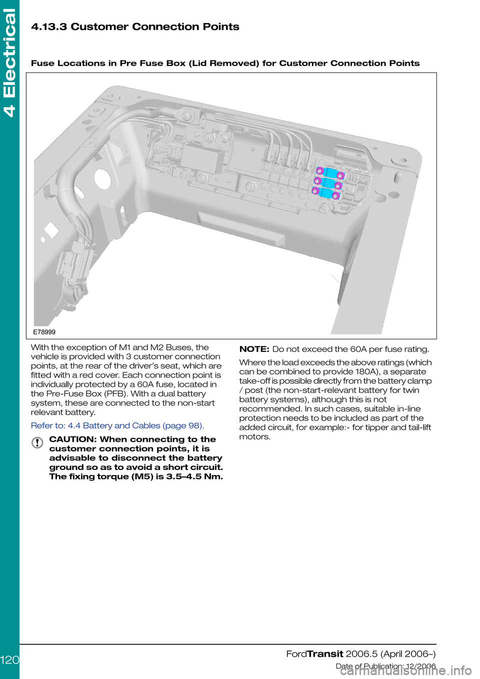
Fuse Locations in Pre Fuse Box (Lid Removed) for Customer Connection Points
With the exception of M1 and M2 Buses, the
vehicle is provided with 3 customer connection
points, at the rear of the driver’s seat, which are
fitted with a red cover. Each connection point is
individually protected by a 60A fuse, located in
the Pre-Fuse Box (PFB). With a dual battery
system, these are connected to the non-start
relevant battery.
Refer to: 4.4 Battery and Cables (page 98).
CAUTION: When connecting to the
customer connection points, it is
advisable to disconnect the battery
ground so as to avoid a short circuit.
The fixing torque (M5) is 3.5–4.5 Nm.
NOTE: Do not exceed the 60A per fuse rating.
Where the load exceeds the above ratings (which
can be combined to provide 180A), a separate
take-off is possible directly from the battery clamp
/ post (the non-start-relevant battery for twin
battery systems), although this is not
recommended. In such cases, suitable in-line
protection needs to be included as part of the
added circuit, for example:- for tipper and tail-lift
motors.
FordTransit 2006.5 (April 2006–)
Date of Publication: 12/2006
4 Electrical
120E78999